ENGINE PERFORMANCE
3.8L
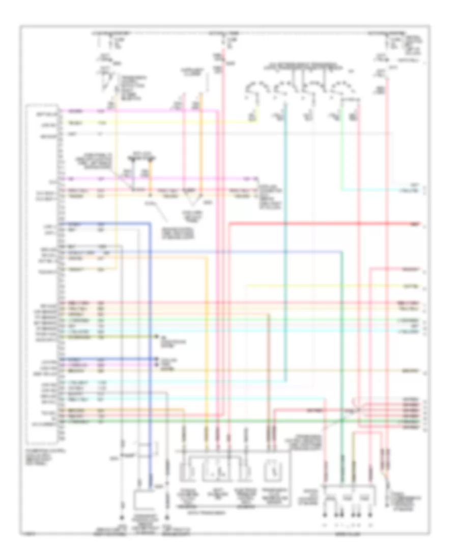
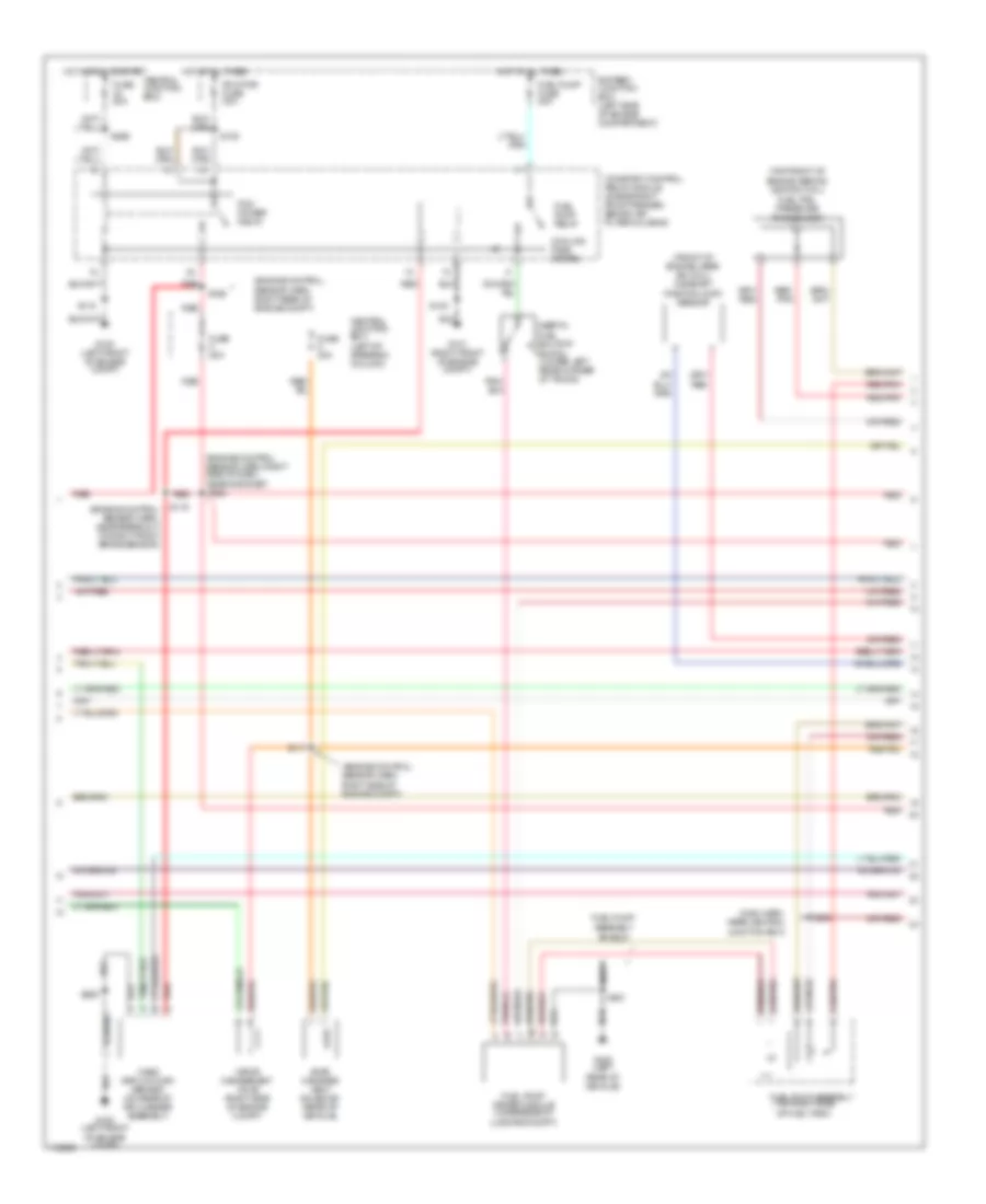
3.8L, Engine Performance Wiring Diagrams (1 of 3) for Ford Mustang 1999
 https://portal-diagnostov.com/license.html
Automotive Electricians Portal FZCO
Automotive Electricians Portal FZCO
https://portal-diagnostov.com/license.html
https://portal-diagnostov.com/license.html
Automotive Electricians Portal FZCO
Automotive Electricians Portal FZCO
List of elements for 3.8L, Engine Performance Wiring Diagrams (1 of 3) for Ford Mustang 1999:
- (dash panel to headlamp junction harn, left side of engine compt)
- (engine control harn, right side of engine compt)
- (main harn, left kick panel)
- (on left rear side of transmission) digital transmission range (dtr) sensor
- (transmission control selector harn, right rear of engine compt)
- 4r70w transmission
- Accs input
- Air conditioning system
- Air pump
- Anti-lock brakes system
- Central junction box (left of column)
- Ckp (+)
- Ckp (-)
- Cooling fans system
- Crankshaft position (ckp) sensor (center front of engine)
- Data link connector (dlc) (behind dash, right of column)
- Dlc
- Dlc (bus +)
- Dlc (bus -)
- Dtr tr1
- Dtr tr2
- Dtr tr4
- Ect sensor
- Egr vacuum
- Electronic pressure control (epc)
- Fp drv mod
- Fuse 15a
- Fuse 20a
- Fuse 5a
- G100 (left front of engine compt)
- G203 (behind dash, at right kick panel)
- Ground
- High fan
- Hot at all times
- Hot in run or start
- Iat sensor
- Ign coil
- Ignition coil (top front of engine)
- Instrument cluster
- Low fan
- Maf sensor
- Module (pcm) (behind right kick panel)
- Nca
- Powertrain control
- Radio interference capacitor (top front of engine)
- Red
- Rr ho2s
- S126
- S134
- S135
- S174
- S204
- S250
- S252
- S253
- S259
- S262
- Shft sol b
- Shift solenoids (ss)
- Sht sol a
- Solenoid
- Spark plugs
- Tcc sol
- Tcs input
- Tft sensor
- Torque converter clutch (tcc) solenoid
- Transmission control switch (tcs) (right of gear selector)
- Transmission fluid temperature sensor
- Vmv current
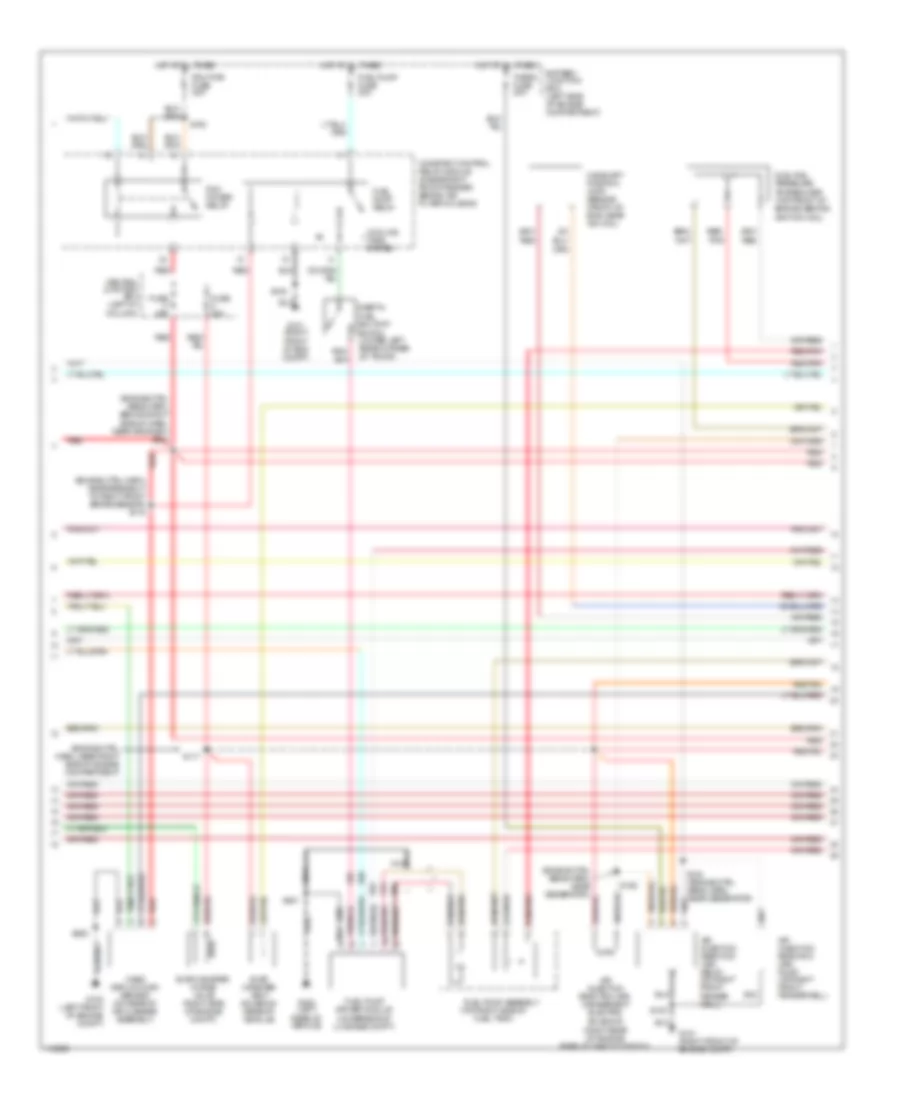
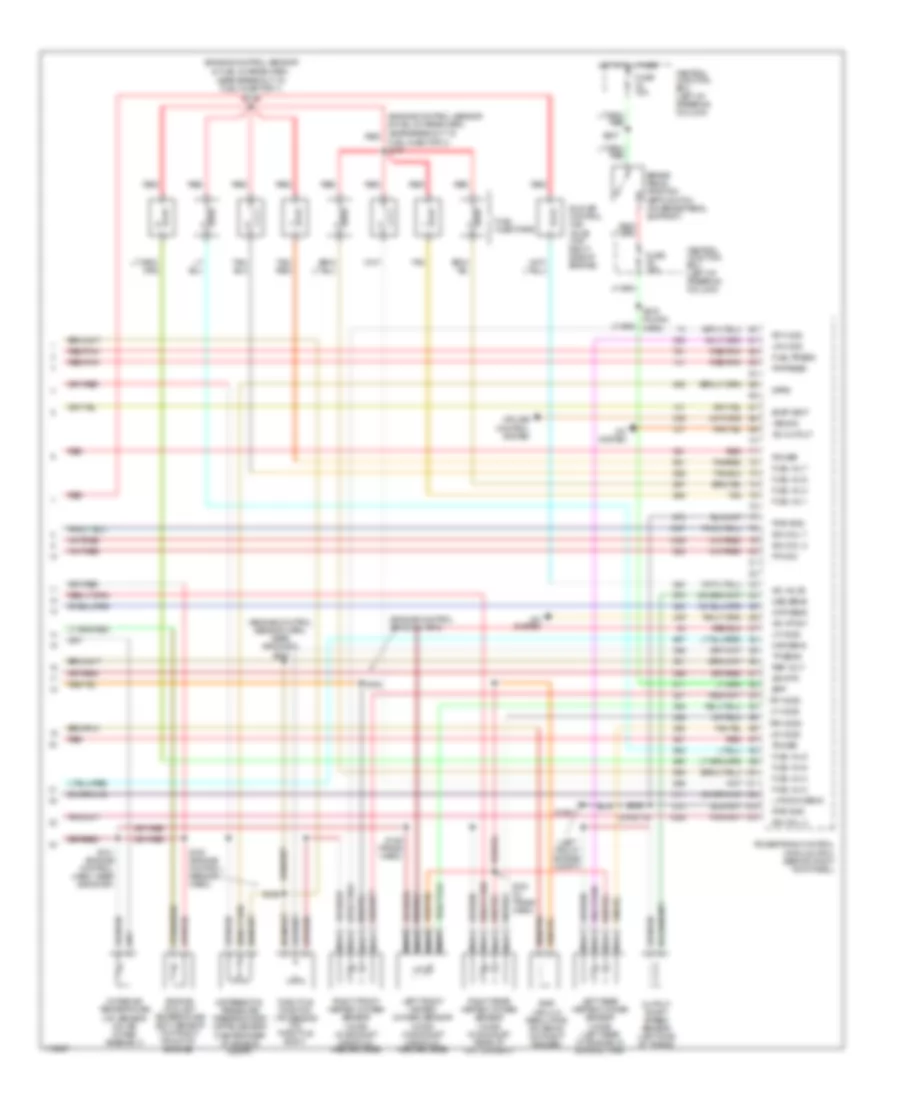
3.8L, Engine Performance Wiring Diagrams (2 of 3) for Ford Mustang 1999
 https://portal-diagnostov.com/license.html
Automotive Electricians Portal FZCO
Automotive Electricians Portal FZCO
https://portal-diagnostov.com/license.html
https://portal-diagnostov.com/license.html
Automotive Electricians Portal FZCO
Automotive Electricians Portal FZCOList of elements for 3.8L, Engine Performance Wiring Diagrams (2 of 3) for Ford Mustang 1999:
- (engine ctrl harn, near breakout to right front brake sensor) s116
- (engine ctrl harn, near right side of engine compartment)
- (engine ctrl sens harn, behind right side of dash, near grommet) s234
- (engine ctrl sens harn, near generator)
- (right rear of engine, rear of throttle body)
- (top right side of fuel tank)
- Air injection reaction (air) management electric solenoid
- Air injection reaction (air) pump (on right front fenderwell)
- Air injection reaction (air) relay (on right front fender well)
- Battery junction box (left side of engine compartment)
- Camshaft position (cmp) sensor (front of eng, near ign coil)
- Central junction box (left of column)
- Constant control relay module (inside right front fender, behind air filter housing)
- Cooling fans system
- Evap canister purge valve (right side of engine compt)
- Evap canister vent solenoid (rear of vehicle)
- Fuel pump assembly
- Fuel pump driver module (underside of luggage compt)
- Fuel pump fuse 20a
- Fuel pump relay
- Fuel rail pressure transducer (top front of engine, behind ignition coil)
- Fuse 20a
- G100 (left front of engine compt)
- G101 (right front of eng compt)
- G101 (right front of engine compt)
- G404 (left rear of vehicle)
- Hot at all times
- Inertia fuel shutoff switch (lower left rear corner of trunk)
- Mass airflow (maf) sensor (on rear of air cleaner assembly)
- Nca
- Pcm power relay
- Pcm pwr fuse 30a
- Red
- Red/ pnk
- Red/pnk
- S100
- S108
- S117
- S154 (engine ctrl sens harn, near generator)
- S155
- S250
- S451
- Therm fuse 30a
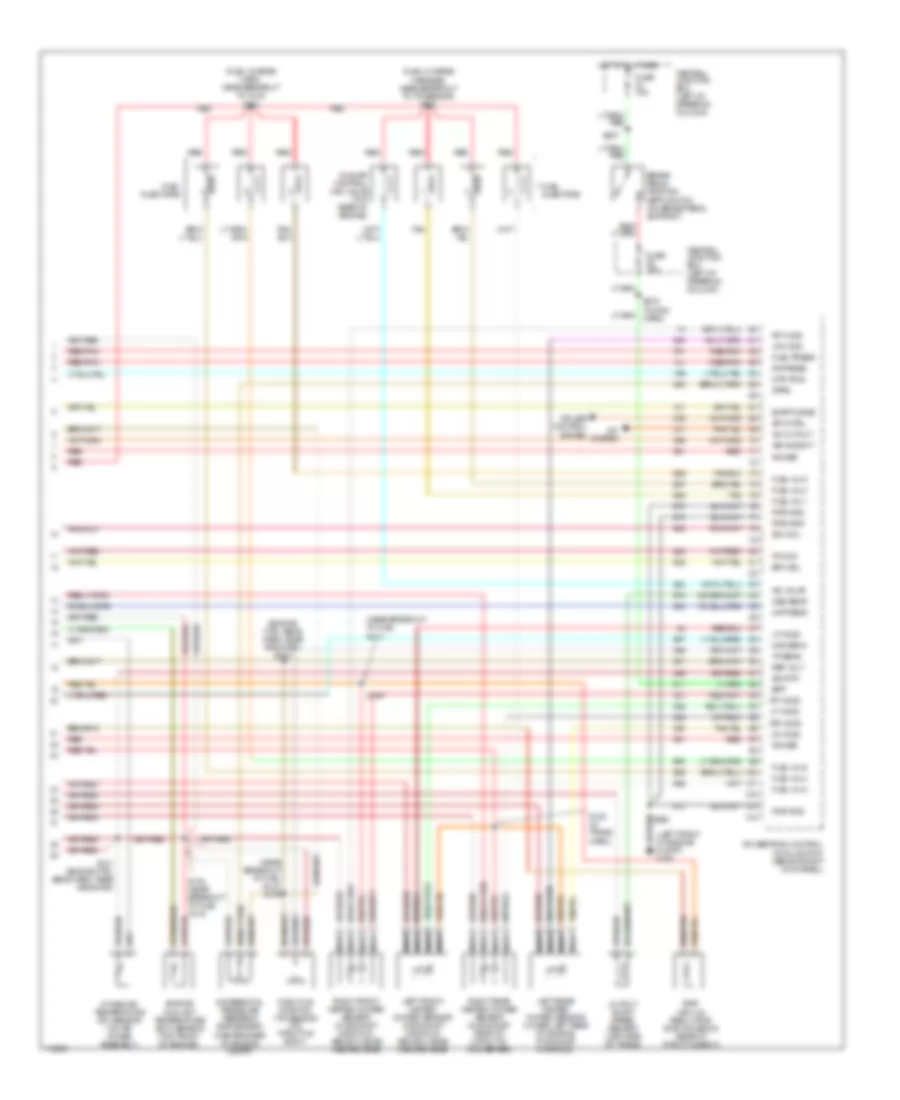
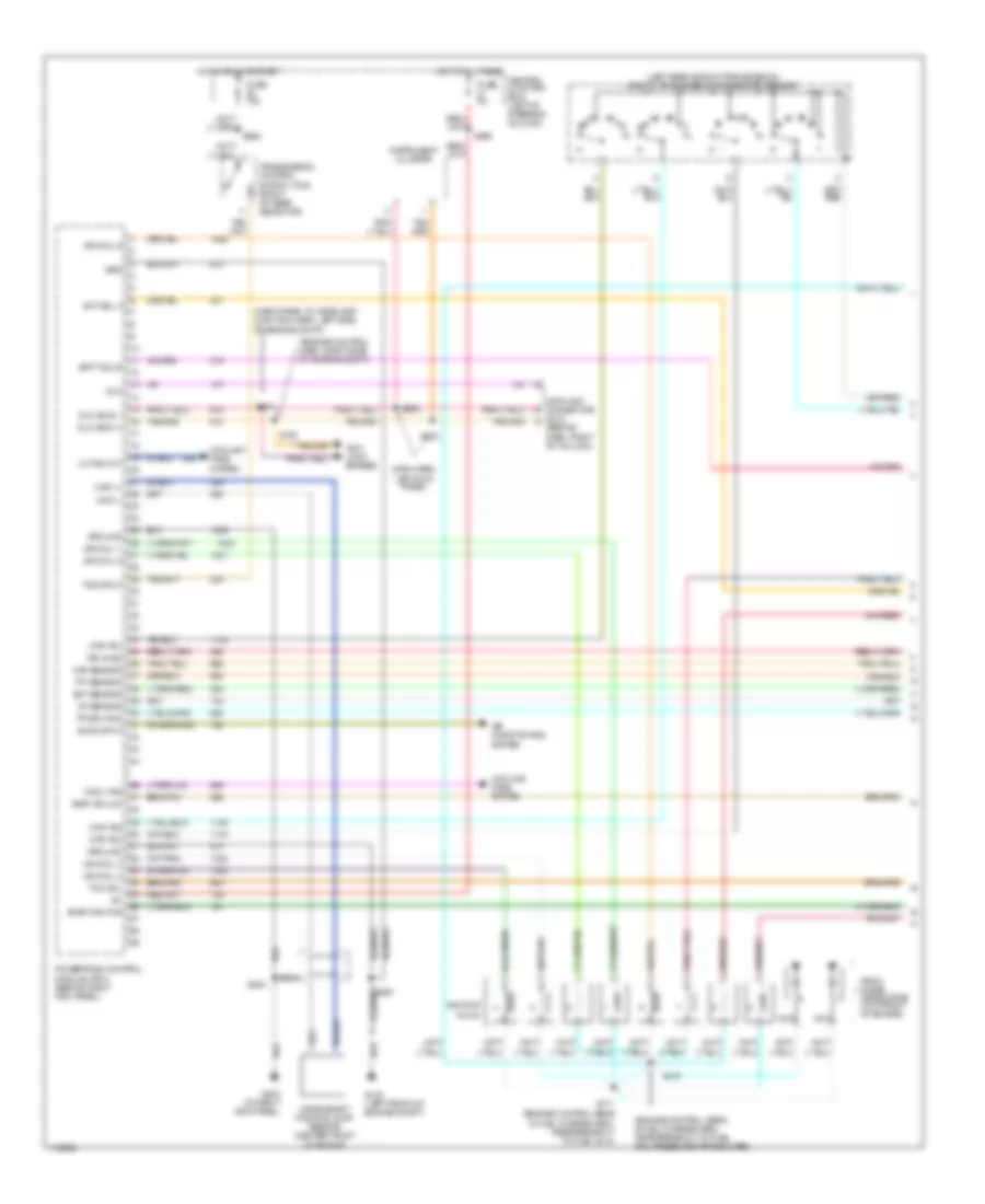
3.8L, Engine Performance Wiring Diagrams (3 of 3) for Ford Mustang 1999
 https://portal-diagnostov.com/license.html
Automotive Electricians Portal FZCO
Automotive Electricians Portal FZCO
https://portal-diagnostov.com/license.html
https://portal-diagnostov.com/license.html
Automotive Electricians Portal FZCO
Automotive Electricians Portal FZCOList of elements for 3.8L, Engine Performance Wiring Diagrams (3 of 3) for Ford Mustang 1999:
- (engine ctrl sens harn, near grommet) s200
- (fuel charge harn, near breakout to inj 6) s123
- (fuel charge harness, near breakout to tp sensor) s128
- (left front of engine compt) g100
- (near breakout to fuel inj 1)
- (near breakout to fuel inj 2) s129
- A/c cutout
- A/c system
- Air mngmnt
- Bpp
- Brake pedal position (bpp) switch (on brake pedal support)
- Central junction box (left of steering column)
- Cmp sens
- Cruise control system
- Differential pressure feedback egr sensor (center rear of engine compt)
- Dpfe
- Dtr tr3a
- Egr vacuum regulator (evr) solenoid (rear of throttle body)
- Engine coolant temperature (ect) sensor (top front of engine)
- Epc sol
- Evap purge
- Fp mon
- Fr press
- Fuel inj 1
- Fuel inj 2
- Fuel inj 3
- Fuel inj 4
- Fuel inj 5
- Fuel inj 6
- Fuel injectors
- Fuel press
- Fuse 15a
- Hot at all times
- Iac valve
- Idle air control (iac) valve (top rear of engine)
- Ign coil
- Intake air temperature (iat) sensor (on air intake assembly)
- Left front heated oxygen sensor (in exhaust manifold, above flange inboard side)
- Left rear heated oxygen sensor (lower left rear of engine, in exhaust manifold)
- Lf ho2s
- Lr ho2s
- Maf sens
- Module (pcm) (behind right kick panel)
- Nca
- Oss sens
- Output shaft speed sensor (left side of trans)
- Power
- Powertrain control
- Pwr gnd
- Red
- Red/pnk
- Ref volt
- Rf ho2s
- Right front heated oxygen sensor (in exhaust manifold, above flange inboard side)
- Right rear heated oxygen sensor (in exhaust, rear of catalytic converter)
- Rr ho2s
- S120 (in trans harn)
- S121 (engine ctrl sens harn, near grommet)
- S130 (near breakout to fuel inj 6)
- S164
- S207
- S250
- S275 (in main harn)
- Sig rtn
- Sp cntrl
- Tan
- Throttle position (tp) sensor (on throttle body)
- Tp sens
4.6L
4.6L DOHC, Engine Performance Wiring Diagrams (1 of 3) for Ford Mustang 1999
 https://portal-diagnostov.com/license.html
Automotive Electricians Portal FZCO
Automotive Electricians Portal FZCO
https://portal-diagnostov.com/license.html
https://portal-diagnostov.com/license.html
Automotive Electricians Portal FZCO
Automotive Electricians Portal FZCOList of elements for 4.6L DOHC, Engine Performance Wiring Diagrams (1 of 3) for Ford Mustang 1999:
- (behind dash, right of column)
- (dash panel to headlamp junction harn, left side of engine compt)
- (engine control harn, right side of engine compt)
- (engine control sens and fuel charge harn, near breakout to fuel rail pressure transducer)
- (main harn, left kick panel)
- (near fuel inj 1) right knock sensor
- (near fuel inj 5) left knock sensor
- Accs input
- Air conditioning
- Anti- lock brakes
- Central junction box) (left of steering column)
- Ckp (+)
- Ckp (-)
- Cool fan
- Coolant fans system
- Cooling fans system
- Crankshaft position (ckp) sensor (center front of engine)
- Data link connector (dlc)
- Dlc
- Dlc (bus +)
- Dlc (bus -)
- Ect sensor
- Egr vacuum
- Evap can pur
- Fp drv mod
- Fuse 5a
- G100 (left front of engine compt)
- G203 (right kick panel)
- Grd
- Ground
- Hot at all times
- Iat sensor
- Ign coil 1
- Ign coil 3
- Ign coil 4
- Ign coil 5
- Ign coil 6
- Ignition coils
- Instrument cluster
- L knock sens
- Lo fan out
- Maf sensor
- Module (pcm) (behind right kick panel)
- Nca
- Powertrain control
- R knock sens
- Radio noise capacitors (top front of engine)
- Red
- Rr ho2s
- S134
- S135
- S170
- S171 (engine control sens and fuel charge harn, near breakout to fuel inj 4)
- S204
- S250 or s115
- S252
- S253
- S259
- System
4.6L DOHC, Engine Performance Wiring Diagrams (2 of 3) for Ford Mustang 1999
 https://portal-diagnostov.com/license.html
Automotive Electricians Portal FZCO
Automotive Electricians Portal FZCO
https://portal-diagnostov.com/license.html
https://portal-diagnostov.com/license.html
Automotive Electricians Portal FZCO
Automotive Electricians Portal FZCOList of elements for 4.6L DOHC, Engine Performance Wiring Diagrams (2 of 3) for Ford Mustang 1999:
- (engine control sensor harn, near breakout to right front brake sensor)
- (engine control sensor harn, right rear of engine compt)
- (engine control sensor harn, right side of dash, near grommet)
- (engine control sensor harn, right side of engine compt)
- (front of engine, near ign coil) camshaft position (cmp) sensor
- (main harn, near central junction box)
- (top front of engine, behind ignition coil) fuel rail pressure transducer
- (top right side of fuel tank)
- Battery junction box (left side of engine compartment)
- Central junction box (left of steering column)
- Central junction box)
- Constant control relay module (inside right front fender, behind air filter housing)
- Cooling fans system
- Evap canister vent solenoid (rear of vehicle)
- Fuel pump assembly
- Fuel pump assembly shield
- Fuel pump driver module (underside of luggage compt)
- Fuel pump fuse 20a
- Fuel pump relay
- Fuse 20a
- G100 (left front of engine compt)
- G101 (right front of engine compt)
- G400 (left
- Hot at all times
- Hot in run or start
- Inertia fuel shutoff switch (lower left rear corner of trunk)
- Mass airflow (maf) sensor (on rear of air cleaner assembly)
- Nca
- Pcm power relay
- Pcm pwr fuse 30a
- Rear of vehicle)
- Red
- Red/ pnk
- Red/pnk
- S100
- S108
- S115
- S116
- S117
- S169
- S224
- S234
- S250
- S266
- S451
- Vapor management valve (right side of engine compt)
4.6L DOHC, Engine Performance Wiring Diagrams (3 of 3) for Ford Mustang 1999
 https://portal-diagnostov.com/license.html
Automotive Electricians Portal FZCO
Automotive Electricians Portal FZCO
https://portal-diagnostov.com/license.html
https://portal-diagnostov.com/license.html
Automotive Electricians Portal FZCO
Automotive Electricians Portal FZCOList of elements for 4.6L DOHC, Engine Performance Wiring Diagrams (3 of 3) for Ford Mustang 1999:
- (engine control sensor & fuel charge harn,
- (engine control sensor & fuel charge harn, near breakout to red
- (engine control sensor harn)
- (engine control sensor harn, near grommet)
- (left front engine compt)
- (or s115)
- A/c cutout
- A/c hp sw
- A/c system
- Bpp
- Brake pedal position (bpp) switch (on brake pedal support)
- Central junction box (left of steering column)
- Cmp sens
- Cruise control system
- Differential pressure feedback egr (dpfe) sensor (center rear of engine compt)
- Dpfe
- Egr vacuum regulator solenoid (on right fender)
- Engine coolant temperature (ect) sensor (top right front of engine)
- Evap vent
- Fp mon
- Fr press
- Fuel inj 1
- Fuel inj 2
- Fuel inj 3
- Fuel inj 4
- Fuel inj 5
- Fuel inj 6
- Fuel inj 7
- Fuel inj 8
- Fuel injector 3) s147
- Fuel injectors
- Fuel press
- Fuse 15a
- G100
- Hot at all times
- Iac valve
- Idle air control (iac) valve (top right side of engine)
- Ign coil 2
- Ign coil 7
- Ign coil 8
- Intake air temperature (iat) sensor (on air intake assembly)
- L knock sens
- Left front heated oxygen sensor (ho2s) (in exhaust manifold, inboard side)
- Left rear heated oxygen sensor (ho2s) (left rear of engine, in exhaust man)
- Lf ho2s
- Lr ho2s
- Maf sens
- Module (pcm) (behind right kick panel)
- Nca
- Near breakout to fuel injector 7)
- Oss sens
- Output shaft speed sensor (left side of trans)
- Power
- Powertrain control
- Pwr gnd
- Red
- Red/pnk
- Ref volt
- Rf ho2s
- Right front heated oxygen sensor (ho2s) (in exhaust manifold, inboard side)
- Right rear heated oxygen sensor (ho2s) (in exhaust, rear of cat convert)
- Rr ho2s
- S120 (in trans harn)
- S121 (engine control harn, near grommet)
- S126 (trans harn)
- S129
- S130 (engine control sensor harn)
- S148
- S164
- S200
- S207
- S250
- S275 (in main harn)
- Sig rtn
- Tan
- Tan/ red
- Tan/red
- Throttle position (tp) sensor (on throttle body)
- Tp sens
- Vss sig
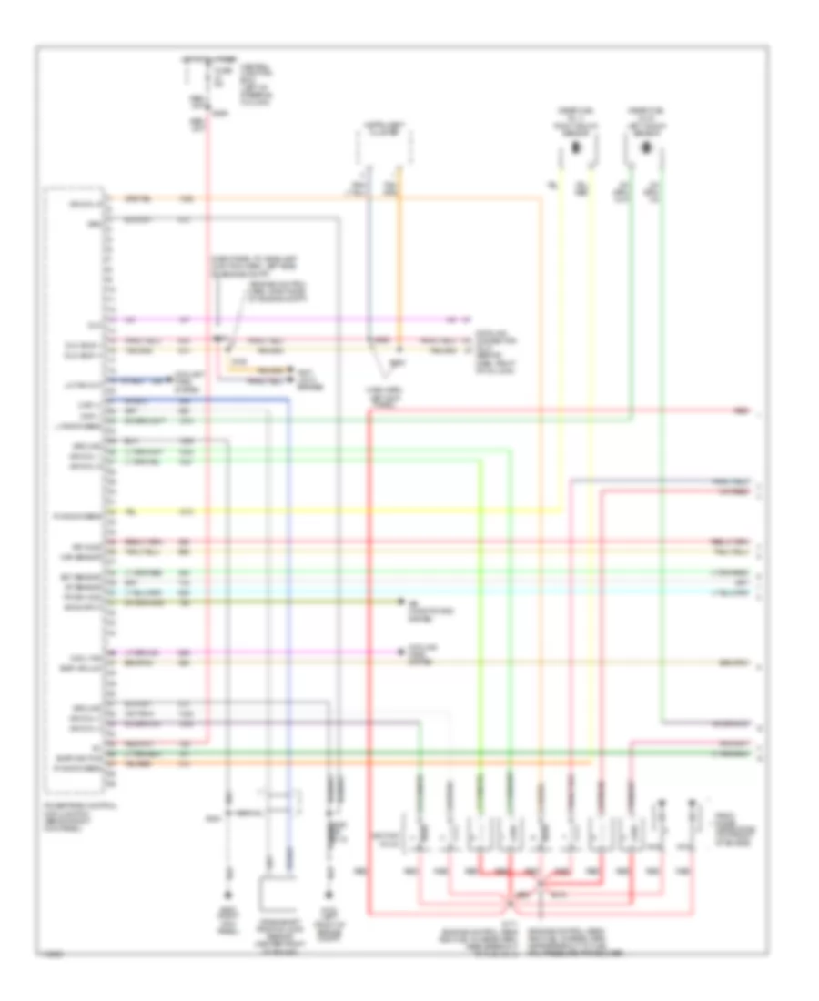
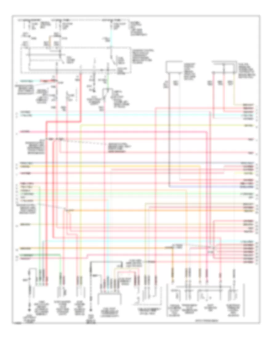
4.6L SOHC, Engine Performance Wiring Diagrams (1 of 3) for Ford Mustang 1999
 https://portal-diagnostov.com/license.html
Automotive Electricians Portal FZCO
Automotive Electricians Portal FZCO
https://portal-diagnostov.com/license.html
https://portal-diagnostov.com/license.html
Automotive Electricians Portal FZCO
Automotive Electricians Portal FZCOList of elements for 4.6L SOHC, Engine Performance Wiring Diagrams (1 of 3) for Ford Mustang 1999:
- (dash panel to headlamp junction harn, left side of engine compt)
- (engine control harn, right side of engine compt)
- (engine control sens & fuel charge harn, near breakout to fuel rail pressure transducer)
- (left rear side of transmission) digital transmission range (dtr) sensor
- (main harn, left kick panel)
- Accs input
- Air conditioning
- Anti- lock brakes
- Central junction box) (left of steering column)
- Ckp (+)
- Ckp (-)
- Cool fan
- Coolant fans system
- Cooling fans system
- Crankshaft position (ckp) sensor (center front of engine)
- Data link connector (dlc) (behind dash, right of column)
- Dlc
- Dlc (bus +)
- Dlc (bus -)
- Dtr tr1
- Dtr tr2
- Dtr tr4
- Ect sensor
- Egr vacuum
- Evap can pur
- Fp drv mod
- Fuse 15a
- Fuse 5a
- G100 (left front of engine compt)
- G203 (at right kick panel)
- Grd
- Ground
- Hot at all times
- Hot in run or start
- Iat sensor
- Ign coil 1
- Ign coil 3
- Ign coil 4
- Ign coil 5
- Ign coil 6
- Ignition coils
- Instrument cluster
- Lo fan out
- Maf sensor
- Module (pcm) (behind right kick panel)
- Nca
- Powertrain control
- Radio noise capacitors (top front of engine)
- Rr ho2s
- S134
- S135
- S170
- S171 (engine control sens & fuel charge harn, near breakout to fuel inj 4)
- S204
- S250
- S252
- S253
- S259
- S262
- Shft sol b
- Sht sol a
- System
- Tcc sol
- Tcs input
- Tft sensor
- Transmission control switch (tcs) (right of gear selector)
4.6L SOHC, Engine Performance Wiring Diagrams (2 of 3) for Ford Mustang 1999
 https://portal-diagnostov.com/license.html
Automotive Electricians Portal FZCO
Automotive Electricians Portal FZCO
https://portal-diagnostov.com/license.html
https://portal-diagnostov.com/license.html
Automotive Electricians Portal FZCO
Automotive Electricians Portal FZCOList of elements for 4.6L SOHC, Engine Performance Wiring Diagrams (2 of 3) for Ford Mustang 1999:
- (engine control sensor harn, right rear of engine compt)
- (engine control sensor harn, right side of dash, near grommet)
- (engine control sensor harn, right side of engine compt)
- (in trans control harn)
- (main harn, near central junction box)
- (top right side of fuel tank)
- 4r70w transmission
- Battery junction box (left side of engine compartment)
- Camshaft position (cmp) sensor (front of eng, near ign coil)
- Central junction box (left of steering column)
- Central junction box)
- Constant control relay module (inside right front fender, behind air filter housing)
- Cooling fans system
- Electronic pressure control (epc)
- Evap canister purge valve (right side of engine compt)
- Evap canister vent solenoid (rear of vehicle)
- Fuel pump assembly
- Fuel pump assembly shield
- Fuel pump driver module (underside of luggage compt)
- Fuel pump fuse 20a
- Fuel pump relay
- Fuel rail pressure transducer (top front of engine, behind ignition coil)
- Fuse 20a
- G100 (left front of engine compt)
- G101 (right front of engine compt)
- G400 (left
- Hot at all times
- Hot in run or start
- Inertia fuel shutoff switch (lower left rear corner of trunk)
- Mass airflow (maf) sensor (on rear of air cleaner assembly)
- Nca
- Pcm power relay
- Pcm pwr fuse 30a
- Rear of vehicle)
- Red
- Red/ pnk
- Red/pnk
- S100
- S108
- S116 (engine control sensor harn, near breakout to right front brake sensor)
- S117
- S126
- S169
- S224
- S234
- S250
- S266
- S451
- Shift solenoids (ss)
- Solenoid
- Torque converter clutch (tcc) solenoid
- Transmission fluid temperature sensor
4.6L SOHC, Engine Performance Wiring Diagrams (3 of 3) for Ford Mustang 1999
 https://portal-diagnostov.com/license.html
Automotive Electricians Portal FZCO
Automotive Electricians Portal FZCO
https://portal-diagnostov.com/license.html
https://portal-diagnostov.com/license.html
Automotive Electricians Portal FZCO
Automotive Electricians Portal FZCOList of elements for 4.6L SOHC, Engine Performance Wiring Diagrams (3 of 3) for Ford Mustang 1999:
- (engine control sens & fuel charge harn, right rear of engine compt) s157
- (engine control sensor & fuel charge harn) s158
- (engine control sensor & fuel charge harn, near fuel inj 7) s156
- (engine control sensor harn)
- (engine control sensor harn, near grommet)
- A/c cutout
- A/c hp sw
- A/c system
- Bpp
- Brake pedal position (bpp) switch (on brake pedal support)
- Central junction box (left of steering column)
- Cmp sens
- Cruise control system
- Differential pressure feedback egr (dpfe) sensor (center rear of engine compt)
- Dpfe
- Dtr tr3a
- Egr vacuum regulator (evr) solenoid (inside right fender)
- Engine coolant temperature (ect) sensor (top right front of engine)
- Epc sol
- Evap vent
- Fp mon
- Fr press
- Fuel inj 1
- Fuel inj 2
- Fuel inj 3
- Fuel inj 4
- Fuel inj 5
- Fuel inj 6
- Fuel inj 7
- Fuel inj 8
- Fuel injectors
- Fuel press
- Fuse 15a
- G100 (left front of engine compt)
- Hot at all times
- Iac valve
- Idle air control (iac) valve (top right side of engine)
- Ign coil 2
- Ign coil 7
- Ign coil 8
- Intake air temperature (iat) sensor (on air intake assembly)
- Left front heated oxygen sensor (ho2s) (in exhaust manifold, inboard side)
- Left rear heated oxygen sensor (ho2s) (left rear of engine, in exhaust man)
- Lf ho2s
- Lr ho2s
- Maf sens
- Module (pcm) (behind right kick panel)
- Nca
- Oss sens
- Output shaft speed sensor (left side of trans)
- Power
- Powertrain control
- Pwr gnd
- Red
- Red/pnk
- Ref volt
- Rf ho2s
- Right front heated oxygen sensor (ho2s) (in exhaust manifold, inboard side)
- Right rear heated oxygen sensor (ho2s) (in exhaust, rear of cat convert)
- Rr ho2s
- S120 (in trans harn)
- S121 (engine control harn, near grommet)
- S129
- S130 (engine control sensor harn)
- S164
- S200
- S207
- S250
- S275 (in main harn)
- Sig rtn
- Tan
- Tan/ red
- Tan/red
- Throttle position (tp) sensor (on throttle body)
- Tp sens
- Vss sig

 Čeština
 Dansk
Dansk Deutsch
 Ελληνικά
 English
 English
 Español
 Suomi
Suomi Français
 Français
 עברית
עברית Hrvatski
 Magyar
 Italiano
 日本語
日本語 Nederlands
 Polski
 Português
 Português
 Română
 Русский
 Slovenčina
 Slovenščina
 Svenska
 Türkçe
 中文 (中国)
