ENGINE PERFORMANCE
2.3L
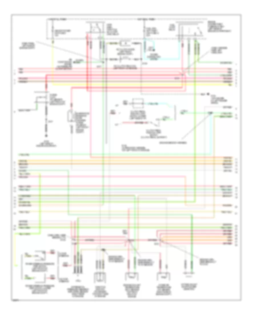
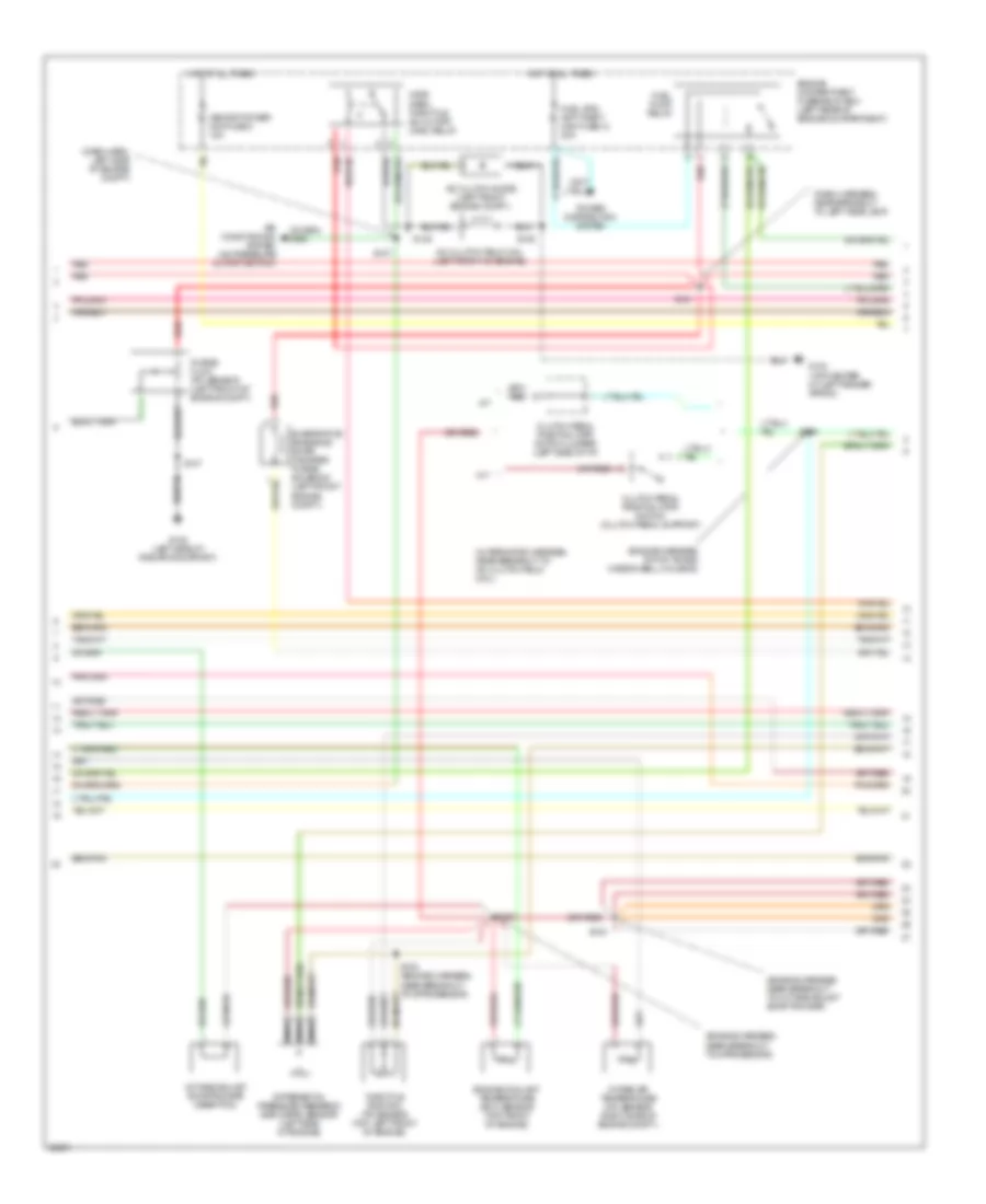
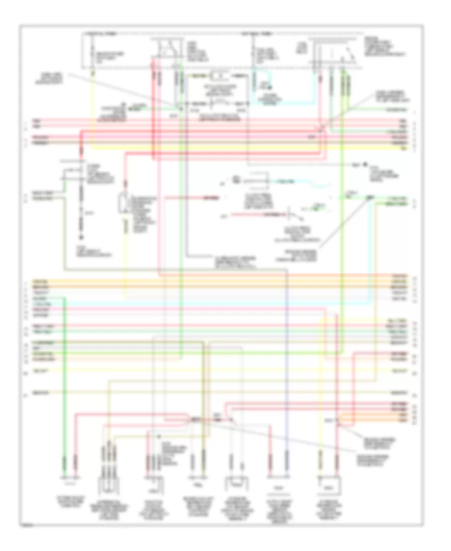
2.3L, Engine Performance Wiring Diagrams (1 of 4) for Ford Ranger Splash 1997
 https://portal-diagnostov.com/license.html
Automotive Electricians Portal FZCO
Automotive Electricians Portal FZCO
https://portal-diagnostov.com/license.html
https://portal-diagnostov.com/license.html
Automotive Electricians Portal FZCO
Automotive Electricians Portal FZCO
List of elements for 2.3L, Engine Performance Wiring Diagrams (1 of 4) for Ford Ranger Splash 1997:
- (case) ground
- (ckp) sensor (+)
- (ckp) sensor (-)
- (css) sol
- (dash harness, left side of engine compt)
- (ect) sensor
- (evr) ctrl
- (ho2s) #2
- (iat) sensor
- (left side of radiator support)
- (maf) sensor rtn
- (mil)
- (pf) sensor
- (psp) switch
- (pwr) ground
- (tft) sensor
- 4x4 indicator sw
- A/c psi cutoff
- C209
- C214
- C216
- Crankshaft position (ckp) sensor (lower right front of engine)
- Data link connector (dlc) (fastened to bottom of i/p, near steering column)
- Digital transmission range sensor
- Dlc
- Dlc bus (+)
- Dlc bus (-)
- Engine compartment fuse/relay box (left rear of engine compartment)
- Fuel pmp monitor
- Fuse 25a
- Fuse 7.5a
- G104 (top center of left fender apron)
- G108
- G123 (right side of safety wall)
- Hot at all times
- Hot in run or start
- I/p fuse panel (behind left side of i/p)
- Ignition coil #1
- Ignition coil #2
- Instrument cluster
- Instrument cluster system
- Malfunction indicator lamp (mil)
- Octane adjust
- Pcm power diode
- Pcm power maxi fuse 13 30a
- Pcm power relay
- Powertrain control module (pcm) (right rear of engine compartment, through safety wall)
- Primary coil (top right side of engine)
- Radio noise capacitor (near secondary coil)
- Red
- S101
- S106
- S107
- S110
- S118
- S134
- S144
- S147
- Secondary coil (top right front of engine)
- Sensor tr1
- Sensor tr2
- Sensor tr4
- Shift sol 1
- Shift sol 2
- Tachometer
- Tachometer test connector (left rear engine compt.)
- Trans ctrl (tcs)
- Transmission system (w/ manual shift: 4x4 indicator switch; w/ electric shift: generic electronic module)
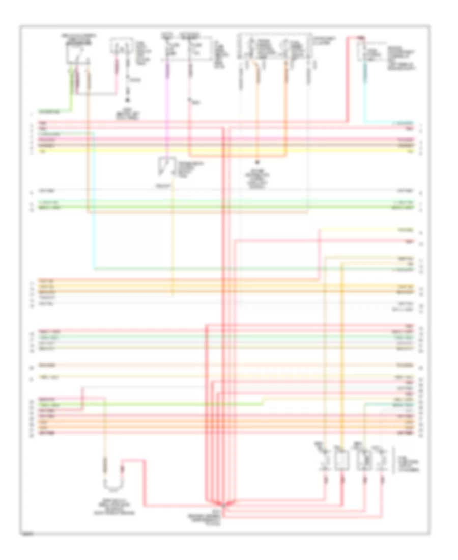
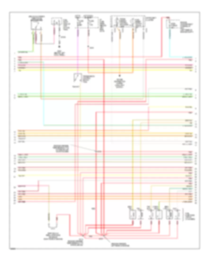
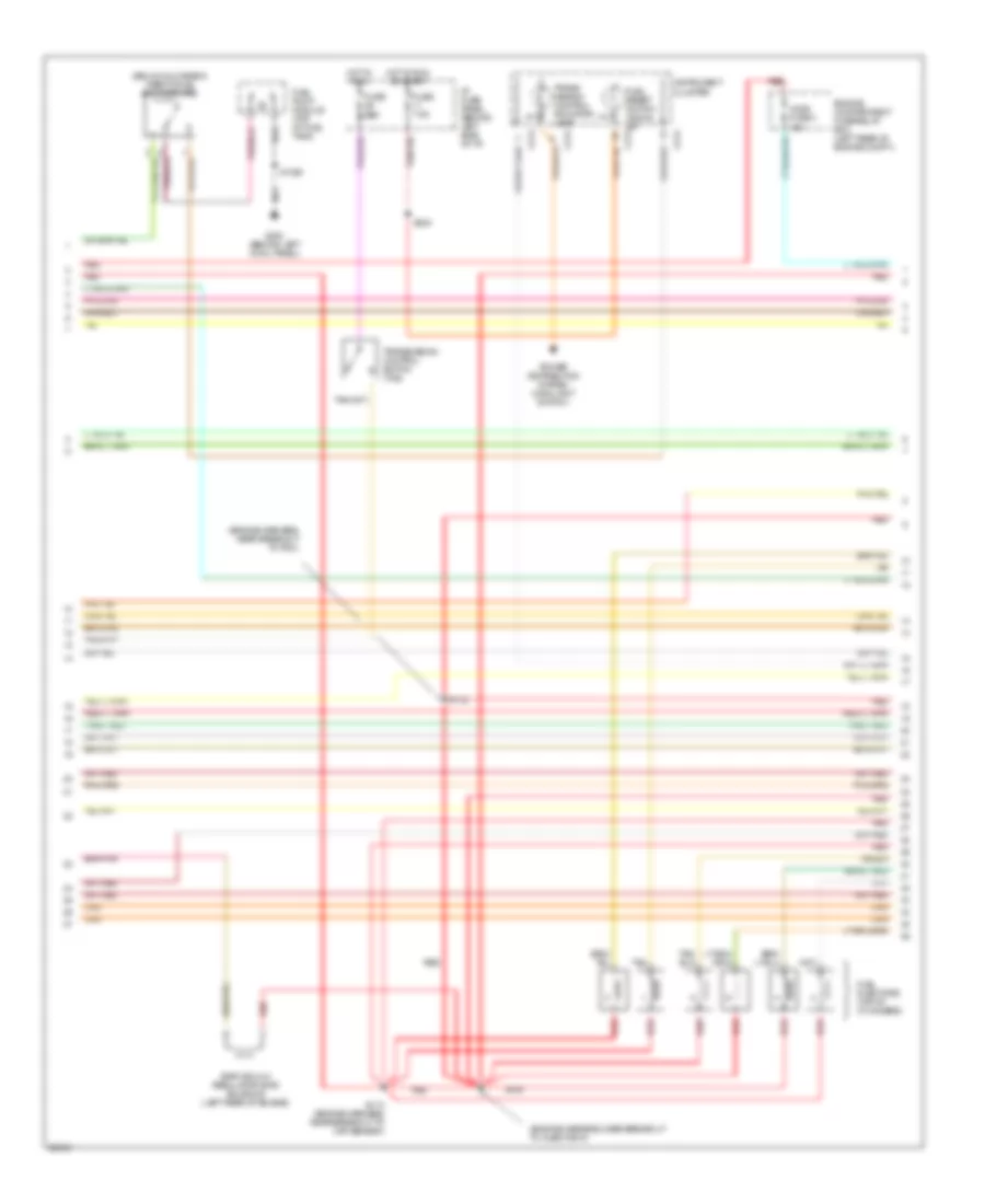
2.3L, Engine Performance Wiring Diagrams (2 of 4) for Ford Ranger Splash 1997
 https://portal-diagnostov.com/license.html
Automotive Electricians Portal FZCO
Automotive Electricians Portal FZCO
https://portal-diagnostov.com/license.html
https://portal-diagnostov.com/license.html
Automotive Electricians Portal FZCO
Automotive Electricians Portal FZCOList of elements for 2.3L, Engine Performance Wiring Diagrams (2 of 4) for Ford Ranger Splash 1997:
- (dash harn, near breakout to g102)
- (dash harness, near left headlamp)
- (dash panel, left side of engine compt)
- (engine harn, near breakout to g123)
- (engine harn, near breakout to iat sensor)
- (engine sensor harness)
- A/c clutch diode (left front engine compt.)
- A/c clutch field coil (left front of engine)
- A/t
- Air conditioning system (a/c pressure cutoff switch)
- Clutch pedal position (cpp) switch (clutch pedal support)
- Clutch pedal position (cpp) switch jumper (left side of i/p)
- Differential pressure feedback egr (dpfe) sensor (right rear of engine)
- Engine compartment fuse/relay box (left rear of engine compartment)
- Engine coolant temperature (ect) sensor (top right front of engine)
- Evaporative emissions (evap) canister purge solenoid (left front engine compt.)
- Fuel pump relay
- Fuel sys/ anti-theft maxi fuse 12 20a
- G104 (top center of left fender apron)
- G108 (left side of radiator support)
- Hot at all times
- Intake air temperature (iat) sensor (right side of engine compt.)
- M/t
- Memory power mini fuse 5 15a
- Nca
- Octane adjust shorting bar (near pcm)
- Power distribution system
- Power steering pressure (psp) switch (left front of engine compt.)
- Power steering pressure (psp) switch jumper (left front of engine compt.)
- Purge flow (pf) sensor (left front of engine compt.)
- Red
- S100
- S102
- S103
- S108
- S121
- S128
- S137
- S145 (alternator harness, top left front of engine)
- S146
- S147
- Throttle position (tp) sensor (top right side of engine)
- W/ pwr steering
- W/o pwr steering
- Wide open throttle a/c cutoff (wac) relay
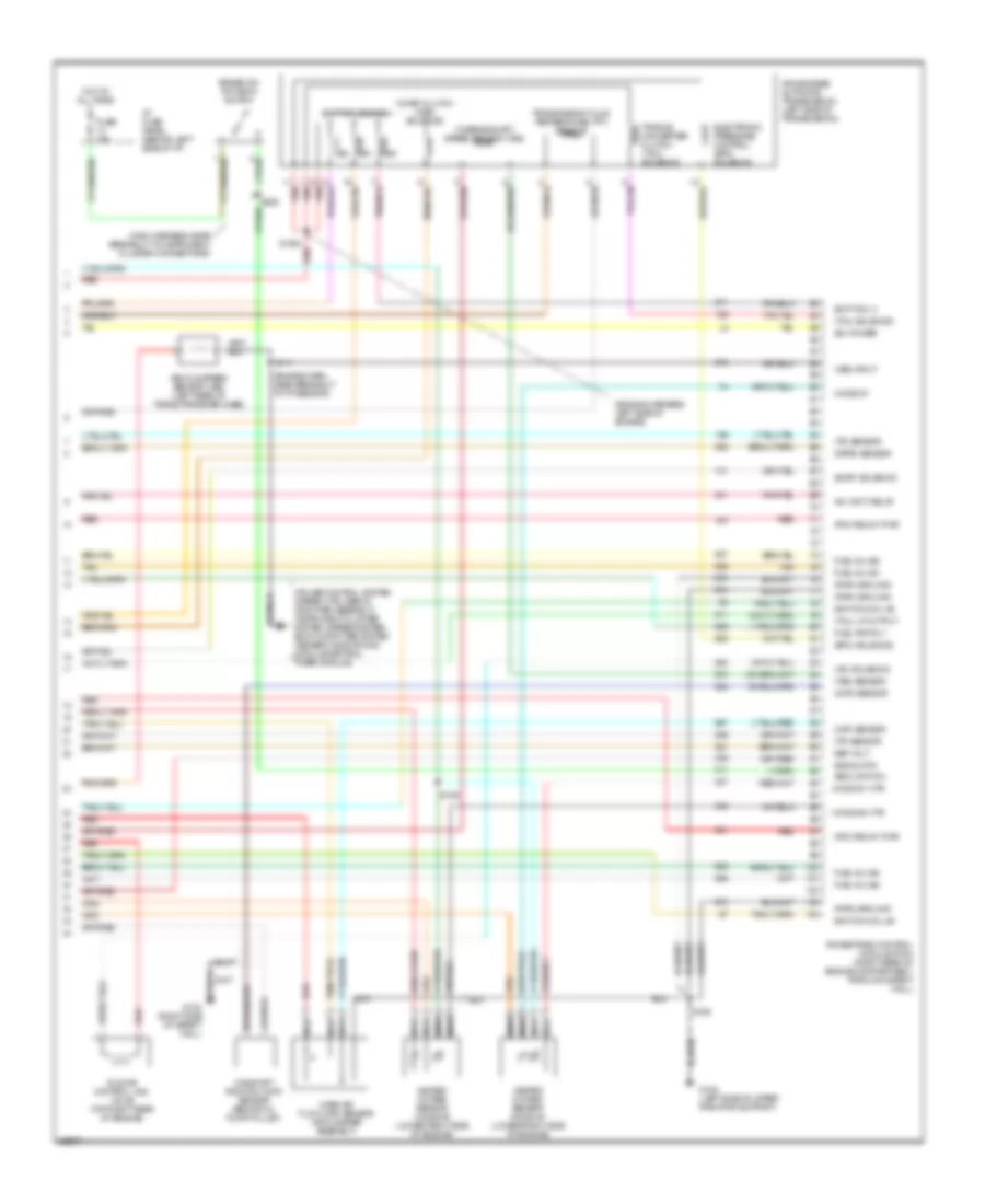
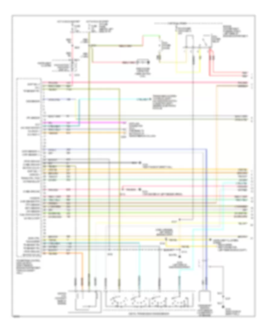
2.3L, Engine Performance Wiring Diagrams (3 of 4) for Ford Ranger Splash 1997
 https://portal-diagnostov.com/license.html
Automotive Electricians Portal FZCO
Automotive Electricians Portal FZCO
https://portal-diagnostov.com/license.html
https://portal-diagnostov.com/license.html
Automotive Electricians Portal FZCO
Automotive Electricians Portal FZCOList of elements for 2.3L, Engine Performance Wiring Diagrams (3 of 4) for Ford Ranger Splash 1997:
- (below glove box) inertia fuel shut-off (ifs)
- C214
- Egr vacuum regulator (evr) solenoid (right side of engine)
- Engine compartment fuse/relay box (left rear of engine compt.)
- Fuel injectors (top of cylinders)
- Fuel pump module (top of fuel tank)
- Fuel reset switch indica- or c214
- Fuse 15a
- Fuse 7.5a
- G200 (behind left cowl panel)
- Ho2s fuse 20 15a
- Hot in run
- Hot in run or start
- I/p fuse panel (behind left side of i/p)
- Instrument cluster
- Power distribution system (main light switch)
- Red
- S1005
- S104 (engine harness, near breakout to g123)
- S240
- Tan
- Trans- mission control indicator lamp
- Transmission control switch (tcs)
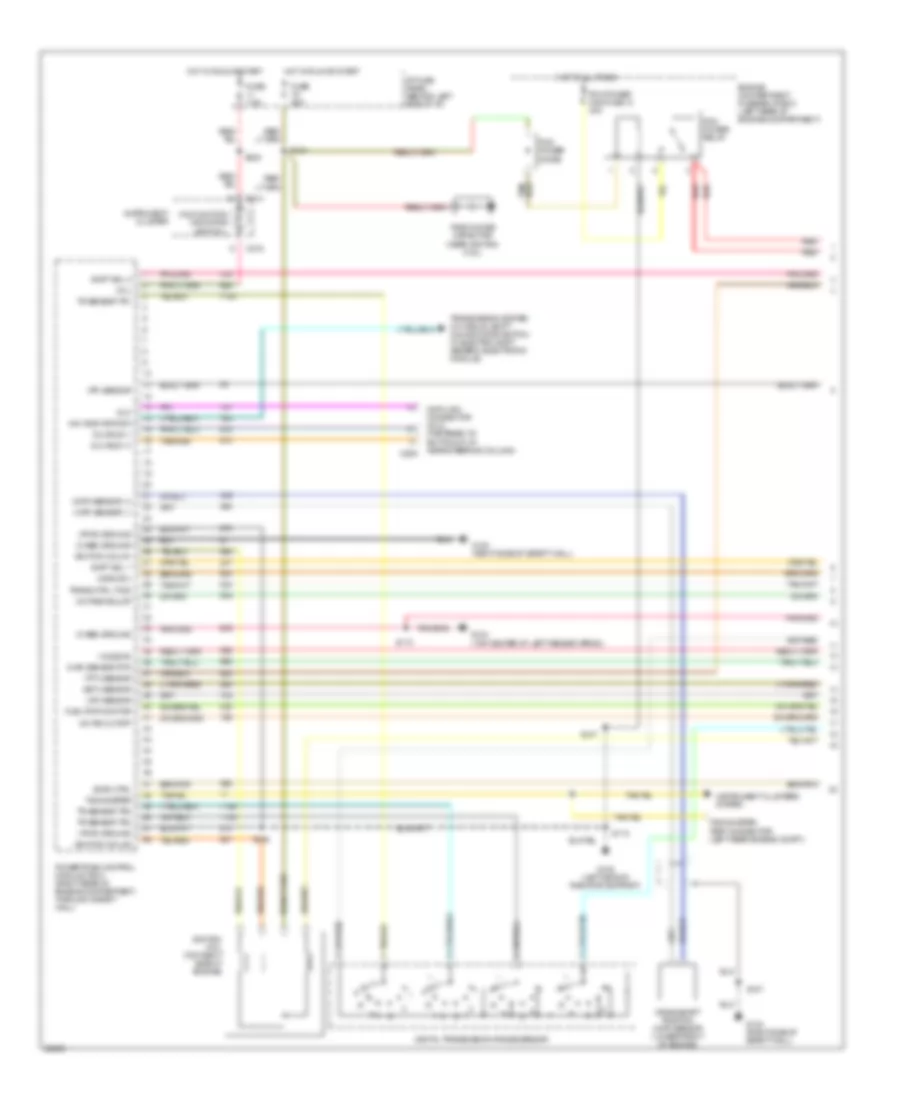
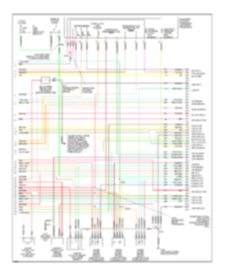
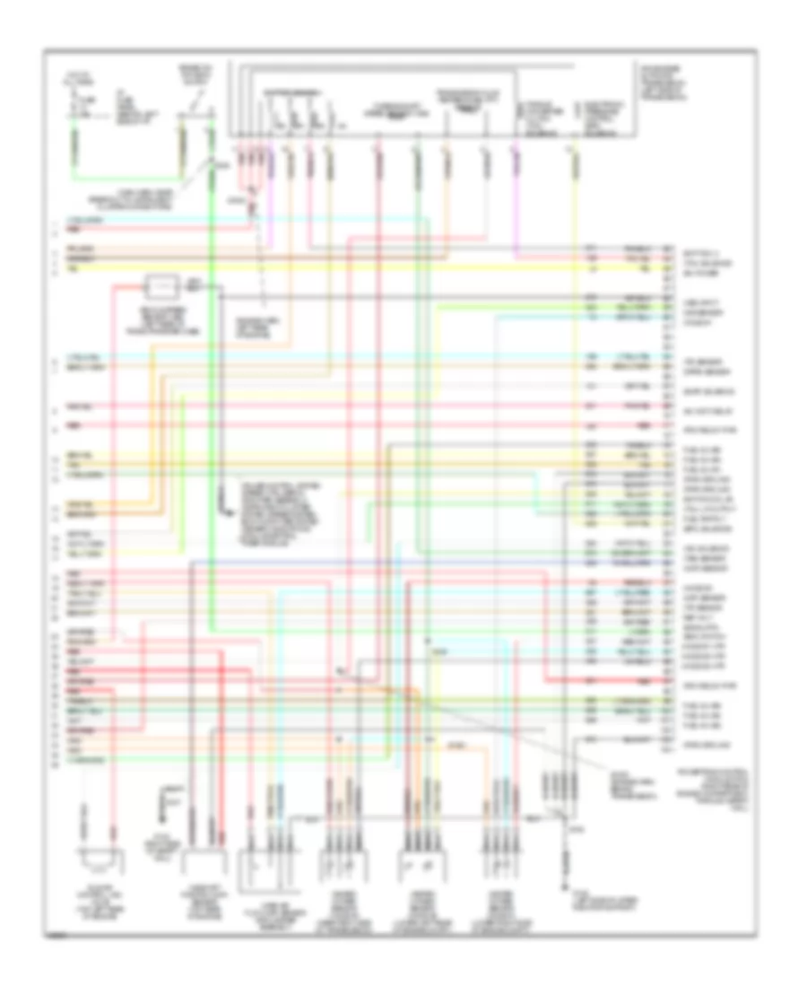
2.3L, Engine Performance Wiring Diagrams (4 of 4) for Ford Ranger Splash 1997
 https://portal-diagnostov.com/license.html
Automotive Electricians Portal FZCO
Automotive Electricians Portal FZCO
https://portal-diagnostov.com/license.html
https://portal-diagnostov.com/license.html
Automotive Electricians Portal FZCO
Automotive Electricians Portal FZCOList of elements for 2.3L, Engine Performance Wiring Diagrams (4 of 4) for Ford Ranger Splash 1997:
- (b+) power
- (boo) switch
- (cmp) sensor
- (dpfe) sensor
- (engine harn, near breakout to tp sensor)
- (engine harness, left side of engine)
- (epc) solenoid
- (evap) solenoid
- (ho2s) #1
- (ho2s) #1 htr
- (ho2s) #2 htr
- (iac) solenoid
- (maf) sensor
- (main harness, near breakout to instrument cluster connectors)
- (pcm relay) pwr
- (pwr) ground
- (tcc) solenoid
- (tcil) lp output
- (tp) sensor
- (tr) sensor
- (tss) sensor
- (vss) input
- 4r44e/4r55e automatic transmission (left side of transmission)
- A/c (wot) relay
- Brake on/ off (boo) switch
- Camshaft position (cmp) sensor (behind oil pump pulley)
- Coast clutch (css) solenoid
- Cruise control system (speed ctrl servo/ amplifier assembly), instrument cluster system (speedometer), body computer system (generic electronic module/central timer module)
- Electronic pressure control (epc) solenoid
- Fuel inj (#1)
- Fuel inj (#2)
- Fuel inj (#3)
- Fuel inj (#4)
- Fuel pmp rly
- Fuse 15a
- G108 (left side of upper radiator support)
- G123 (right side of safety wall)
- Heated oxygen sensor (ho2s) #1 (lower right side of engine)
- Heated oxygen sensor (ho2s) #2 (lower right side of engine)
- Hot at all times
- I/p fuse panel (behind left side of i/p)
- Idle air control (iac) valve (top right rear of engine)
- Ignition coil #3
- Ignition coil #4
- Mass air flow (maf) sensor (air cleaner assembly)
- Nca
- Powertrain control module (pcm) (right rear of engine compartment, through safety wall)
- Red
- Ref volt
- S1002 red
- S106
- S107
- S109
- S111
- S228
- Shift sol 3
- Shift solenoids
- Signal rtn
- Tan
- Torque converter clutch (tcc) solenoid
- Transmission fluid temperature (tft) sensor
- Turbine shaft speed sensor (tss)
- Vehicle speed sensor (vss) (left rear of trans./transfer case)
3.0L
3.0L, Engine Performance Wiring Diagrams (1 of 4) for Ford Ranger Splash 1997
 https://portal-diagnostov.com/license.html
Automotive Electricians Portal FZCO
Automotive Electricians Portal FZCO
https://portal-diagnostov.com/license.html
https://portal-diagnostov.com/license.html
Automotive Electricians Portal FZCO
Automotive Electricians Portal FZCOList of elements for 3.0L, Engine Performance Wiring Diagrams (1 of 4) for Ford Ranger Splash 1997:
- (case) ground
- (ckp) sensor (+)
- (ckp) sensor (-)
- (css) sol
- (ect) sensor
- (evr) ctrl
- (ho2s) #3
- (iat) sensor
- (maf) sensor rtn
- (mil)
- (pf) sensor
- (pwr) ground
- (tft) sensor
- 4x4 indicator sw
- A/c psi cutoff
- C209
- C214
- C216
- Crankshaft position (ckp) sensor (lower front of engine)
- Data link connector (dlc) (fastened to bottom of i/p, near steering column)
- Digital transmission range sensor
- Dlc
- Dlc bus (+)
- Dlc bus (-)
- Engine compartment fuse/relay box (left rear of engine compartment)
- Fuel pmp monitor
- Fuse 25a
- Fuse 7.5a
- G104 (top center of left fender apron)
- G108 (left side of radiator support)
- G123 (right side of safety wall)
- Hot at all times
- Hot in run or start
- I/p fuse panel (behind left side of i/p)
- Ignition coil #1
- Ignition coil #3
- Ignition coil (top right side of engine)
- Instrument cluster
- Instrument clusters system
- Malfunction indicator lamp (mil)
- Octane adjust
- Pcm power diode
- Pcm power maxi fuse 13 30a
- Pcm power relay
- Powertrain control module (pcm) (right rear of engine compartment, through safety wall)
- Radio noise capacitor (near ignition coil)
- Red
- S106
- S107
- S110
- S118
- S134
- S147
- S240
- Shift sol 1
- Shift sol 2
- Tachometer
- Tachometer test connector (left rear engine compt.)
- Tr sensor tr1
- Tr sensor tr2
- Tr sensor tr4
- Trans ctrl (tcs)
- Transmission system (w/ manual shift: 4x4 indicator switch; w/ electric shift: generic electronic module)
3.0L, Engine Performance Wiring Diagrams (2 of 4) for Ford Ranger Splash 1997
 https://portal-diagnostov.com/license.html
Automotive Electricians Portal FZCO
Automotive Electricians Portal FZCO
https://portal-diagnostov.com/license.html
https://portal-diagnostov.com/license.html
Automotive Electricians Portal FZCO
Automotive Electricians Portal FZCOList of elements for 3.0L, Engine Performance Wiring Diagrams (2 of 4) for Ford Ranger Splash 1997:
- (alternator harness, near breakout to a/c clutch field coil)
- (dash harn, left side of engine compt)
- (dash harness, near breakout to left headlamp)
- (engine harness, near breakout to dpfe sensor)
- (engine harness, near breakout to octane adjust shorting bar)
- (engine harness, top of trans- mission bell housing)
- A/c clutch diode (left front engine compt.)
- A/c clutch field coil (left front of engine)
- A/t
- Air conditioning system (a/c pressure cutoff switch)
- Clutch pedal position (cpp) switch (clutch pedal support)
- Clutch pedal position (cpp) switch jumper (left side of i/p)
- Differential pressure feedback egr (dpfe) sensor (left side of engine)
- Engine compartment fuse/relay box (left rear of engine compartment)
- Engine coolant temperature (ect) sensor (top front of engine)
- Evaporative emissions (evap) canister purge solenoid (left front engine compt.)
- Fuel pump relay
- Fuel sys/ anti-theft maxi fuse 12 20a
- G104 (top center of left fender apron)
- G108 (left side of radiator support)
- Hot at all times
- Intake air temperature (iat) sensor (right side of engine compt.)
- M/t
- Memory power mini fuse 5 15a
- Nca
- Octane adjust shorting bar (near pcm)
- Power distribution system
- Purge flow (pf) sensor (left front of engine compt.)
- Red
- S100 (engine harness, near breakout to dpfe sensor)
- S102
- S103
- S108
- S121
- S137
- S145
- S146
- S147
- Throttle position (tp) sensor (top left front of engine)
- Wide open throttle a/c cutoff (wac) relay
3.0L, Engine Performance Wiring Diagrams (3 of 4) for Ford Ranger Splash 1997
 https://portal-diagnostov.com/license.html
Automotive Electricians Portal FZCO
Automotive Electricians Portal FZCO
https://portal-diagnostov.com/license.html
https://portal-diagnostov.com/license.html
Automotive Electricians Portal FZCO
Automotive Electricians Portal FZCOList of elements for 3.0L, Engine Performance Wiring Diagrams (3 of 4) for Ford Ranger Splash 1997:
- (below glove box) inertia fuel shut-off (ifs)
- (engine harness, left rear of engine)
- (engine harness, near breakout to octane adjust shorting bar)
- C214
- Egr vacuum regulator (evr) solenoid (right side of engine)
- Engine compartment fuse/relay box (left rear of engine compt.)
- Fuel injectors (top of cylinders)
- Fuel pump module (top of fuel tank)
- Fuel reset switch indica- or c214
- Fuse 15a
- Fuse 7.5a
- G200 (behind left cowl panel)
- Ho2s fuse 20 15a
- Hot in run
- Hot in run or start
- I/p fuse panel (behind left side of i/p)
- Instrument cluster
- Power distribution system (main light switch)
- Red
- S1005
- S104
- S112
- S113 (engine harness, near breakout to evr solenoid)
- S240
- Tan
- Trans- mission control indicator lamp
- Transmission control switch (tcs)
3.0L, Engine Performance Wiring Diagrams (4 of 4) for Ford Ranger Splash 1997
 https://portal-diagnostov.com/license.html
Automotive Electricians Portal FZCO
Automotive Electricians Portal FZCO
https://portal-diagnostov.com/license.html
https://portal-diagnostov.com/license.html
Automotive Electricians Portal FZCO
Automotive Electricians Portal FZCOList of elements for 3.0L, Engine Performance Wiring Diagrams (4 of 4) for Ford Ranger Splash 1997:
- (b+) power
- (boo) switch
- (cmp) sensor
- (dpfe) sensor
- (engine harn, left rear of enigine)
- (epc) solenoid
- (evap) solenoid
- (ho2s) #1
- (ho2s) #1 htr
- (ho2s) #2
- (ho2s) #2 htr
- (ho2s) #3 htr
- (iac) solenoid
- (maf) sensor
- (main harn, near breakout to instrument cluster connectors)
- (pcm relay) pwr
- (pwr) ground
- (tcc) solenoid
- (tcil) lp output
- (tp) sensor
- (tr) sensor
- (tss) sensor
- (vss) input
- 4r44e/4r55e automatic transmission (left side of transmission)
- A/c (wot) relay
- Brake on/ off (boo) switch
- Camshaft position (cmp) sensor (top rear of engine)
- Coast clutch (css) solenoid
- Cruise control system (speed ctrl servo/ amplifier assembly), instrument cluster system (speedometer), body computer system (generic electronic module/central timer module)
- Electronic pressure control (epc) solenoid
- Fuel inj (#1)
- Fuel inj (#2)
- Fuel inj (#3)
- Fuel inj (#4)
- Fuel inj (#5)
- Fuel inj (#6)
- Fuel pmp rly
- Fuse 15a
- G108 (left side of upper radiator support)
- G123 (right side of safety wall)
- Heated oxygen sensor (ho2s) #1 (lower right side of engine compt.)
- Heated oxygen sensor (ho2s) #2 (lower left rear of engine compt.)
- Heated oxygen sensor (ho2s) #3 (near right side of transmission)
- Hot at all times
- I/p fuse panel (behind left side of i/p)
- Idle air control (iac) valve (top left front of engine)
- Ignition coil #2
- Mass air flow (maf) sensor (air cleaner assembly)
- Nca
- Powertrain control module (pcm) (right rear of engine compartment, through safety wall)
- Red
- Ref volt
- S1000 (engine harn, behind transmission)
- S1001
- S1002 red
- S106
- S107
- S109
- S111 (engine harness, left rear of engine)
- S228
- Shift sol 3
- Shift solenoids
- Signal rtn
- Tan
- Torque converter clutch (tcc) solenoid
- Transmission fluid temperature (tft) sensor
- Turbine shaft speed sensor (tss)
- Vehicle speed sensor (vss) (left rear of trans./transfer case)
4.0L
4.0L, Engine Performance Wiring Diagrams (1 of 4) for Ford Ranger Splash 1997
 https://portal-diagnostov.com/license.html
Automotive Electricians Portal FZCO
Automotive Electricians Portal FZCO
https://portal-diagnostov.com/license.html
https://portal-diagnostov.com/license.html
Automotive Electricians Portal FZCO
Automotive Electricians Portal FZCOList of elements for 4.0L, Engine Performance Wiring Diagrams (1 of 4) for Ford Ranger Splash 1997:
- (case) ground
- (ckp) sensor (+)
- (ckp) sensor (-)
- (css) sol
- (dash harness, left side of engine compt)
- (ect) sensor
- (evr) ctrl
- (ho2s) #3
- (iat) sensor
- (maf) sensor rtn
- (mil)
- (pf) sensor
- (pwr) ground
- (tft) sensor
- 4x4 indicator sw
- A/c psi cutoff
- C209
- C214
- C216
- Crankshaft position (ckp) sensor (lower front of engine)
- Data link connector (dlc) (fastened to bottom of i/p, near steering column)
- Digital transmission range sensor
- Dlc
- Dlc bus (+)
- Dlc bus (-)
- Engine compartment fuse/relay box (left rear of engine compartment)
- Fuel pmp monitor
- Fuse 25a
- Fuse 7.5a
- G104 (top center of left fender apron)
- G108 (left side of radiator support)
- G123 (right side of safety wall
- G123 (right side of safety wall)
- Hot at all times
- Hot in run or start
- I/p fuse panel (behind left side of i/p)
- Ignition coil #1
- Ignition coil #2
- Ignition coil (top right rear of engine)
- Instrument cluster
- Instrument clusters system
- Malfunction indicator lamp (mil)
- Octane adjust
- Oss sensor
- Pcm power diode
- Pcm power maxi fuse 13 30a
- Pcm power relay
- Powertrain control module (pcm) (right rear of engine compartment, through safety wall)
- Radio noise capacitor (near ignition coil)
- Red
- S106
- S107
- S110
- S118
- S134
- S144
- S147
- S240
- Shift sol 1
- Shift sol 2
- Tachometer
- Tachometer test connector (left rear engine compt.)
- Tr sensor tr1
- Tr sensor tr2
- Tr sensor tr4
- Trans ctrl (tcs)
- Transmission system (w/ manual shift: 4x4 indicator switch; w/ electric shift: generic electronic module)
4.0L, Engine Performance Wiring Diagrams (2 of 4) for Ford Ranger Splash 1997
 https://portal-diagnostov.com/license.html
Automotive Electricians Portal FZCO
Automotive Electricians Portal FZCO
https://portal-diagnostov.com/license.html
https://portal-diagnostov.com/license.html
Automotive Electricians Portal FZCO
Automotive Electricians Portal FZCOList of elements for 4.0L, Engine Performance Wiring Diagrams (2 of 4) for Ford Ranger Splash 1997:
- (alternator harness, near breakout to a/c clutch field coil)
- (dash harn, left side of engine compt)
- (dash harness, near breakout to left headlamp)
- (engine harness, near breakout to injector 5)
- (engine harness, near breakout to injector 6)
- (engine harness, top of trans- mission bell housing)
- A/c clutch diode (left front engine compt.)
- A/c clutch field coil (left front of engine)
- A/t
- Air conditioning system (a/c pressure cutoff switch)
- Clutch pedal position (cpp) switch (clutch pedal support)
- Clutch pedal position (cpp) switch jumper (left side of i/p)
- Differential pressure feedback egr (dpfe) sensor (left side of engine)
- Engine compartment fuse/relay box (left rear of engine compartment)
- Engine coolant temperature (ect) sensor (top front of engine)
- Evaporative emissions (evap) canister purge solenoid (left front engine compt.)
- Fuel pump relay
- Fuel sys/ anti-theft maxi fuse 12 20a
- G104 (top center of left fender apron)
- G108 (left side of radiator support)
- Hot at all times
- Intake air temperature (iat) sensor (front of engine, on air intake assembly)
- Intake air temperature sensor (on air intake assembly)
- M/t
- Memory power mini fuse 5 15a
- Nca
- Octane adjust shorting bar (near pcm)
- Output shaft (oss) speed sensor (near digital transmission sensor)
- Power distribution system
- Purge flow (pf) sensor (left front of engine compt.)
- Red
- S100 (engine harn, near break- out to dpfe sensor)
- S102
- S103
- S108
- S121
- S137
- S145
- S146
- S147
- Throttle position (tp) sensor (top left front of engine)
- Wide open throttle a/c cutoff (wac) relay
4.0L, Engine Performance Wiring Diagrams (3 of 4) for Ford Ranger Splash 1997
 https://portal-diagnostov.com/license.html
Automotive Electricians Portal FZCO
Automotive Electricians Portal FZCO
https://portal-diagnostov.com/license.html
https://portal-diagnostov.com/license.html
Automotive Electricians Portal FZCO
Automotive Electricians Portal FZCOList of elements for 4.0L, Engine Performance Wiring Diagrams (3 of 4) for Ford Ranger Splash 1997:
- (below glove box) inertia fuel shut-off (ifs)
- (engine harness, near breakout to injector 5)
- (engine harness, near breakout to pcm)
- C214
- Egr vacuum regulator (evr) solenoid (left rear of engine)
- Engine compartment fuse/relay box (left rear of engine compt.)
- Fuel injectors (top of cylinders)
- Fuel pump module (top of fuel tank)
- Fuel reset switch indica- or c214
- Fuse 15a
- Fuse 7.5a
- G200 (behind left cowl panel)
- Ho2s fuse 3 15a
- Hot in run
- Hot in run or start
- I/p fuse panel (behind left side of i/p)
- Instrument cluster
- Power distribution system (main light switch)
- Red
- S1005
- S104
- S112
- S113 (engine harness, near breakout to maf sensor)
- S240
- Tan
- Trans- mission control indicator lamp
- Transmission control switch (tcs)
4.0L, Engine Performance Wiring Diagrams (4 of 4) for Ford Ranger Splash 1997
 https://portal-diagnostov.com/license.html
Automotive Electricians Portal FZCO
Automotive Electricians Portal FZCO
https://portal-diagnostov.com/license.html
https://portal-diagnostov.com/license.html
Automotive Electricians Portal FZCO
Automotive Electricians Portal FZCOList of elements for 4.0L, Engine Performance Wiring Diagrams (4 of 4) for Ford Ranger Splash 1997:
- (b+) power
- (boo) switch
- (cmp) sensor
- (dpfe) sensor
- (engine harn, left rear of engine)
- (epc) solenoid
- (evap) solenoid
- (ho2s) #1
- (ho2s) #1 htr
- (ho2s) #2
- (ho2s) #2 htr
- (ho2s) #3 htr
- (iac) solenoid
- (maf) sensor
- (main harn, near breakout to instrument cluster connectors)
- (pcm relay) pwr
- (pwr) ground
- (tcc) solenoid
- (tcil) lp output
- (tp) sensor
- (tr) sensor
- (tss) sensor
- (vss) input
- 4r44e/4r55e automatic transmission (left side of transmission)
- A/c (wot) relay
- Brake on/ off (boo) switch
- Camshaft position (cmp) sensor (top rear of engine)
- Cruise control system (speed ctrl servo/ amplifier assembly), instrument cluster system (speedometer), body computer system (generic electronic module/central timer module)
- Electronic pressure control (epc) solenoid
- Fuel inj (#1)
- Fuel inj (#2)
- Fuel inj (#3)
- Fuel inj (#4)
- Fuel inj (#5)
- Fuel inj (#6)
- Fuel pmp rly
- Fuse 15a
- G108 (left side of upper radiator support)
- G123 (right side of safety wall)
- Heated oxygen sensor (ho2s) #1 (lower right side of engine compt.)
- Heated oxygen sensor (ho2s) #2 (lower left rear of engine compt.)
- Heated oxygen sensor (ho2s) #3 (near right side of transmission)
- Hot at all times
- I/p fuse panel (behind left side of i/p)
- Idle air control (iac) valve (top left rear of engine)
- Ignition coil #3
- Mass air flow (maf) sensor (air cleaner assembly)
- Nca
- Ods sensor
- Powertrain control module (pcm) (right rear of engine compartment, through safety wall)
- Red
- Ref volt
- S1000 (engine harn, behind transmission)
- S1001
- S1002
- S106
- S107
- S109
- S228
- Shift sol 3
- Shift solenoids
- Signal rtn
- Tan
- Torque converter clutch (tcc) solenoid
- Transmission fluid temperature (tft) sensor
- Turbine shaft speed sensor (tss)
- Vehicle speed sensor (vss) (left rear of trans./transfer case)

 Čeština
 Dansk
Dansk Deutsch
 Ελληνικά
 English
 English
 Español
 Suomi
Suomi Français
 Français
 עברית
עברית Hrvatski
 Magyar
 Italiano
 日本語
日本語 Nederlands
 Polski
 Português
 Português
 Română
 Русский
 Slovenčina
 Slovenščina
 Svenska
 Türkçe
 中文 (中国)
