POWER DISTRIBUTION
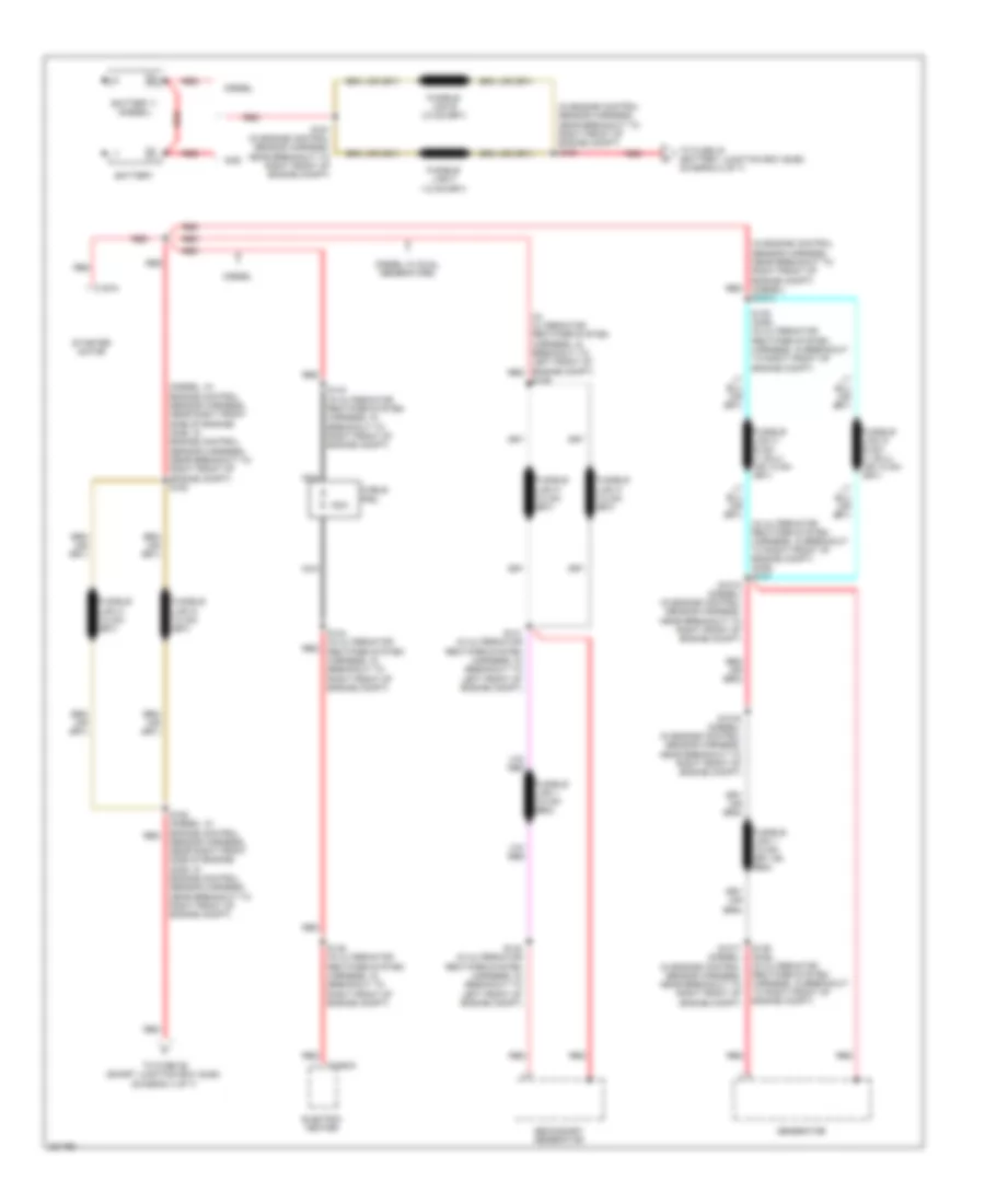
Power Distribution Wiring Diagram (1 of 7) for Ford Cab & Chassis F350 Super Duty 2008
 https://portal-diagnostov.com/license.html
Automotive Electricians Portal FZCO
Automotive Electricians Portal FZCO
https://portal-diagnostov.com/license.html
https://portal-diagnostov.com/license.html
Automotive Electricians Portal FZCO
Automotive Electricians Portal FZCO
List of elements for Power Distribution Wiring Diagram (1 of 7) for Ford Cab & Chassis F350 Super Duty 2008:
- (diesel: in engine control sensor harness, near right front side of engine) (gas: in engine control sensor harness, near breakout to right front of engine compt) s153
- (in alternator rectifier system harness, in breakout to left front of engine compt) red
- (in alternator rectifier system harness, in breakout to right front of engine compt) (gas) s137
- (in engine control sensor harness, near breakout to right front of engine compt) (diesel) s1014
- (in engine control sensor harness, near breakout to right front of engine compt) s160
- 150a
- Battery
- Battery ii (diesel)
- C197a
- C2463a
- Cable pro
- Diesel
- Diesel w/ dual generators
- Electric heater
- Gas
- Generator
- Nca
- Red
- S1015 (diesel) (in engine control sensor harness, near breakout to right front of engine compt)
- S1016 (diesel) (in engine control sensor harness, near breakout to right front of engine compt)
- S1017 (diesel) (in engine control sensor harness, near breakout to right front of engine compt)
- S138 (gas) (in alternator rectifier system harness, in breakout to right front of engine compt)
- S139
- S139 (gas) (in alternator rectifier system harness, in breakout to right front of engine compt)
- S140 (in alternator rectifier system harness, in breakout to left front of engine compt)
- S141 (in alternator rectifier system harness, in breakout to left front of engine compt)
- S143 (in alternator rectifier system harness, in breakout to right front of engine compt)
- S144 (in alternator rectifier system harness, in breakout to right front of engine compt)
- S145 (in alternator rectifier system harness, in breakout to right front of engine compt)
- S152 (diesel: in engine control sensor harness, near right front side of engine) (gas: in engine control sensor harness, near breakout to right front of engine compt)
- S161 (in engine control sensor harness, near breakout to right front of engine compt)
- Secondary generator
- Starter motor
- To fuse 26 (smart junction box (sjb)) (diagram 4 of 7)
- To fuse 40 (battery junction box (bjb)) (diagram 2 of 7)
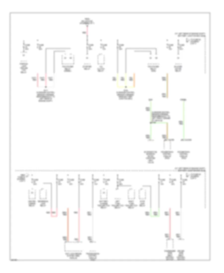
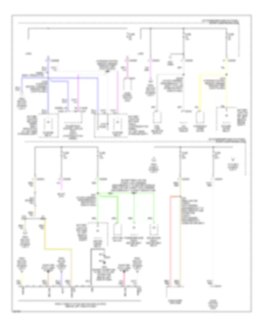
Power Distribution Wiring Diagram (2 of 7) for Ford Cab & Chassis F350 Super Duty 2008
 https://portal-diagnostov.com/license.html
Automotive Electricians Portal FZCO
Automotive Electricians Portal FZCO
https://portal-diagnostov.com/license.html
https://portal-diagnostov.com/license.html
Automotive Electricians Portal FZCO
Automotive Electricians Portal FZCOList of elements for Power Distribution Wiring Diagram (2 of 7) for Ford Cab & Chassis F350 Super Duty 2008:
- (at left rear of engine compt) battery junction box (bjb)
- (in engine control sensor harness, near breakout to left front corner of vehicle) s158
- A/c clutch relay
- Anti-lock brake system (abs) module
- Battery charge trailer tow relay
- Blower motor relay
- C1232b
- Diesel
- Driver side seat control switch
- Evaporative emission (evap) canister vent valve
- From c fuse 24 (diagram 2 of 7)
- From splice s160 (diagram 1 of 7)
- Fuse 10a
- Fuse 15a
- Fuse 20a
- Fuse 25a
- Fuse 30a
- Fuse 40a
- Fuse 50a
- Gas
- Heated mirror relay
- Left turn trailer tow relay
- Parking lamp trailer tow relay
- Passenger side seat control switch
- Pcm power relay (diesel)
- Pcm power relay (gas)
- Powertrain control module (pcm)
- Red
- Reversing lamp relay
- Right turn trailer tow relay
- S117 (in engine control sensor harness, near breakout to left rear of engine compt)
- S154 (in engine control sensor harness, near battery junction box)
- Starter relay
- Stop lamp relay
- To fuse 28 (diagram 2 of 7)
- To fuse 49 (diagram 3 of 7)
- Transmission control module (tcm)
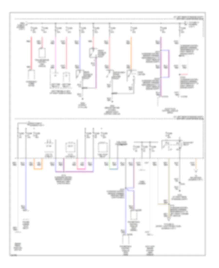
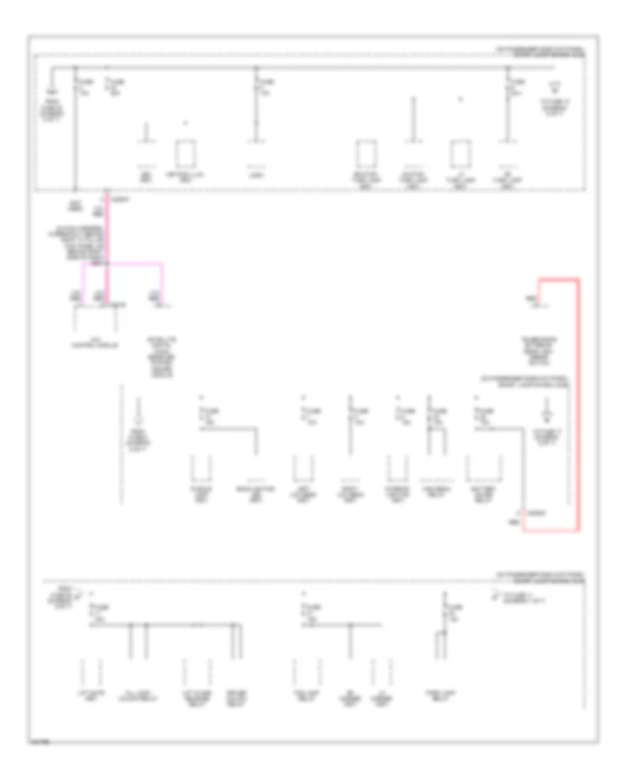
Power Distribution Wiring Diagram (3 of 7) for Ford Cab & Chassis F350 Super Duty 2008
 https://portal-diagnostov.com/license.html
Automotive Electricians Portal FZCO
Automotive Electricians Portal FZCO
https://portal-diagnostov.com/license.html
https://portal-diagnostov.com/license.html
Automotive Electricians Portal FZCO
Automotive Electricians Portal FZCOList of elements for Power Distribution Wiring Diagram (3 of 7) for Ford Cab & Chassis F350 Super Duty 2008:
- (at left rear of engine compt) battery junction box (bjb)
- (in engine control sensor harness, near breakout to right rear of engine compt) s103
- Anti-lock brake system (abs) module
- Brake pedal position switch
- C1232b
- C1273a
- C1273b
- C175b
- Cigar lighter
- From d fuse 45 (diagram 2 of 7)
- From fuse 47 (diagram 3 of 7)
- Front console power point
- Fuel pump motor diode
- Fuel pump relay
- Fuse 10a
- Fuse 15a
- Fuse 20a
- Fuse 2a
- Fuse 30a
- Fuse 40a
- Fuse 50a
- Fuse 5a
- G103 (at right rear of engine compt)
- G203 (behind center of dash, behind audio control module)
- G302 (in right "a" pillar)
- Glow plug control module (gpcm)
- Hi to low relay
- Instrument panel power point
- Low to hi relay
- Power mirror fold relay
- Powertrain control module (pcm) (diesel)
- Powertrain control module (pcm) (gas)
- Rear console power point
- Red
- Run/start relay
- S1000 (in engine control sensor harness, near breakout to right rear of engine compt)
- S1003 (in engine control sensor harness, near breakout to right rear of engine compt)
- S118 (in engine control sensor harness, near battery junction box)
- S119 (in engine control sensor harness, near breakout to left front corner of vehicle)
- S123 (in engine control sensor harness, near battery junction box)
- S124 (in engine control sensor harness, near breakout to right rear of engine compt)
- S162
- S225
- S323
- To fuse 13 (diagram 3 of 7)
- To fuse 33 (smart junction box (sjb)) (diagram 4 of 7)
- To splice s233 (diagram 4 of 7)
- Trailer brake control (tbc) module
- Upfitter relay 1
- Upfitter relay 2
- Upfitter relay box (at right side of dash)
- Video camera
- Windshield wiper motor
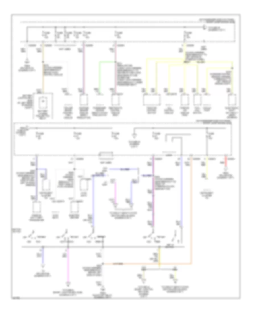
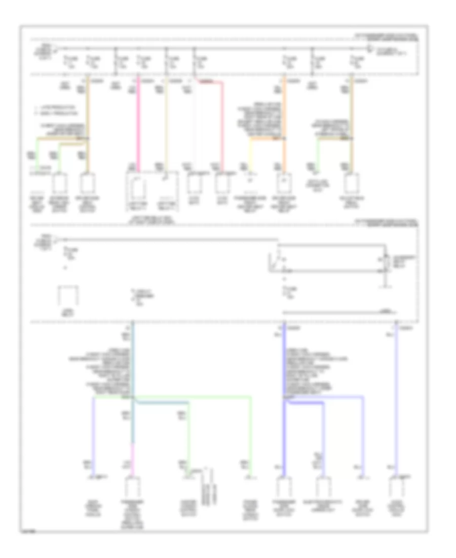
Power Distribution Wiring Diagram (4 of 7) for Ford Cab & Chassis F350 Super Duty 2008
 https://portal-diagnostov.com/license.html
Automotive Electricians Portal FZCO
Automotive Electricians Portal FZCO
https://portal-diagnostov.com/license.html
https://portal-diagnostov.com/license.html
Automotive Electricians Portal FZCO
Automotive Electricians Portal FZCOList of elements for Power Distribution Wiring Diagram (4 of 7) for Ford Cab & Chassis F350 Super Duty 2008:
- (not used)
- (on passenger side kick panel) smart junction box (sjb)
- 4x4 control module
- Acc
- Battery charge trailer tow relay
- Battery junction box (bjb) (at left rear of engine compt)
- C2280a
- C2280b
- C2280d
- C2280e
- C2280h
- C2357a
- C2463c
- C281b
- Compass sensor module (early production)
- Electric heater
- Electronic shift on the fly (esof) solenoid
- From h fuse 35 (diagram 4 of 7)
- From run/start relay (diagram 3 of 7)
- From splice s119 (diagram 3 of 7)
- From splice s152 (diagram 1 of 7)
- Fuse 10a
- Fuse 20a
- Fuse 5a
- Fuse 7.5a
- Hvac eatc
- Hvac emtc
- Ignition switch
- Instrument cluster (ic)
- Key in switch
- Logic
- Off
- Parking aid module (pam)
- Passenger air bag deactivation (pad) switch
- Passive anti-theft transceiver
- Red
- Restraints control module (rcm)
- Run
- S105 (in engine control sensor harness, in breakout to left rear of engine compt)
- S206 (in main harness, near breakout to right side of hvac housing)
- S216 (in main harness, near breakout behind audio control module)
- S223 (in main harness, near breakout behind left side of dash, left of radio opening)
- S233 (in main harness, near breakout behind left side of dash)
- S240 (in main harness, near breakout on front of steering column, near bottom)
- S314 (regular cab: in body main harness, near breakout to center of cab floor, near rear of cab) (super cab: in body main harness, near breakout under passenger seat)
- Start
- To circuit deactivation ignition module (cdim) (diagram 5 of 7)
- To fuse 36 (diagram 4 of 7)
- To fuse 38 (diagram 5 of 7)
- To fuse 43 (smart junction box (sjb)) (diagram 5 of 7)
- To fuse 44 (smart junction box (sjb)) (diagram 5 of 7)
- To splice s126 (diagram 5 of 7)
- Towl haul switch
- Traction control switch
- Trailer brake control (tbc) module
- Vacuum pump
- W/ cdim
- W/o cdim
Power Distribution Wiring Diagram (5 of 7) for Ford Cab & Chassis F350 Super Duty 2008
 https://portal-diagnostov.com/license.html
Automotive Electricians Portal FZCO
Automotive Electricians Portal FZCO
https://portal-diagnostov.com/license.html
https://portal-diagnostov.com/license.html
Automotive Electricians Portal FZCO
Automotive Electricians Portal FZCOList of elements for Power Distribution Wiring Diagram (5 of 7) for Ford Cab & Chassis F350 Super Duty 2008:
- (diesel)
- (except regular cab: in body main harness, near breakout to center console) (regular cab: in body main harness, near breakout to right rear of cab) s310
- (gas)
- (in engine control sensor harness, near battery junction box) s157
- (not used)
- (on passenger side kick panel) smart junction box (sjb)
- 4x4 control module
- Audio control module (acm)
- Batt
- Battery junction box (bjb) (at left rear of engine compt)
- Battery junction box (bjb) (diesel early production) (at left rear of engine compt)
- Battery junction box (bjb) (gas & late production diesel) (at left rear of engine compt)
- Blower motor relay
- C1232b
- C175t
- C2280a
- C2280b
- C2280d
- C2280e
- C240a
- C281b
- Circuit deactivation ignition module (cdim) (behind left side of dash)
- Computer data lines system
- Diesel early production
- Driver side front heated seat relay
- From fuse 27 (diagram 4 of 7)
- From ignition switch (diagram 4 of 7)
- From splice s240 (diagram 4 of 7)
- Fuel tank selector switch
- Fuse 10a
- Fuse 20a
- Fuse 5a
- G300 (except super cab: in left "a" pillar) (super cab: behind left side of dash)
- Gnd
- Heated mirror relay
- Logic
- Ms can+
- Ms can-
- Otis diode
- Passenger side front heated seat relay
- Powertrain control module (pcm) (gas & late production diesel)
- Run in
- S104 (in engine control sensor harness, near battery junction box)
- S126 (in engine control harness, near battery junction box)
- S201 (in main harness, near breakout behind right side of dash)
- S224
- S2439 (in main harness, near breakout to right "a" pillar or behind right side of dash)
- S321 (regular cab: in body main harness, near breakout to right rear of cab) (super cab: in body main harness, near breakout under driver seat)
- Starter relay
- Subwoofer amplifier
- To fuse 2 (diagram 6 of 7)
- Upfitter switch
- W/ cdim
- W/o cdim
- Windshield wiper motor
Power Distribution Wiring Diagram (6 of 7) for Ford Cab & Chassis F350 Super Duty 2008
 https://portal-diagnostov.com/license.html
Automotive Electricians Portal FZCO
Automotive Electricians Portal FZCO
https://portal-diagnostov.com/license.html
https://portal-diagnostov.com/license.html
Automotive Electricians Portal FZCO
Automotive Electricians Portal FZCOList of elements for Power Distribution Wiring Diagram (6 of 7) for Ford Cab & Chassis F350 Super Duty 2008:
- (in main harness, in breakout behind right "a" pillar kick panel or behind right side of dash) s204
- (not used)
- (on passenger side kick panel) smart junction box (sjb)
- 4x4 control module
- All lock/ unlock relay
- Backlighting led (fet)
- Battery saver relay
- Bs1 (fet)
- C2280a
- C2280d
- Driver unlock relay
- Fog lamp relay
- From fuse 25 r (diagram 6 of 7)
- From fuse 39 (diagram 5 of 7)
- From fuse 6 (diagram 6 of 7)
- Fuse 10a
- Fuse 15a
- Fuse 20a
- High beam relay
- Interior lighting (fet)
- Keypad illum (fet)
- Left low beam (fet)
- Lf turn lamp (fet)
- Lh corner (fet)
- Lift gate (fet)
- Lift glass release relay
- Logic
- Lr stop/ turn lamp (fet)
- Park lamp relay
- Puddle lamp (fet)
- Red
- Rf turn lamp (fet)
- Rh corner (fet)
- Right low beam (fet)
- Rr stop/ turn lamp (fet)
- Satellite digital audio receiver system (sdars) module
- Telescoping exterior rear view mirror switch
- To fuse 10 (diagram 6 of 7)
- To fuse 11 (diagram 7 of 7)
- To fuse 17 (diagram 6 of 7)
Power Distribution Wiring Diagram (7 of 7) for Ford Cab & Chassis F350 Super Duty 2008
 https://portal-diagnostov.com/license.html
Automotive Electricians Portal FZCO
Automotive Electricians Portal FZCO
https://portal-diagnostov.com/license.html
https://portal-diagnostov.com/license.html
Automotive Electricians Portal FZCO
Automotive Electricians Portal FZCOList of elements for Power Distribution Wiring Diagram (7 of 7) for Ford Cab & Chassis F350 Super Duty 2008:
- (crew cab: in body main harness, near breakout across floor) (regular cab: in body main harness, near breakout to right "b" pillar) (super cab: in body main harness, near breakout to right rear door) s303
- (crew cab: in body main harness, near breakout across floor) (regular cab: in body main harness, near breakout to right "b" pillar) (super cab: in body main harness, near breakout under passenger seat) s301
- (in body main harness, near breakout under driver seat) s317
- (in main harness, near breakout to left spoke of steering wheel) s228
- (not used)
- (on passenger side kick panel) smart junction box (sjb)
- (regular cab: in body main harness, near breakout to right rear of cab) (except regular cab: in body main harness, near breakout to center console) s311
- Accessory delay relay
- Adjustable pedal switch
- Audio control module (acm)
- C2280a
- C2280b
- C2280d
- C228a
- C2357a
- C240a
- C341b
- C341c
- C921a
- Circuit breaker 30a
- Crew cab
- Data link connector (dlc)
- Driver seat module (dsm)
- Driver side door lock switch
- Driver side front heated seat relay
- Driver side seat control switch
- Early production
- Electrochromatic inside mirror unit
- Exterior rear view mirror switch
- From fuse 20 t (diagram 7 of 7)
- From fuse 22 s (diagram 6 of 7)
- Fuse 10a
- Fuse 15a
- Fuse 20a
- Fuse 25a
- Fuse 7.5a
- Horn relay
- Hvac eatc
- Hvac emtc
- Late production
- Logic
- Master window control switch
- Passenger side door lock switch
- Passenger side front heated seat relay
- Passenger side window control switch (regular & super cab)
- Power sliding rear window switch
- Regular & super cab
- Roof opening panel module
- To fuse 24 (diagram 7 of 7)
- Upfitter relay 3
- Upfitter relay 4
- Upfitter relay box (at right side of dash)

 Čeština
 Dansk
Dansk Deutsch
 Ελληνικά
 English
 English
 Español
 Suomi
Suomi Français
 Français
 עברית
עברית Hrvatski
 Magyar
 Italiano
 日本語
日本語 Nederlands
 Polski
 Português
 Português
 Română
 Русский
 Slovenčina
 Slovenščina
 Svenska
 Türkçe
 中文 (中国)
