POWER DISTRIBUTION
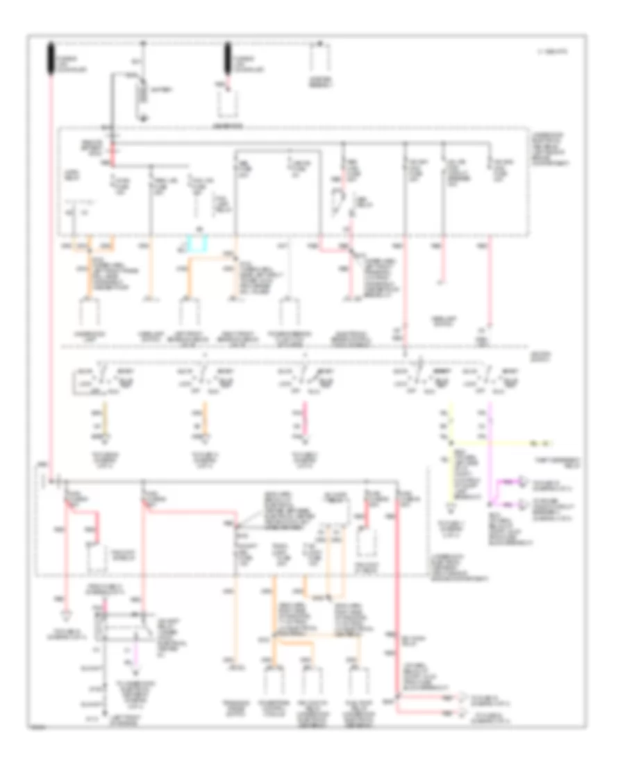
Power Distribution Wiring Diagram (1 of 4) for Oldsmobile Cutlass Supreme SL 1997
 https://portal-diagnostov.com/license.html
Automotive Electricians Portal FZCO
Automotive Electricians Portal FZCO
https://portal-diagnostov.com/license.html
https://portal-diagnostov.com/license.html
Automotive Electricians Portal FZCO
Automotive Electricians Portal FZCO
List of elements for Power Distribution Wiring Diagram (1 of 4) for Oldsmobile Cutlass Supreme SL 1997:
- (diagram 3 of 4)
- (eng harn, below u/h electrical center, between electrical center and eng coolant level ind mod)
- (eng harn, right side of radiator, 10 cm from u/h electrical center #1)
- (eng harn, right side of radiator, 17 cm from u/h electrical center #1)
- (i/p harn, below i/p compt, 16 cm from fuse block breakout)
- (left front of engine)
- (wiper harn, left front frame rail, 4 cm from windshield washer pump breakout) c2
- 1995 vftc c
- A/c cmpr relay
- A/c cont fuse 10a
- Abs fuse 20a
- Abs maxi- fuse 60a
- Abs relay
- Accy
- B/h conn pin k1
- B10
- Battery
- Bulb test
- Ecm bat fuse 20a
- Electronic brake control module (ebcm)
- Fan cont #1 relay
- Fan cont #1 relay (underhood electrical center #1)
- Fan cont #2 relay
- Fog lamp relay
- Fog lps fuse 10a
- From fuse 12 (diagram 2 of 4)
- Fuel pump relay (underhood electrical center #1)
- Fusible link (20 ga-rust)
- G110
- Generator
- Hd lps maxi circuit breaker 30a
- Headlamp switch
- Horn fuse 15a
- Horn relay
- Ign sw1 maxi- fuse 40a
- Ign sw2 maxi- fuse 40a
- Ign syst relay (under- hood electrical center #1)
- Ignition switch
- Left front brake solenoid valve
- Left side of i/p compt, 6 cm from i/p compt lamp breakout)
- Lock
- Maxi- fuse #1 60a
- Maxi- fuse #2 60a
- Maxi- fuse #3 60a
- Maxi- fuse #4 60a
- Off
- Park lps fuse 25a
- Pnk
- Power steering fluid flow actuator
- Powertrain control module
- R/cmpt rel fuse 15a
- Red
- Remote battery stud
- Right front brake solenoid valve
- Run
- S102
- S106
- S108
- S132 (wiper harn, left front frame rail, near windshield washer pump)
- S133
- S134 (wiper harn, near left strut tower, 20 cm from brake sol valves)
- S158
- S215 (i/p harn, below i/p compt, 22 cm from fuse block breakout)
- S246
- Start
- Starter assembly
- Theft deterrent relay
- To fuse 11 (diagram 2 of 4)
- To fuse 13 (diagram 2 of 4)
- To fuse 15 (diagram 2 of 4)
- To fuse 16 (diagram 3 of 4)
- To fuse 19 (diagram 3 of 4)
- To fuse 21 (diagram 2 of 4)
- To fuse 23
- To fuse 29 (diagram 2 of 4)
- To power window circuit breaker c (diagram 3 of 4)
- To underhood electrical center #1 (diagram 4 of 4)
- Transaxle range switch
- Underhood electrical center #1 (right side of engine compartment)
- Underhood electrical center #2 (left side of engine compartment)
- Underhood lamp
- Var p/s fuse 5a
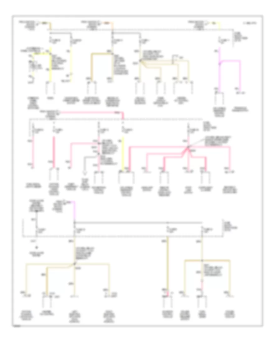
Power Distribution Wiring Diagram (2 of 4) for Oldsmobile Cutlass Supreme SL 1997
 https://portal-diagnostov.com/license.html
Automotive Electricians Portal FZCO
Automotive Electricians Portal FZCO
https://portal-diagnostov.com/license.html
https://portal-diagnostov.com/license.html
Automotive Electricians Portal FZCO
Automotive Electricians Portal FZCOList of elements for Power Distribution Wiring Diagram (2 of 4) for Oldsmobile Cutlass Supreme SL 1997:
- (c67)
- (cj2)
- (diagram 1 of 4)
- (i/p harn, behind right side of driver knee bolster, 3 cm from dlc breakout)
- (i/p harn, below i/p compt, 10 cm from vacuum/ electric sol breakout)
- (i/p harn, below i/p compt, 11 cm from blower motor relay breakout)
- (i/p harn, below i/p compt, 4 cm from 36-pin black connector)
- 1995 vftc c
- Abs relay (underhood electrical center #2)
- C10
- C67
- Cruise control module
- Cruise control release switch
- Daytime running lamps control module
- Daytime running lights (drl) module
- Door locks system
- Door locks system (seat belt/ ignition key/ lamls alarm)
- Electronic brake control module (ebcm)
- From ignition switch (diagram 1 of 4)
- From ignition switch b
- From ignition switch c
- From ignition switch d
- From ignition switch f
- Fuse 11 5a
- Fuse 12 10a
- Fuse 13 5a
- Fuse 15 15a
- Fuse 21 15a
- Fuse 24 15a
- Fuse 29 25a
- Fuse 3 10a
- Fuse 30 10a
- Fuse 38 10a
- Fuse 39 10a
- Fuse 4 15a
- Fuse 6 20a
- Fuse 7 20a
- Fuse block (right side of i/p)
- Headlamp switch
- Heater- a/c control
- Heater- a/c control (c67)
- Inflatable restraint control module
- Instrument cluster
- Left electric actuator (dual zone a/c)
- Nca
- Pnk
- Pnk a
- Pnk a4
- Pnk b
- Pnk f
- Powertrain control module
- Radio
- Rear window defog relay (cj2)
- Remote control door lock receiver
- Right electric actuator (dual zone a/c)
- S142 (eng harn, 11 cm from pcm breakout)
- S206
- S209
- S233
- S240 (i/p harn, left side of i/p bulkhead, 4 cm from 23-pin black connector)
- S243
- S247 (i/p harn, below i/p compt, 3 cm from i/p compt lamp breakout)
- Seat belt/ ignition key/ lamps alarm
- Sir coil
- Steering wheel radio control switches
- Stop lamp switch
- Sunroof control module
- Theft deterrent module
- To ign syst relay (diagram 1 of 4)
- Transaxle range switch
- Turn signal lamp flasher
- Turn signal lever
- Vacuum/ electric solenoid
- W/ steering wheel controls only
- Windshield wiper/washer switch
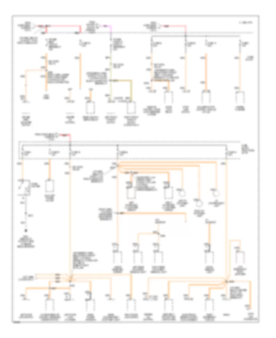
Power Distribution Wiring Diagram (3 of 4) for Oldsmobile Cutlass Supreme SL 1997
 https://portal-diagnostov.com/license.html
Automotive Electricians Portal FZCO
Automotive Electricians Portal FZCO
https://portal-diagnostov.com/license.html
https://portal-diagnostov.com/license.html
Automotive Electricians Portal FZCO
Automotive Electricians Portal FZCOList of elements for Power Distribution Wiring Diagram (3 of 4) for Oldsmobile Cutlass Supreme SL 1997:
- (2 door)
- (4 door)
- (c67) (cj2)
- (crossbody harn, below right front seat, 13 cm from breakout to ground at right 'b' pillar)
- (crossbody harn, below right front seat, 7 cm from breakout to ground bolted at base of right 'b' pillar)
- (crossbody harn, in right 'a' pillar, 7 cm from 23-pin black connector breakout)
- (diagram 1 of 4)
- (i/p harn, below center of i/p, 4 cm from radio breakout)
- (i/p harn, below i/p compt, 19 cm from fuse block)
- (i/p harn, below i/p compt, 4 cm from fuse block breakout)
- (not used)
- (roof harn, 4 cm from inside rear view mirror breakout)
- (sunshade illum mirror harn, in right 'a' pillar, 4 cm from sunshade illum mirror breakout)
- 1 fo 4)
- 1 of 4)
- 1995 vftc c
- Auxiliary power outlet
- B/h conn pin 3p
- B/h conn pin 4p
- B/h conn pin 5d
- B/h conn pin 7h
- B12 c1
- Block
- Blower motor control module (w/ cj2)
- C12
- C67
- Cigar lighter
- Cj2
- Data link connector
- Dome/ reading light
- Door lock relay
- Driver seat adjuster switch
- Electronic brake control module (ebcm)
- From ignition switch h
- From maxifuse #1 (diagram j
- From maxifuse #4 (diagram k
- From maxifuse #4 (diagram l
- Fuse
- Fuse 1 15a
- Fuse 10 15a
- Fuse 14 20a
- Fuse 16 30a
- Fuse 19 10a
- Fuse 23 15a
- Fuse 28 15a
- Fuse 32 20a
- Fuse 37 15a
- Fuse 5 15a
- Fuse block (right side of i/p)
- G g
- G201 (behind i/p, on right side of brake pedal bracket)
- Hazard flasher
- Heater a/c control
- Heater- a/c control
- I/p compartment lamp
- Inside rearview mirror
- Left door lock cylinder
- Left door lock switch
- Left front window switch
- Left i/p courtesy lamp
- Left rear courtesy/ reading light
- Left sunshade illuminated mirror
- Low frequency audio amplifier
- Nca
- Not used (4 door only)
- Outside remote control rearview mirror switch
- Power seat circuit breaker d 30a
- Power window circuit breaker c 20a
- Radio
- Radio power antenna
- Rear compartment courtesy light
- Rear window defog relay
- Red
- Remote control door lock receiver (w/ rke)
- Right door lock switch
- Right front window switch (2 door only)
- Right i/p courtesy lamp
- Right rear courtesy/ reading light
- Right sunshade illuminated mirror
- S201
- S202
- S213
- S216 red
- S306
- S308
- S318
- S380
- S391
- S395
- S501
- Seat belt/ ignition key/ lamps alarm
- Stop lamp switch
- Theft deterrent module
- W/ sunroof
- W/o sunroof
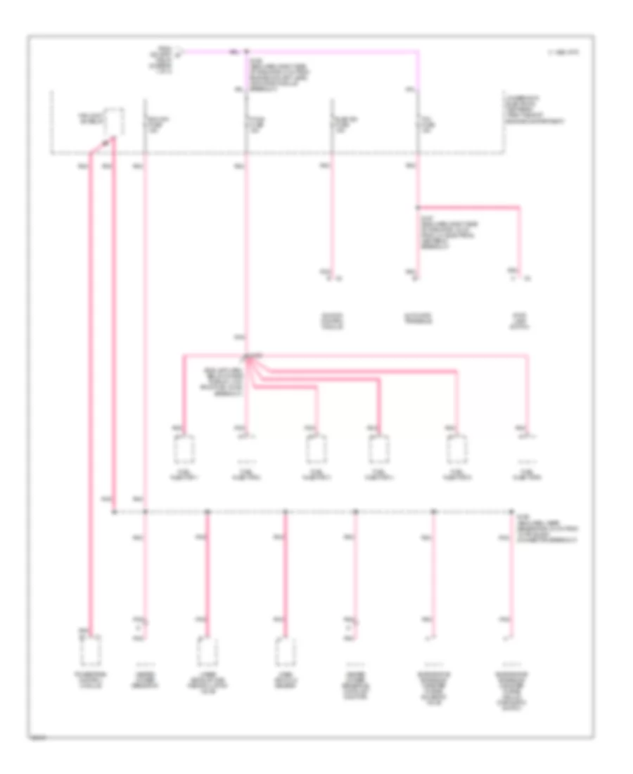
Power Distribution Wiring Diagram (4 of 4) for Oldsmobile Cutlass Supreme SL 1997
 https://portal-diagnostov.com/license.html
Automotive Electricians Portal FZCO
Automotive Electricians Portal FZCO
https://portal-diagnostov.com/license.html
https://portal-diagnostov.com/license.html
Automotive Electricians Portal FZCO
Automotive Electricians Portal FZCOList of elements for Power Distribution Wiring Diagram (4 of 4) for Oldsmobile Cutlass Supreme SL 1997:
- (eng jmp harn, below intake plenum, 2 cm from fuel inj #2 breakout)
- 1995 vftc c
- Automatic transaxle
- Ecm ign fuse 15a
- Elek ign fuse 15a
- Evaporative emissions canister purge solenoid valve
- Evaporative emissions canister purge vacuum diagnostic switch
- F/injn fuse 15a
- Fan cont #2 relay
- From ign syst e relay (diagram 1 of 4)
- Fuel injector 1
- Fuel injector 2
- Fuel injector 3
- Fuel injector 4
- Fuel injector 5
- Fuel injector 6
- Heated oxygen sensor #1
- Heated oxygen sensor #2 (catalyst monitor)
- Ignition control module
- Linear exhaust gas recirculation valve
- Mass air flow sensor
- Pnk
- Powertrain control module
- S109
- S156 (eng harn, near generator, 34 cm from 10-pin black connector breakout)
- S157 (eng harn, right side of radiator, 16 cm from u/h electrical center #1 breakout)
- Stop lamp switch
- Tcc fuse 15a
- Underhood electrical center #1 (right side of engine compartment)

 Čeština
 Dansk
Dansk Deutsch
 Ελληνικά
 English
 English
 Español
 Suomi
Suomi Français
 Français
 עברית
עברית Hrvatski
 Magyar
 Italiano
 日本語
日本語 Nederlands
 Polski
 Português
 Português
 Română
 Русский
 Slovenčina
 Slovenščina
 Svenska
 Türkçe
 中文 (中国)
