CRUISE CONTROL
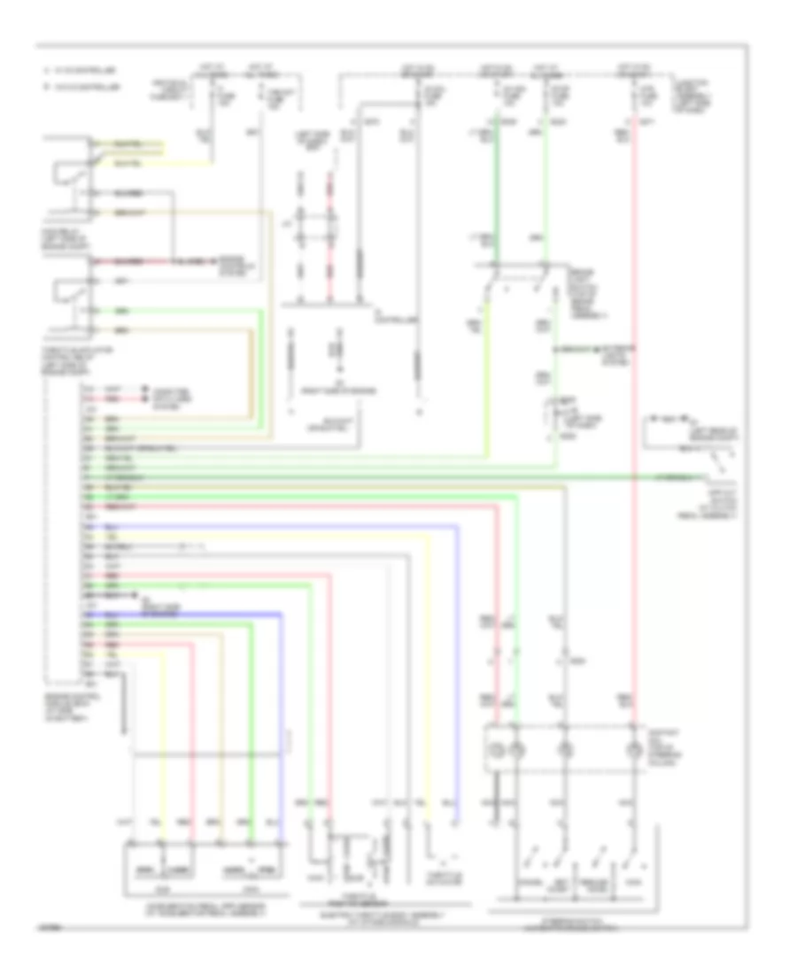
Cruise Control Wiring Diagram for Suzuki SX4 LE 2010
List of elements for Cruise Control Wiring Diagram for Suzuki SX4 LE 2010:
- (left side of dash)
- Acceleration pedal (app) sensor (at accelerator pedal assembly)
- Bcm
- Brake light switch (top of brake pedal assembly)
- C01
- Cancel
- Close
- Computer data lines system
- Contact coil (top of steering column)
- Cpp cut switch (at clutch pedal assembly)
- E01
- E323
- E325
- E383
- Electric throttle body assembly (at intake manifold)
- Engine control module (ecm) (at side of battery)
- Engine controls system
- Exterior lights system
- Fi fuse 15a
- G271
- G272
- G3 (right side of engine)
- G7 (left rear of engine compt)
- Hot at all times
- Hot in on or start
- Id controller
- Ig coil fuse 15a
- Ig1 sig fuse 10a
- Individual circuit fuse box 1
- J/b (left side of dash)
- J/c
- Junction block assembly (left side of dash)
- Main
- Main relay (left side of engine compt)
- Mtr fuse 10a
- Nca
- Open
- Red
- Resume/ accel
- Set/ coast
- Steering switch (automatic cruise switch)
- Stop fuse 10a
- Sub
- Thr mot fuse 15a
- Throttle actuator
- Throttle actuator control relay (left side of engine compt)
- Throttle position sensor
- W/ id controller
- W/o id controller
 Čeština
 Dansk
Dansk Deutsch
 Ελληνικά
 English
 English
 Español
 Suomi
Suomi Français
 Français
 עברית
עברית Hrvatski
 Magyar
 Italiano
 日本語
日本語 Nederlands
 Polski
 Português
 Português
 Română
 Русский
 Slovenčina
 Slovenščina
 Svenska
 Türkçe
 中文 (中国)
 한국어
한국어