ПРЕДУПРЕЖДАЮЩИЕ СИСТЕМЫ
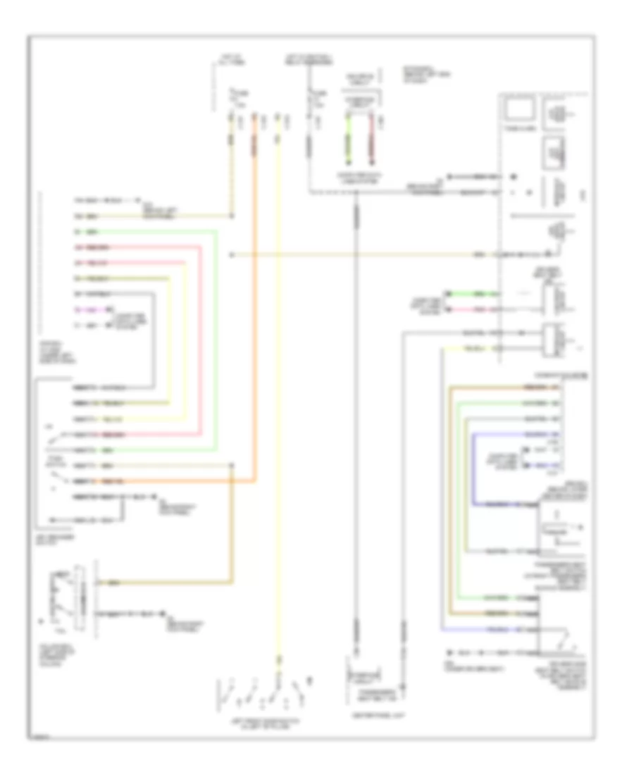
Электросхема сигнала, эволюция для Mitsubishi Lancer Evolution GSR 2008
 https://portal-diagnostov.com/license.html
Automotive Electricians Portal FZCO
Automotive Electricians Portal FZCO
https://portal-diagnostov.com/license.html
https://portal-diagnostov.com/license.html
Automotive Electricians Portal FZCO
Automotive Electricians Portal FZCO
Электросхема сигнала, эволюция для Mitsubishi Lancer Evolution GSR 2008 - Список элементов:
- (each lcd
- (key reminder)
- C-301
- C-313
- C-315
- C-317
- C-36
- C-37
- Can drive circuit
- Center panel unit
- Circuit can drive
- Circuit interface
- Column ecu
- Column ecu (left side of steering column)
- Combination meter
- Computer data lines system
- Cpu
- Door)
- Drive circuit
- Driver's seat belt ind
- Driver's side seat belt switch (in driver's seat belt buckle assembly)
- Etacs-ecu (behind left end of dash)
- Fuse 7.5a
- G18 (behind left kick panel)
- G20 (under driver's seat)
- G4 (behind right kick panel)
- Hall ic
- Head
- Hot at all times
- Hot w/ ignition 1 relay energized
- Interface circuit
- Key reminder switch
- Kos ecu (w/ kos) (under left side of dash)
- Lcd
- Led
- Left front door switch (in left "b" pillar)
- Lighting switch
- Nca
- Passenger's seat belt ind
- Passenger's seat belt switch (in front passenger's seat belt buckle assembly)
- Pnk
- Push switch
- Srs ecu (behind lower center of dash)
- Tail
- Tone alarm
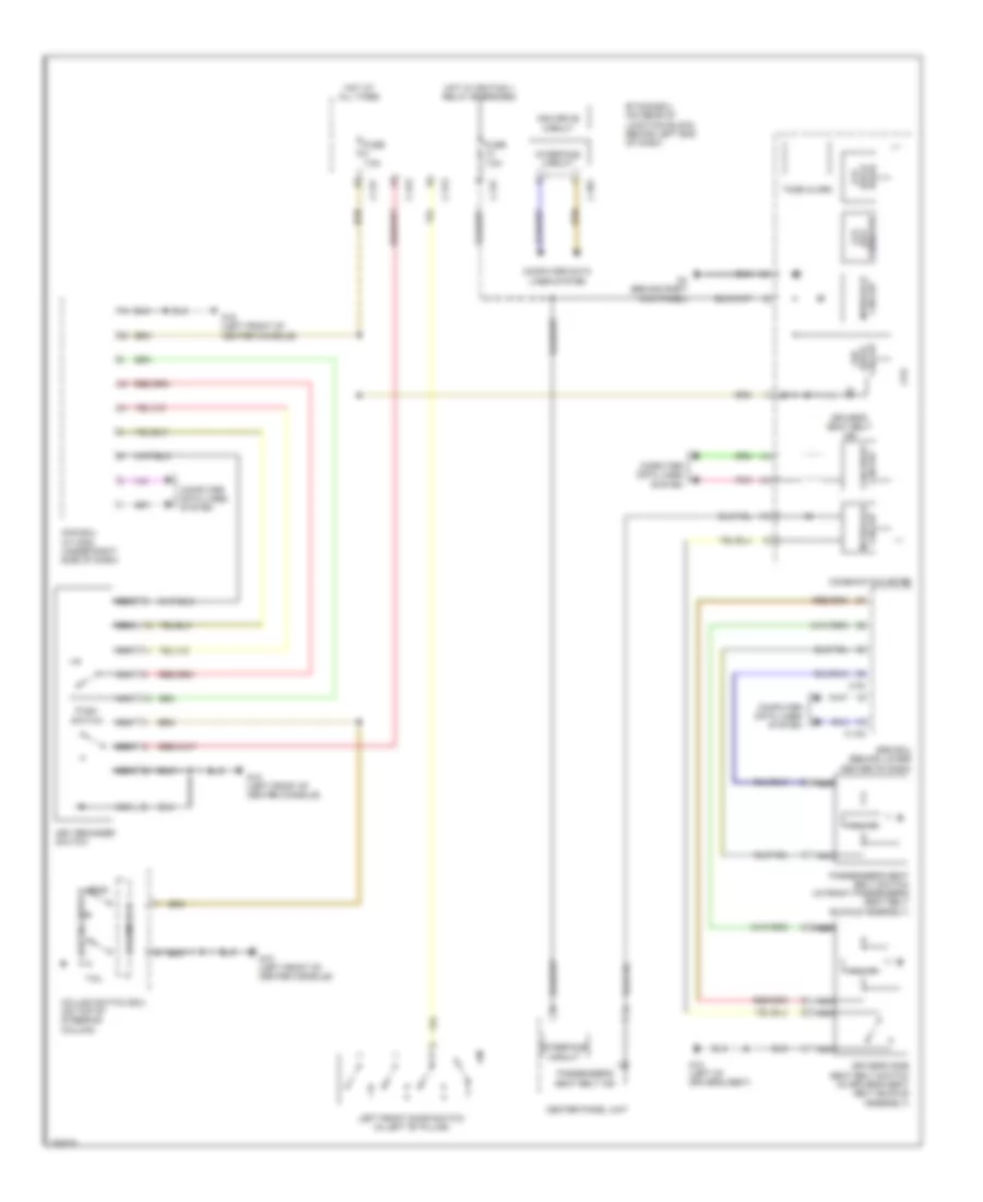
Электросхема сигнала, кроме эволюции для Mitsubishi Lancer Evolution GSR 2008
 https://portal-diagnostov.com/license.html
Automotive Electricians Portal FZCO
Automotive Electricians Portal FZCO
https://portal-diagnostov.com/license.html
https://portal-diagnostov.com/license.html
Automotive Electricians Portal FZCO
Automotive Electricians Portal FZCOЭлектросхема сигнала, кроме эволюции для Mitsubishi Lancer Evolution GSR 2008 - Список элементов:
- (each lcd
- C-122
- C-30
- C-301
- C-313
- C-315
- C-317
- Can drive circuit
- Center panel unit
- Circuit can drive
- Circuit interface
- Column ecu
- Column switch ecu (on top of steering column)
- Combination meter
- Computer data lines system
- Cpu
- Door)
- Drive circuit
- Driver's seat belt ind
- Driver's side seat belt switch (in driver's seat belt buckle assembly)
- Etacs-ecu (on rear of junction block, behind left end of dash)
- Fuse 7.5a
- G12 (left of driver's seat)
- G15 (left front of center console)
- G4 (behind right kick panel)
- Hall ic
- Head
- Hot at all times
- Hot w/ ignition 1 relay energized
- Interface circuit
- Key reminder switch
- Kos ecu (w/ kos) (under right side of dash)
- Led
- Left front door switch (in left "b" pillar)
- Lighting switch
- Nca
- Passenger's seat belt ind
- Passenger's seat belt switch (in front passenger's seat belt buckle assembly)
- Pnk
- Push switch
- Reminder) (key lcd
- Srs ecu (behind lower center of dash)
- Tail
- Tone alarm
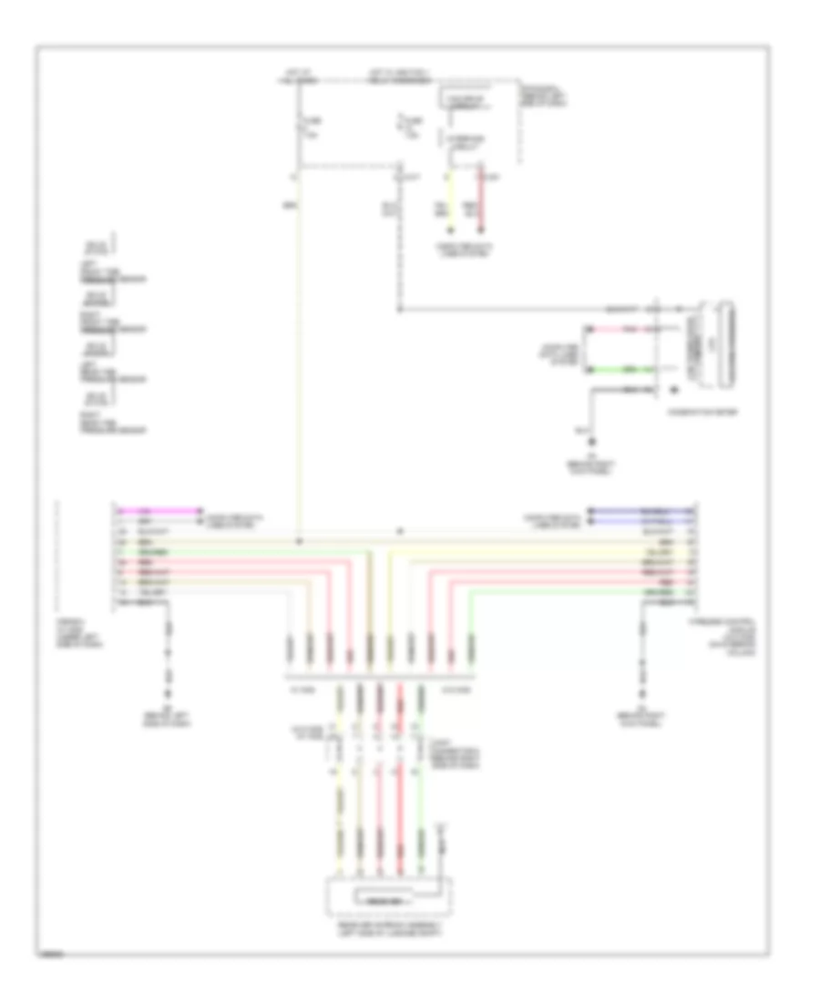
Электросхема системы контроля давления в шинах, эволюция для Mitsubishi Lancer Evolution GSR 2008
 https://portal-diagnostov.com/license.html
Automotive Electricians Portal FZCO
Automotive Electricians Portal FZCO
https://portal-diagnostov.com/license.html
https://portal-diagnostov.com/license.html
Automotive Electricians Portal FZCO
Automotive Electricians Portal FZCOЭлектросхема системы контроля давления в шинах, эволюция для Mitsubishi Lancer Evolution GSR 2008 - Список элементов:
- (w/o kos) (w/ kos)
- C-301
- C-317
- Can drive circuit
- Can transceiver
- Circuit
- Combination meter
- Computer data lines system
- Cpu
- Etacs-ecu (behind left end of dash)
- Fuse 7.5a
- G4 (behind right kick panel)
- G6 (behind left side of dash)
- Hot at all times
- Hot w/ ignition 1 relay energized
- Interface circuit
- Joint connector 6 (behind right side of dash)
- Kos-ecu (w/ kos) (under left side of dash)
- Lcd (tire pressure)
- Left front tire pressure sensor
- Left rear tire pressure sensor
- Nca
- Pnk
- Receiver
- Receiver antenna assembly (left side of luggage compt)
- Red
- Right front tire pressure sensor
- Right rear tire pressure sensor
- Solid state
- W/ kos
- W/o kos
- Wireless control module (w/o kos) (on steering column)
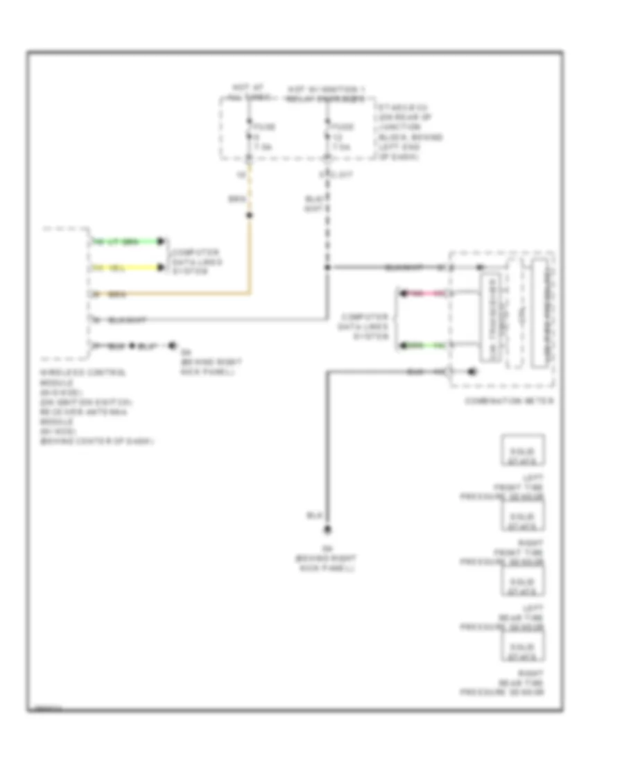
Электросхема системы контроля давления в шинах, кроме эволюции для Mitsubishi Lancer Evolution GSR 2008
 https://portal-diagnostov.com/license.html
Automotive Electricians Portal FZCO
Automotive Electricians Portal FZCO
https://portal-diagnostov.com/license.html
https://portal-diagnostov.com/license.html
Automotive Electricians Portal FZCO
Automotive Electricians Portal FZCOЭлектросхема системы контроля давления в шинах, кроме эволюции для Mitsubishi Lancer Evolution GSR 2008 - Список элементов:
- C-317
- Can transceiver
- Circuit
- Combination meter
- Computer data lines system
- Cpu
- Etasc-ecu (on rear of junction block, behind left end of dash)
- Fuse 7.5a
- G4 (behind right kick panel)
- Hot at all times
- Hot w/ ignition 1 relay energized
- Lcd (tire pressure)
- Left front tire pressure sensor
- Left rear tire pressure sensor
- Pnk
- Right front tire pressure sensor
- Right rear tire pressure sensor
- Solid state
- Wireless control module (w/o kos) (on ignition switch) receiver antenna module (w/ kos) (behind center of dash)

 Čeština
 Dansk
Dansk Deutsch
 Ελληνικά
 English
 English
 Español
 Suomi
Suomi Français
 Français
 עברית
עברית Hrvatski
 Magyar
 Italiano
 日本語
日本語 Nederlands
 Polski
 Português
 Português
 Română
 Русский
 Slovenčina
 Slovenščina
 Svenska
 Türkçe
 中文 (中国)
