СИСТЕМА УПРАВЛЕНИЯ ДВИГАТЕЛЯ
1.5L
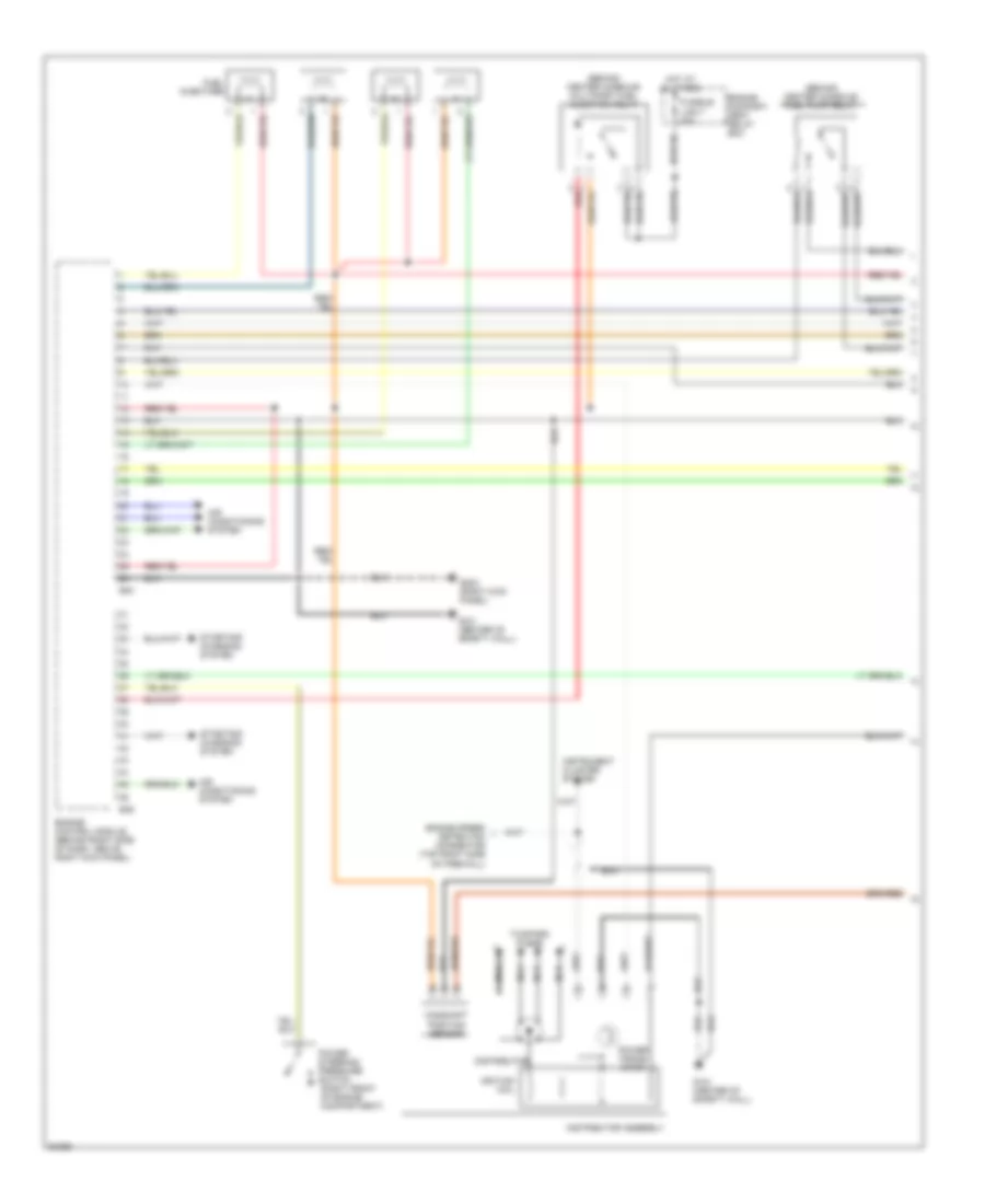
1.5L, Электросхема системы управления двигателя (1 из 3) для Mitsubishi Mirage DE 1997
 https://portal-diagnostov.com/license.html
Automotive Electricians Portal FZCO
Automotive Electricians Portal FZCO
https://portal-diagnostov.com/license.html
https://portal-diagnostov.com/license.html
Automotive Electricians Portal FZCO
Automotive Electricians Portal FZCO
1.5L, Электросхема системы управления двигателя (1 из 3) для Mitsubishi Mirage DE 1997 - Список элементов:
- (behind center console) fuel pump relay
- (behind center console) multiport fuel injection relay
- (right front of engine compartment)
- Air conditioning system
- B39
- B40
- Camshaft position sensor
- Distributor
- Distributor assembly
- Engine compart- ment relay box
- Engine control module (behind right side of dash, above right kick panel)
- Engine speed detection connector (top right side of firewall)
- Fuel injectors
- Fusible link 7 20a
- G121 (center of safety wall)
- G203 (right kick panel)
- Hot at all times
- Ignition coil
- Instrument cluster system
- Nca
- Power
- Power trans- istor
- Red
- Starting/ charging system
- Steering pressure
- Switch
- To spark plugs
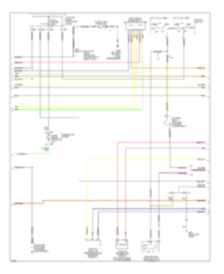
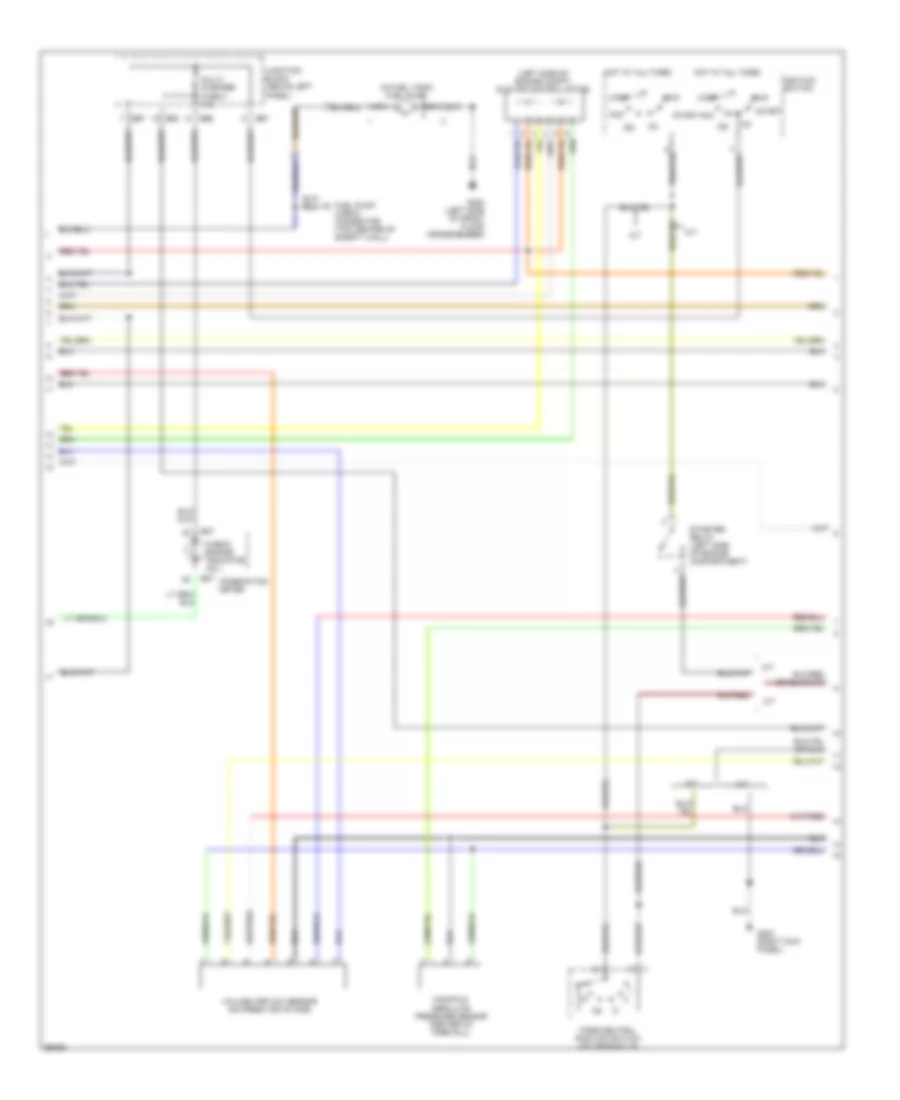
1.5L, Электросхема системы управления двигателя (2 из 3) для Mitsubishi Mirage DE 1997
 https://portal-diagnostov.com/license.html
Automotive Electricians Portal FZCO
Automotive Electricians Portal FZCO
https://portal-diagnostov.com/license.html
https://portal-diagnostov.com/license.html
Automotive Electricians Portal FZCO
Automotive Electricians Portal FZCO1.5L, Электросхема системы управления двигателя (2 из 3) для Mitsubishi Mirage DE 1997 - Список элементов:
- (in fuel tank) fuel pump
- (left side of engine compt) idle air control motor
- A/t
- Acc
- B07
- B63
- B66
- B67
- Capacitor (left side of engine compartment)
- Check connector (top center of safety wall)
- Check engine indicator (mil)
- Combination meter
- Fuel pump
- G203 (right kick panel)
- G300 (left side of front floor crossmember)
- Hot at all times
- Ig1
- Ig2
- Ignition switch
- Intake air temperature sensor (on intake plenum, on top of engine)
- Junction block (above left panel)
- Lock
- M/t
- Manifold absolute pressure sensor (center of firewall)
- Multi- purpose fuse 4 10a
- Nca
- Park/neutral position switch (on transaxle)
- Run
- Start
- Starter relay (left side of engine compartment)
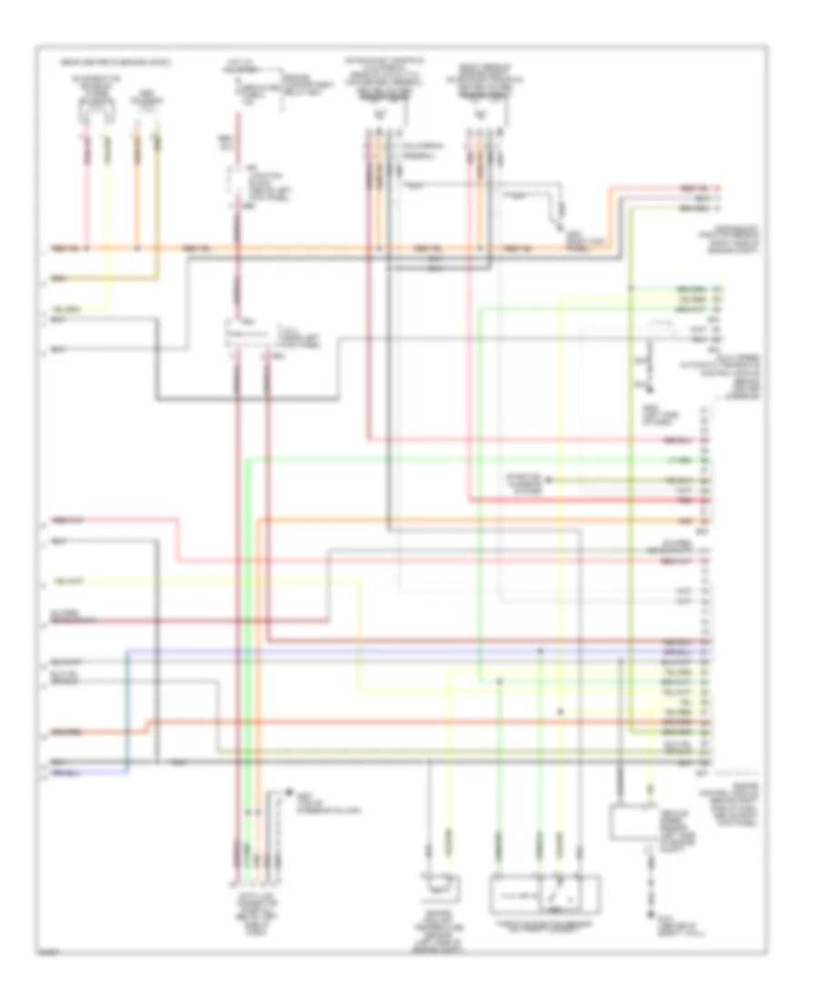
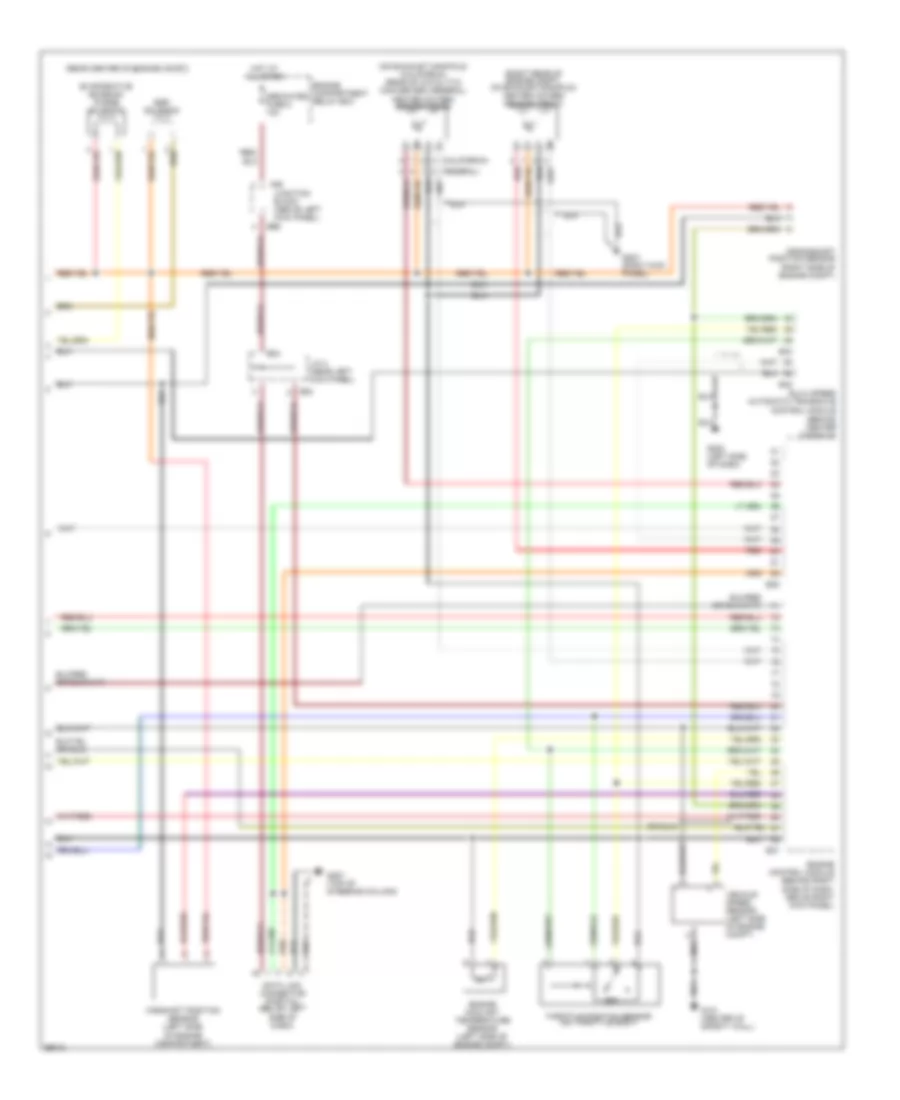
1.5L, Электросхема системы управления двигателя (3 из 3) для Mitsubishi Mirage DE 1997
 https://portal-diagnostov.com/license.html
Automotive Electricians Portal FZCO
Automotive Electricians Portal FZCO
https://portal-diagnostov.com/license.html
https://portal-diagnostov.com/license.html
Automotive Electricians Portal FZCO
Automotive Electricians Portal FZCO1.5L, Электросхема системы управления двигателя (3 из 3) для Mitsubishi Mirage DE 1997 - Список элементов:
- (california)
- (on exhaust manifold) (california) (rear of catalytic converter) (federal) heated oxygen sensor (rear)
- (rear center of engine compt)
- (right rear of engine compt, on exhaust manifold) heated oxygen sensor (front)
- B24
- B37
- B38
- B42
- B43
- B66
- C60
- Crankshaft position sensor (right side of engine compt)
- Data link connector (partial) (below left
- Dedicated fuse 2 10a
- Egr solenoid
- Elc-4 speed automatic transaxle control module (behind center console)
- Engine compartment relay box
- Engine control module (behind right side of dash, above right kick panel)
- Engine coolant temperature sensor (left side of engine compt)
- Evaporative emission purge solenoid
- G121 (center of safety wall)
- G202 (left side of dash)
- G203 (right kick panel)
- G207 (top of steering column)
- Hot at all times
- J/c 3 (near left kick panel)
- Junction block (above left kick panel)
- Red
- Side of dash)
- Starting/ charging system
- Throttle position sensor (on throttle body)
- Vehicle speed sensor (left side of engine compt)
1.8L
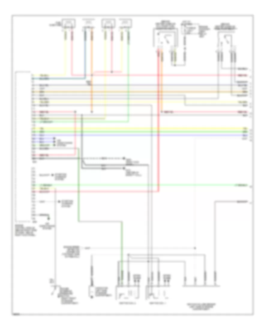
1.8L, Электросхема системы управления двигателя (1 из 3) для Mitsubishi Mirage DE 1997
 https://portal-diagnostov.com/license.html
Automotive Electricians Portal FZCO
Automotive Electricians Portal FZCO
https://portal-diagnostov.com/license.html
https://portal-diagnostov.com/license.html
Automotive Electricians Portal FZCO
Automotive Electricians Portal FZCO1.8L, Электросхема системы управления двигателя (1 из 3) для Mitsubishi Mirage DE 1997 - Список элементов:
- (behind center console) fuel pump relay
- (behind center console) multiport fuel injection relay
- (right front of engine compartment)
- Air conditioning system
- B39
- B40
- Capacitor (left side of engine compartment)
- Engine compart- ment relay box
- Engine control module (behind right side of dash, above right kick panel)
- Engine speed detection connector (top right side of firewall)
- Fuel injectors
- Fusible link 7 20a
- G121 (center of safety wall)
- G203 (right kick panel)
- Hot at all times
- Ignition coil 1
- Ignition coil 2
- Ignition failure sensor (left side of engine compartment)
- Nca
- Power
- Red
- Spark plugs
- Starting/ charging system
- Steering pressure
- Switch
1.8L, Электросхема системы управления двигателя (2 из 3) для Mitsubishi Mirage DE 1997
 https://portal-diagnostov.com/license.html
Automotive Electricians Portal FZCO
Automotive Electricians Portal FZCO
https://portal-diagnostov.com/license.html
https://portal-diagnostov.com/license.html
Automotive Electricians Portal FZCO
Automotive Electricians Portal FZCO1.8L, Электросхема системы управления двигателя (2 из 3) для Mitsubishi Mirage DE 1997 - Список элементов:
- (in fuel tank) fuel pump
- (left side of engine compt) idle air control motor
- A/t
- Acc
- B07
- B63
- B66
- B67
- Check connector (top center of safety wall)
- Check engine indicator (mil)
- Combination meter
- Fuel pump
- G203 (right kick panel)
- G300 (left side of front floor crossmember)
- Hot at all times
- Ig1
- Ig2
- Ignition switch
- Junction block (above left panel)
- Lock
- M/t
- Manifold absolute pressure sensor (center of firewall)
- Multi- purpose fuse 4 10a
- Nca
- Park/neutral position switch (on transaxle)
- Run
- Start
- Starter relay (left side of engine compartment)
- Volume airflow sensor (on fresh air intake)
1.8L, Электросхема системы управления двигателя (3 из 3) для Mitsubishi Mirage DE 1997
 https://portal-diagnostov.com/license.html
Automotive Electricians Portal FZCO
Automotive Electricians Portal FZCO
https://portal-diagnostov.com/license.html
https://portal-diagnostov.com/license.html
Automotive Electricians Portal FZCO
Automotive Electricians Portal FZCO1.8L, Электросхема системы управления двигателя (3 из 3) для Mitsubishi Mirage DE 1997 - Список элементов:
- (california)
- (on exhaust manifold) (california) (rear of catalytic converter) (federal) heated oxygen sensor (rear)
- (rear center of engine compt)
- (right rear of engine compt, on exhaust manifold) heated oxygen sensor (front)
- B24
- B37
- B38
- B42
- B43
- B66
- C60
- Camshaft position sensor (left side of engine compartment)
- Crankshaft position sensor (right side of engine compt)
- Data link connector (partial) (below left
- Dedicated fuse 2 10a
- Egr solenoid
- Elc-4 speed automatic transaxle control module (behind center console)
- Engine compartment relay box
- Engine control module (behind right side of dash, above right kick panel)
- Engine coolant temperature sensor (left side of engine compt)
- Evaporative emission purge solenoid
- G121 (center of safety wall)
- G202 (left side of dash)
- G203 (right kick panel)
- G207 (top of steering column)
- Hot at all times
- J/c 3 (near left kick panel)
- Junction block (above left kick panel)
- Red
- Side of dash)
- Throttle position sensor (on throttle body)
- Vehicle speed sensor (left side of engine compt)

 Čeština
 Dansk
Dansk Deutsch
 Ελληνικά
 English
 English
 Español
 Suomi
Suomi Français
 Français
 עברית
עברית Hrvatski
 Magyar
 Italiano
 日本語
日本語 Nederlands
 Polski
 Português
 Português
 Română
 Русский
 Slovenčina
 Slovenščina
 Svenska
 Türkçe
 中文 (中国)
