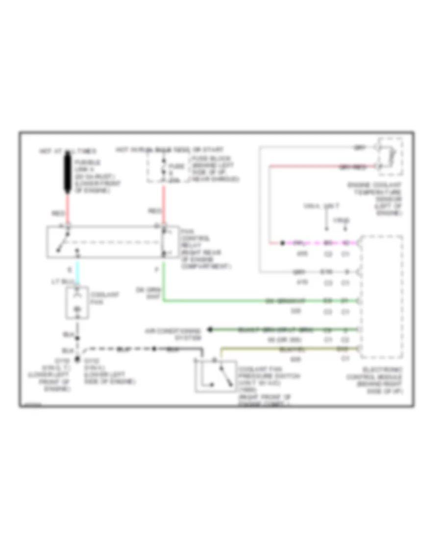
COOLING FAN
Cooling Fan Wiring Diagram for Chevrolet Beretta GT 1990
 https://portal-diagnostov.com/license.html
Automotive Electricians Portal FZCO
Automotive Electricians Portal FZCO
https://portal-diagnostov.com/license.html
https://portal-diagnostov.com/license.html
Automotive Electricians Portal FZCO
Automotive Electricians Portal FZCO
List of elements for Cooling Fan Wiring Diagram for Chevrolet Beretta GT 1990:
- 66 (or 366)
- Air conditioning system
- Coolant fan
- Coolant fan pressure switch (vin t w/ a/c) (1990) (right front of engine compt.)
- D12
- E16
- Electronic control module (behind right side of i/p)
- Engine coolant temperature sensor (left of engine)
- Fan control relay (right rear of engine compartment)
- Fuse 20a
- Fuse block (behind left side of i/p, near shroud)
- Fusible link a (20 ga-rust) (lower front of engine)
- G110 (vin g, t) (lower left front of engine)
- G112 (vin a) (lower left side of engine)
- Hot at all times
- Hot in run, bulb test or start
- Red
- Vin a, vin t
- Vin g
 Čeština
 Dansk
Dansk Deutsch
 Ελληνικά
 English
 English
 Español
 Suomi
Suomi Français
 Français
 עברית
עברית Hrvatski
 Magyar
 Italiano
 日本語
日本語 Nederlands
 Polski
 Português
 Português
 Română
 Русский
 Slovenčina
 Slovenščina
 Svenska
 Türkçe
 中文 (中国)
 한국어
한국어
