POWER DISTRIBUTION
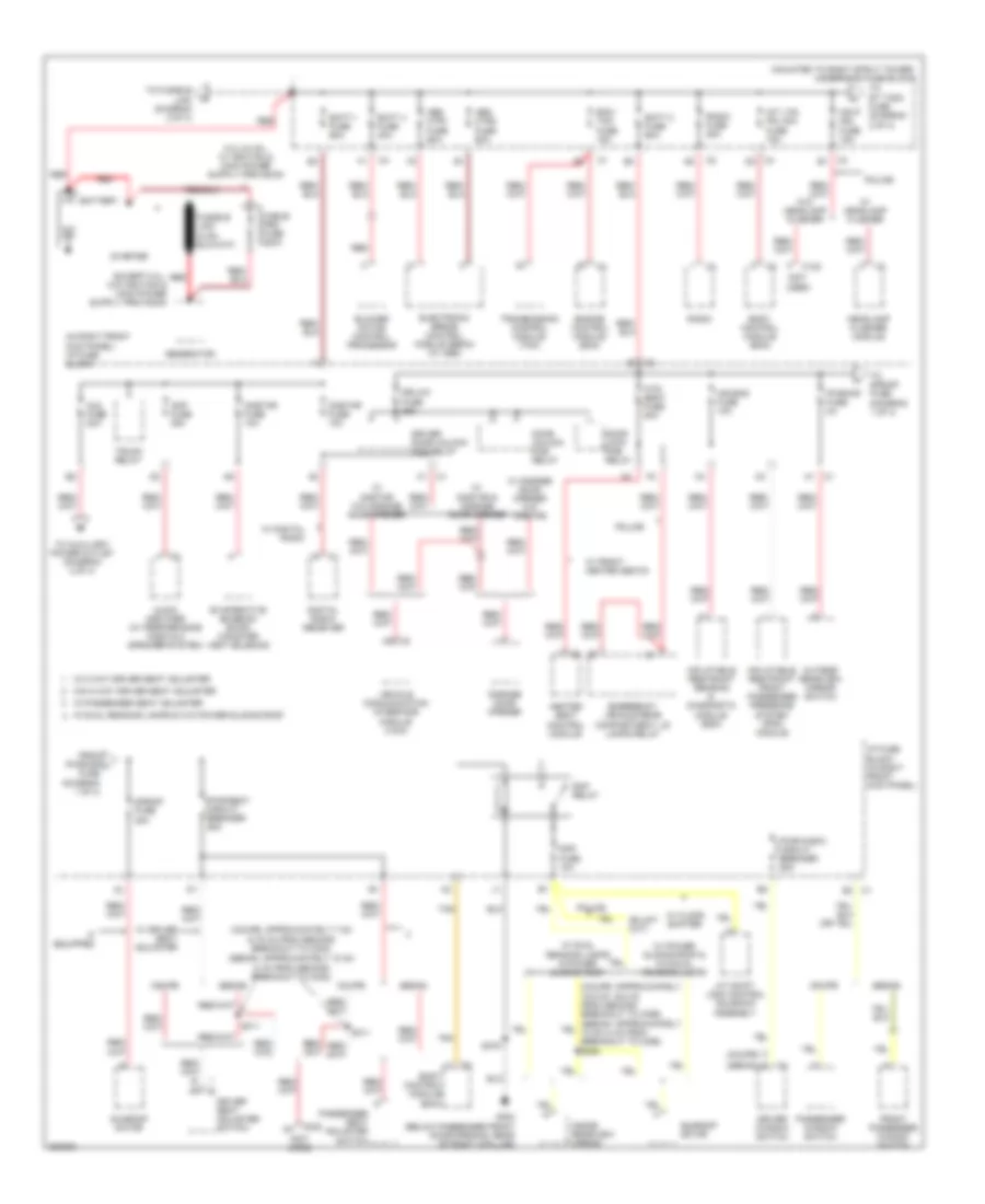
Power Distribution Wiring Diagram (1 of 4) for Chevrolet Monte Carlo SS 2006
 https://portal-diagnostov.com/license.html
Automotive Electricians Portal FZCO
Automotive Electricians Portal FZCO
https://portal-diagnostov.com/license.html
https://portal-diagnostov.com/license.html
Automotive Electricians Portal FZCO
Automotive Electricians Portal FZCO
List of elements for Power Distribution Wiring Diagram (1 of 4) for Chevrolet Monte Carlo SS 2006:
- (2.75 in) from second breakout to c302) (sedan: approximately 10 cm
- (4 in) from second breakout to c302)
- (coupe: approximately 7 cm
- (in right front kick panel) i/p fuse block
- (mounted to right strut tower) underhood fuse block
- (not used)
- A/t shift lock control solenoid assembly
- Abs mtr1 fuse 60a
- Abs mtr2 fuse 60a
- Air bag fuse 10a
- Amp fuse 25a
- Audio amplifier (w/ performance audio & 8 speaker system)
- Aux fuse 20a
- B3 c1
- Batt 1 fuse 60a
- Batt 2 fuse 60a
- Batt 4 fuse 30a
- Battery
- Blower motor control processor
- Body control module (bcm)
- C (coupe)
- C1 c1
- C122
- C3 b1
- C302
- C4 d2
- Cable pro fuse 200a
- Cnstar fuse 10a
- Coupe
- Digital radio receiver
- Door lock pcb relay
- Door unlock pcb relay
- Dr/lck fuse 25a
- Driver door unlock pcb relay
- Driver seat adjuster switch
- Driver window switch
- E (sedan)
- Ecm/ tcm fuse 15a
- Electronic brake control module (ebcm) (w/ abs)
- Emergency vehicle rear compartment lid lamps relay
- Engine control module (ecm)
- Evaporative emission (evap) canister vent solenoid
- From pwr/mir j fuse (diagram 1 of 4)
- Front passenger window switch
- G302 (below passenger front door opening, rear of right a-pillar)
- Garage door opener
- Generator
- Hdlp mdl fuse 15a
- Headlamp flasher module
- Heated seat control module
- Htd/ seat fuse 20a
- I/p fuse block (in right front kick panel)
- If equipped
- Inflatable restraint front passenger presence system (pps) module
- Inflatable restraint sensing & diagnostic module (sdm)
- Inside rearview mirror
- Int lts/ pnl dim fuse 15a
- Onstar fuse 10a
- Outside rearview mirror switch
- Passenger seat adjuster switch
- Passenger window switch
- Police
- Pwr/mir fuse 2a
- Pwr/seat circuit breaker 25a
- Pwr/wndw circuit breaker 25a
- Radio
- Radio fuse 20a
- Rap fuse 10a
- Rap relay
- Red
- S/roof fuse 20a
- S311
- S375
- Sedan
- Starter
- Sunroof motor
- Tan
- To auxiliary power outlet (diagram 2 0f 4)
- To fusible link (diagram 2 of 4)
- To rt t/sig fuse (diagram 2 of 4)
- To s/roof fuse (diagram 1 of 4)
- Transmission control module (tcm)
- Trunk relay
- Vehicle communication interface module (vcim)
- W/ 8 way driver seat adjuster
- W/ digital radio
- W/ driver seat adjuster
- W/ dual reading lamps & power sliding roof
- W/ dual reading lamps & w/o power sliding roof
- W/ floor shifter
- W/ front heated seats
- W/ garage door opener w/o onstar
- W/ headlamp flasher
- W/ onstar & garage door opener
- W/ onstar w/o garage door opener
- W/ passenger seat adjuster
- W/ power sliding roof & w/o dual reading lamps
- W/o 8 way driver seat adjuster
- W/o headlamp flasher
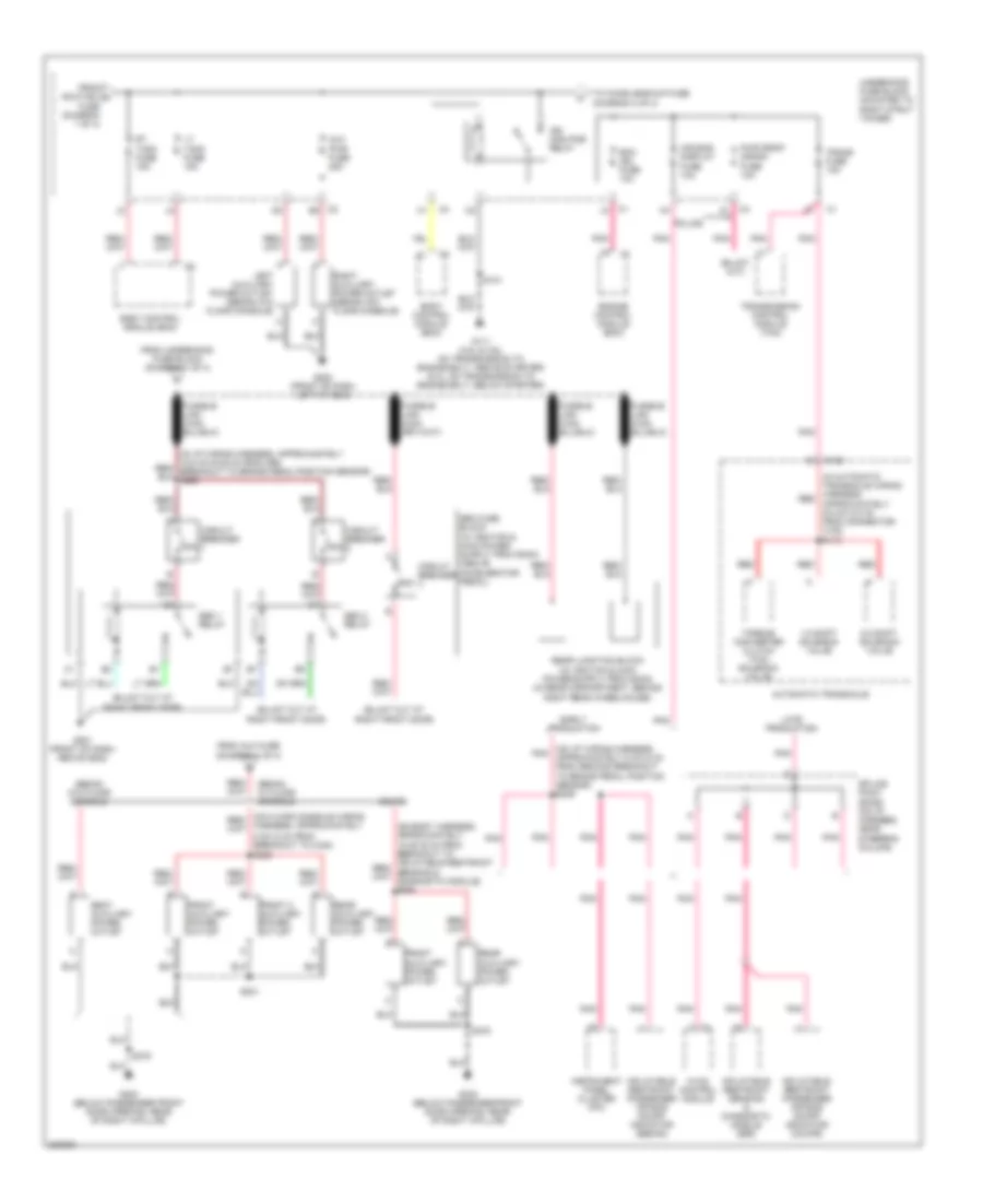
Power Distribution Wiring Diagram (2 of 4) for Chevrolet Monte Carlo SS 2006
 https://portal-diagnostov.com/license.html
Automotive Electricians Portal FZCO
Automotive Electricians Portal FZCO
https://portal-diagnostov.com/license.html
https://portal-diagnostov.com/license.html
Automotive Electricians Portal FZCO
Automotive Electricians Portal FZCOList of elements for Power Distribution Wiring Diagram (2 of 4) for Chevrolet Monte Carlo SS 2006:
- (in automatic transaxle wiring harness, red approximately 9.5 cm (3.8 in) from connector c100) s115
- (on i/p wiring harness, pnk approximately 5 cm (2 in) from second breakout to brake pedal position sensor) s239
- 1-2 shift solenoid valve
- 2-3 shift solenoid valve
- 30a
- 5 cm (2 in) from breakout to c340)
- 50a
- Air bag/ display fuse 10a
- Automatic transaxle
- Aux pwr fuse 25a
- Body control module (bcm)
- C1 j3
- C100
- C2 e2
- C4 k1
- Circuit breaker
- Coupe
- Early production
- Ecm ign fuse 10a
- Engine control module (ecm)
- From aux fuse (diagram 1 of 4)
- From hdlp mdl a fuse (diagram 1 of 4)
- From underhood fuse block (diagram 1 of 4)
- Front 2 auxiliary power outlet
- Front auxiliary power outlet
- G111 (3.5l & 3.9l: on transmission to engine bolt, above starter) (5.3l: on transmission to engine bolt, below starter)
- G200 (front of dash, left of g204)
- G201 (front of dash, above g202)
- G302 (below passenger front door opening, rear of right a-pillar)
- Harness, approximately
- Hvac control module
- Ign main pcb relay
- Inflatable restraint passenger air bag on/off indicator (coupe)
- Inflatable restraint passenger air bag on/off indicator (sedan)
- Inflatable restraint sensing & diagnostic module (sdm)
- Instrument panel cluster (ipc)
- Late production
- Left auxiliary power outlet (sedan w/o floor console)
- Lt t/sig fuse 15a
- Pnk
- Police
- Pwr drop/ crank fuse 10a
- Rear auxiliary power outlet
- Red
- Right auxiliary power outlet (sedan w/o floor console)
- Rt t/sig fuse 15a
- S101
- S231
- S238
- S375
- Seat auxiliary power outlet
- Sedan w/ floor console
- Sedan w/o floor console
- Seo 1 relay
- Seo 2 relay
- Splice pack sp206 (on i/p harness, near steering column)
- To chmsl/backup fuse (diagram 3 of 4)
- Torque converter clutch (tcc) solenoid valve
- Trans fuse 10a
- Transmission control module (tcm)
- Underhood fuse block (mounted to right strut tower)
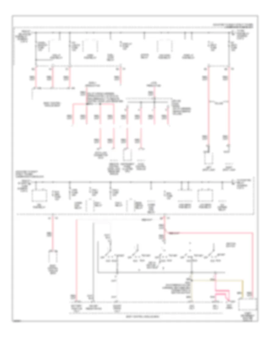
Power Distribution Wiring Diagram (3 of 4) for Chevrolet Monte Carlo SS 2006
 https://portal-diagnostov.com/license.html
Automotive Electricians Portal FZCO
Automotive Electricians Portal FZCO
https://portal-diagnostov.com/license.html
https://portal-diagnostov.com/license.html
Automotive Electricians Portal FZCO
Automotive Electricians Portal FZCOList of elements for Power Distribution Wiring Diagram (3 of 4) for Chevrolet Monte Carlo SS 2006:
- (mounted to right strut tower) underhood fuse block
- (not used)
- A/c cmprsr relay
- Acc
- Acc volt
- Battery positive volt
- Bcm fuse 10a
- Body control module (bcm)
- C201
- Chmsl/ backup fuse 10a
- Data link connector (dlc)
- Display fuse 10a
- Drl pcb relay
- Early production
- Fan 1 fuse 30a
- Fan 1 relay
- Fan 2 fuse 30a
- Fan 3 relay
- Fog lp pcb relay
- From ign main c pcb relay (diagram 2 of 4)
- From rt spot d fuse (diagram 3 of 4)
- Fuel/ pump relay
- High beam pcb relay
- Horn pcb relay
- Hvac control module
- Ign 1 volt
- Ign key resistor sig
- Ignition switch
- Instrument panel cluster (ipc)
- Int lights fuse 10a
- Key in ignition switch
- Late production
- Left spot lamp
- Low beam pcb relay
- Lt spot fuse 15a
- Nca
- Off
- On/off/ crank volt
- Park lp pcb relay
- Pnk
- Police
- Rear defog relay
- Remote control door lock receiver (rcdlr)
- Right spot lamp
- Rt spot fuse 15a
- Run
- Rvc sen fuse 10a
- S204 (on steering column harness, between bcm connector c1 & ignition switch)
- Splice pack sp206 (on i/p harness, near steering column)
- Start
- Strtr relay
- Theft deterrent exciter module
- To drl pcb relay (diagram 3 of 4)
- To pwr/trn relay (diagram 4 of 4)
- Wiper high pcb relay
- Wiper pcb relay
- Wpr fuse 25a
- Ws wash pcb relay
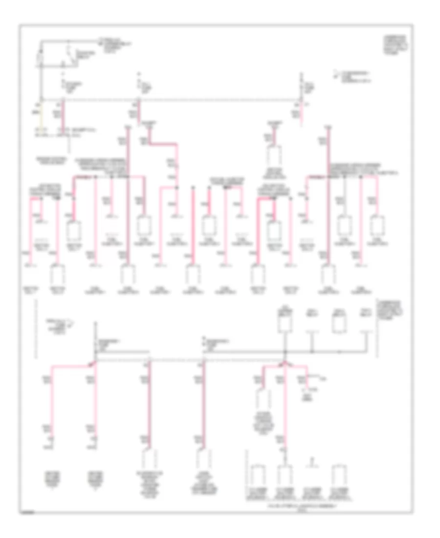
Power Distribution Wiring Diagram (4 of 4) for Chevrolet Monte Carlo SS 2006
 https://portal-diagnostov.com/license.html
Automotive Electricians Portal FZCO
Automotive Electricians Portal FZCO
https://portal-diagnostov.com/license.html
https://portal-diagnostov.com/license.html
Automotive Electricians Portal FZCO
Automotive Electricians Portal FZCOList of elements for Power Distribution Wiring Diagram (4 of 4) for Chevrolet Monte Carlo SS 2006:
- (5.3l)
- (except 5.3l)
- (in engine wiring harness, approximately 5 cm (2 in) from breakout to fuel injector 3) s108
- (in engine wiring harness, approximately 5 cm (2 in) from breakout to fuel injector 4) s109
- (not used)
- (on fuel injector wiring harness) s109
- (on ignition control module wiring harness) s106
- (on ignition control module wiring harness) s107
- 3.9l
- 5.3l
- A/c cmprsr relay
- C102
- Cylinder shutoff solenoid 1
- Cylinder shutoff solenoid 2
- Cylinder shutoff solenoid 3
- Cylinder shutoff solenoid 4
- Emissions 1 fuse 15a
- Emissions 2 fuse 15a
- Engine control module (ecm)
- Etc/ecm fuse 15a
- Evaporative emission (evap) canister purge solenoid valve
- Except 5.3l
- Fan 1 relay
- Fan 2 relay
- Fan 3 relay
- From a/c cmprsr relay (diagram 3 of 4)
- From inj 2 fuse g (diagram 4 of 4)
- Fuel injector 1
- Fuel injector 2
- Fuel injector 3
- Fuel injector 4
- Fuel injector 5
- Fuel injector 6
- Fuel injector 7
- Fuel injector 8
- Heated oxygen sensor (ho2s)
- Ignition coil 1
- Ignition coil 2
- Ignition coil 3
- Ignition coil 4
- Ignition coil 5
- Ignition coil 6
- Ignition coil 7
- Ignition coil 8
- Ignition control module (icm)
- Inj 1 fuse 20a
- Inj 2 fuse 20a
- Intake manifold turning (imt) valve solenoid (3.9l)
- Mass air flow (maf)/ intake air temperature (iat) sensor
- Nca
- Pnk
- Pwr/trn relay
- To emissions 1 fuse (diagram 4 of 4)
- Underhood fuse block (mounted to right strut tower)
- Valve lifter oil manifold assembly (5.3l)

 Čeština
 Dansk
Dansk Deutsch
 Ελληνικά
 English
 English
 Español
 Suomi
Suomi Français
 Français
 עברית
עברית Hrvatski
 Magyar
 Italiano
 日本語
日本語 Nederlands
 Polski
 Português
 Português
 Română
 Русский
 Slovenčina
 Slovenščina
 Svenska
 Türkçe
 中文 (中国)
