POWER DISTRIBUTION
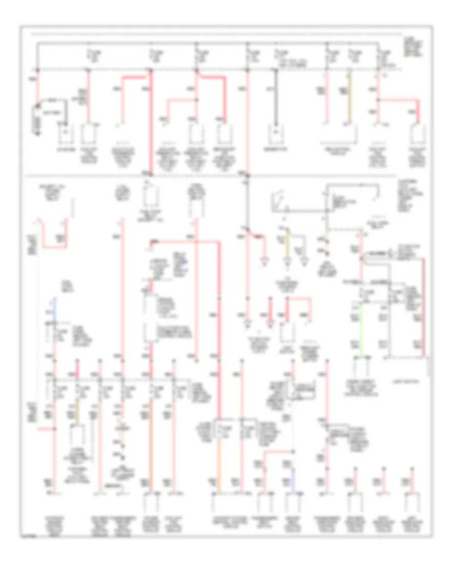
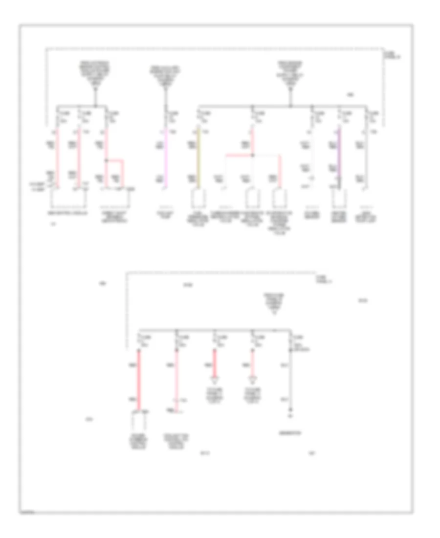
Power Distribution Wiring Diagram, Early Production (1 of 3) for Volkswagen GTI 2006
 https://portal-diagnostov.com/license.html
Automotive Electricians Portal FZCO
Automotive Electricians Portal FZCO
https://portal-diagnostov.com/license.html
https://portal-diagnostov.com/license.html
Automotive Electricians Portal FZCO
Automotive Electricians Portal FZCO
List of elements for Power Distribution Wiring Diagram, Early Production (1 of 3) for Volkswagen GTI 2006:
- (2.0l, 3.2l) (others)
- 12v socket
- 16a
- 28a
- 30a
- 33a
- 35a
- 36a
- 37a
- 44a
- 75x
- Abs control module
- Alarm system & anti- theft fuse
- Battery
- Brake system vacuum pump (1.8l, 2.0l)
- Brake vacuum pump fuse 20a
- Central locking/ anti-theft warning system fuse
- Circuit breaker 30a
- Comfort system central control module
- Coolant fan control module
- Coolant fan control module (1.9l, 2.0l)
- Coolant fan control thermal switch
- Coolant preheating relay (high heat outlet) (1.9l)
- Coolant preheating relay (low heat outlet) (1.9l)
- Diesel direct fuel injection (dfi) engine control module
- Driver's heated seat control module
- Driver's side door control module
- Dual horn relay
- Fuel pump relay
- Fuel pump relay (except 1.9l)
- Fuse 10a
- Fuse 110a
- Fuse 110a 150a
- Fuse 15a
- Fuse 20a
- Fuse 30a
- Fuse 30a (or 40a)
- Fuse 40a
- Fuse 50a
- Fuse 5a
- Fuse bracket/ battery (behind battery)
- Fuse panel (behind left side of dash)
- G42 (below left side of dash)
- G50 (left front of luggage compt)
- Generator
- Glow plug triggering control module (1.9l)
- Headlight dimmer/ flasher switch
- Left rear door control module
- Light switch
- Load reduction relay
- Memory seat control module
- Motronic engine control module (ecm)
- Multi-function steering wheel control module
- Park/ neutral position relay
- Passenger's heated seat control module
- Passenger's seat switch
- Passenger's side door control module
- Power memory seat circuit breaker (in relay panel)
- Power sunroof control module
- Power window circuit breaker (in relay panel)
- Red
- Red red
- Relay panel (under left side of dash)
- Right rear door control module
- Secondary air injection pump relay (except 1.9l)
- Starter
- T14
- T15
- T2b
- T4a
- T60
- T6f
- T8f
- Thirteen -fold auxiliary relay panel
- Thirteen -fold auxiliary relay panel (under left side of dash)
- To fuse panel (diagram 3 of 3)
- To ignition switch (diagram 2 of 3)
- Wiper/ washer intermittent relay
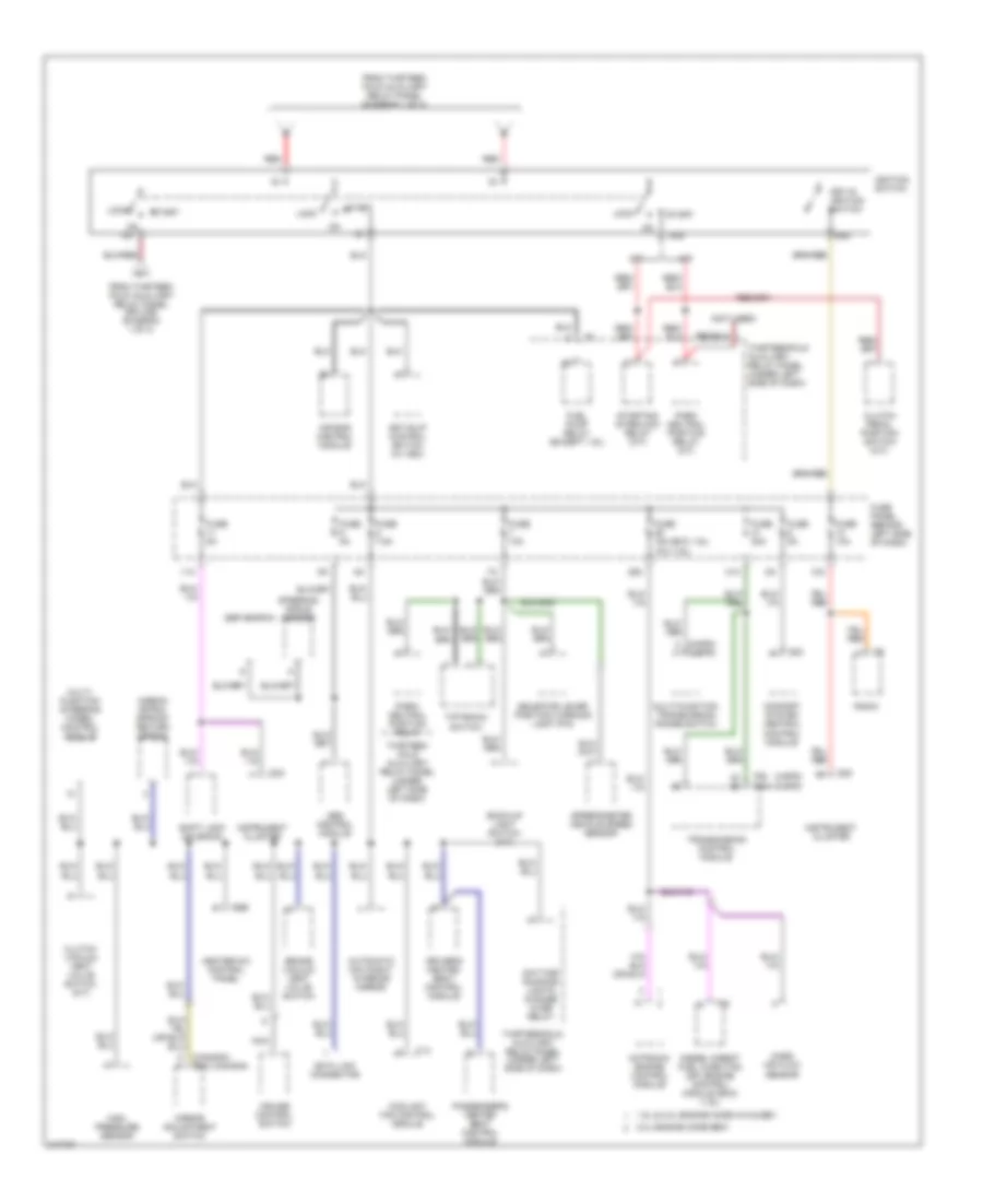
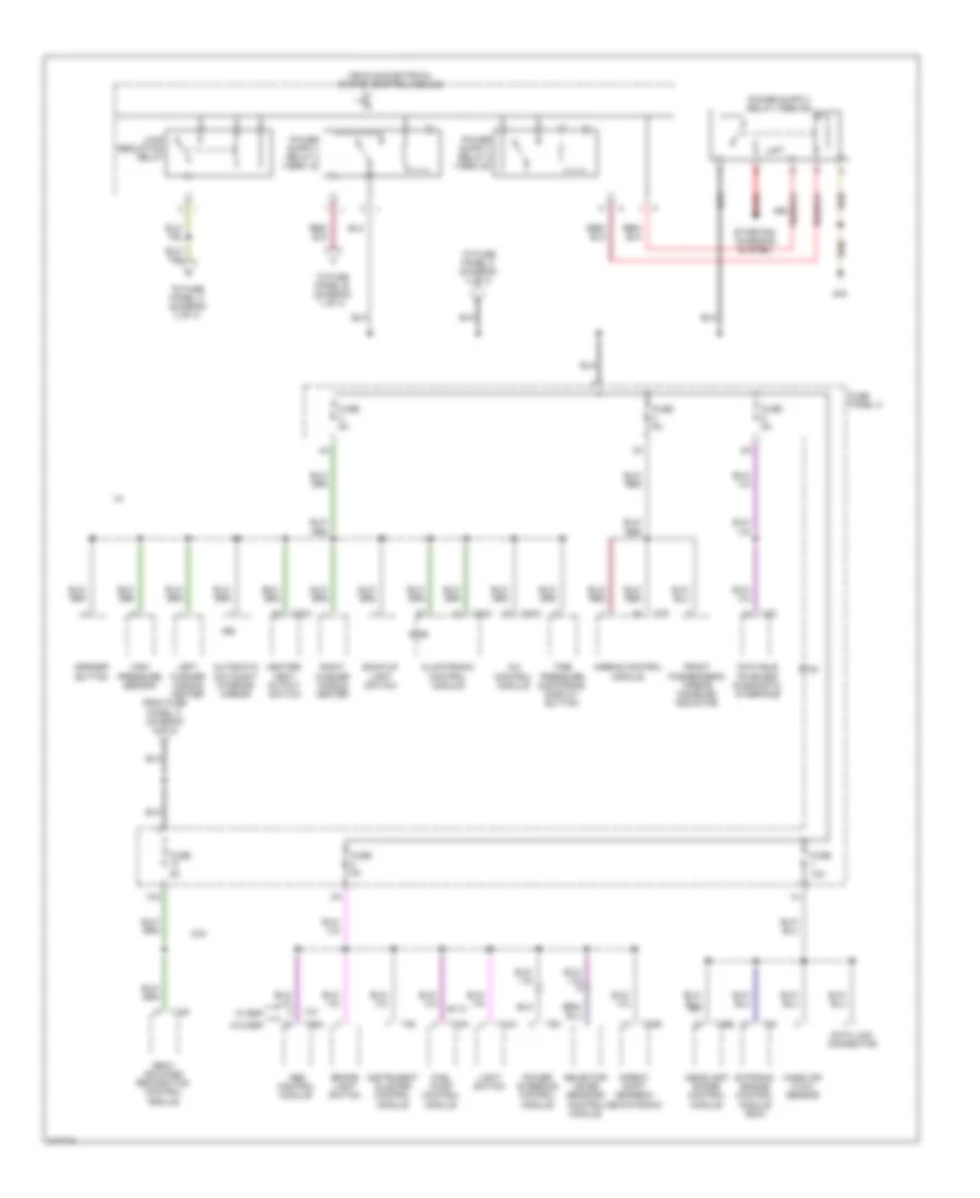
Power Distribution Wiring Diagram, Early Production (2 of 3) for Volkswagen GTI 2006
 https://portal-diagnostov.com/license.html
Automotive Electricians Portal FZCO
Automotive Electricians Portal FZCO
https://portal-diagnostov.com/license.html
https://portal-diagnostov.com/license.html
Automotive Electricians Portal FZCO
Automotive Electricians Portal FZCOList of elements for Power Distribution Wiring Diagram, Early Production (2 of 3) for Volkswagen GTI 2006:
- (1.9l)
- (4-spd)
- (4-spd) (5-spd)
- (5-spd)
- (canada) (exc canada)
- (exc 1.9l)
- (not used)
- 1.8l & 2.0l engine code avh & bev
- 10a
- 11a
- 2.0l engine code bbw
- 29a
- 31a
- 50b
- 75x
- 86s
- A/t
- Abs control module
- Air bag control module
- Airbag spiral spring/ return spring
- Anti-slip control switch (w/ asc)
- Automatic day/night interior mirror
- Back-up light switch (m/t)
- Brake vacuum vent valve switch
- Clutch pedal position switch (m/t)
- Clutch vacuum vent valve switch (m/t)
- Comfort system central control module
- Coolant fan control module
- Cruise control switch
- Data link connector
- Daytime running lights change -over relay
- Diesel direct fuel injection (dfi) engine control module (ecm) (1.9l)
- Driver's heated seat control module
- Esp switch
- From thirteen -fold auxiliary relay panel (diagram 1 of 3)
- From thirteen -fold auxiliary relay panel (splice) (diagram 1 of 3)
- Fuel pump relay (except 1.9l)
- Fuse 10a
- Fuse 15a
- Fuse 20a
- Fuse 5a
- Fuse 7.5a
- Fuse panel (behind left side of dash)
- Heater-a/c control panel
- High pressure sensor
- Ignition switch
- Instrument cluster
- Key-in ignition switch
- Lock
- M/t
- Mass air flow sensor
- Mirror adjustment switch
- Motronic engine control module
- Multi- function steering wheel control module
- Multi-function transmission range switch
- Nca
- Park neutral position relay (a/t)
- Park/ neutral position relay
- Passenger's heated seat control module
- Radio
- Red
- Selector lever position warning light (p/n)
- Shift lock solenoid
- Speedometer vehicle speed sensor
- Start
- Starting interlock relay (m/t)
- Steering angle sensor
- T14
- T23
- T32
- T68 t68a
- T8b
- T94
- Thirteen -fold auxiliary relay panel (under left side of dash)
- Thirteenfold auxiliary relay panel (under left side of dash)
- Tiptronic switch
- Transmission control module
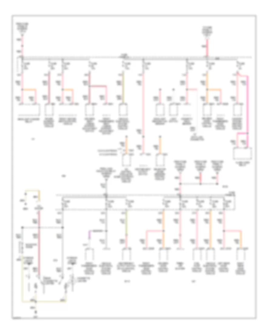
Power Distribution Wiring Diagram, Early Production (3 of 3) for Volkswagen GTI 2006
 https://portal-diagnostov.com/license.html
Automotive Electricians Portal FZCO
Automotive Electricians Portal FZCO
https://portal-diagnostov.com/license.html
https://portal-diagnostov.com/license.html
Automotive Electricians Portal FZCO
Automotive Electricians Portal FZCOList of elements for Power Distribution Wiring Diagram, Early Production (3 of 3) for Volkswagen GTI 2006:
- (4-spd)
- (5-spd)
- 12a
- 13a
- 14a
- 15a
- 24a
- 25a
- 26a
- 27a
- 38a
- 39a
- 40a
- 42a
- Amplifier (monsoon)
- Brake- light switch
- Cigarette lighter
- Comfort system central control module
- Data link connector
- Driver's side door control module
- Dual horn relay
- Emergency flasher switch
- Except monsoon
- From thirteen- fold auxiliary relay panel (diagram 1 of 3)
- From thirteen-fold auxiliary relay panel (diagram 1 of 3)
- Fuse 10a
- Fuse 15a
- Fuse 20a
- Fuse 25a
- Fuse 5a
- Fuse 7.5a
- Fuse panel (behind left side of dash)
- G42 (below left side of dash)
- Glove compartment light
- Heater-a/c control panel
- Instrument cluster
- Interior lights system
- Left rear door control module
- Left washer heater nozzle
- Memory seat control module
- Monsoon
- Passenger's side door control module
- Radio
- Rear window defogger switch
- Rear window wiper fuse
- Rear windshield wiper motor (golf)
- Red
- Remote/ fuel tank door switch
- Right rear door control module
- Right washer heater nozzle
- Steering angle sensor
- T23
- T28
- T32
- T6d
- T8 t16d
- Thirteenfold auxiliary relay panel (under left side of dash)
- Transmission control module
- Windshield wiper/washer switch
- Wiper/washer intermittent relay
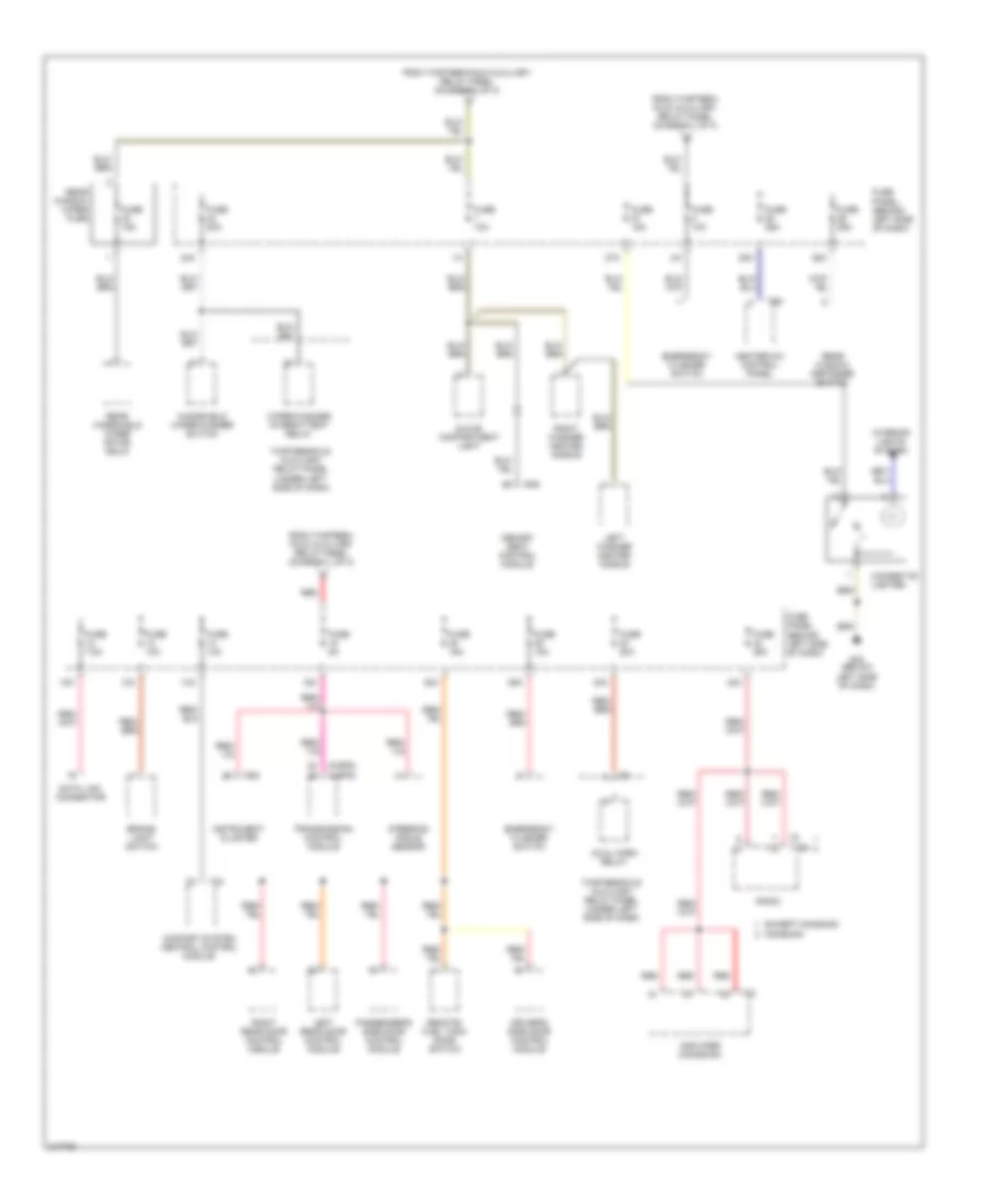
Power Distribution Wiring Diagram, Late Production (1 of 4) for Volkswagen GTI 2006
 https://portal-diagnostov.com/license.html
Automotive Electricians Portal FZCO
Automotive Electricians Portal FZCO
https://portal-diagnostov.com/license.html
https://portal-diagnostov.com/license.html
Automotive Electricians Portal FZCO
Automotive Electricians Portal FZCOList of elements for Power Distribution Wiring Diagram, Late Production (1 of 4) for Volkswagen GTI 2006:
- (diagram 2 of 4)
- A/30
- A68
- A81
- A98
- Auxiliary engine coolant pump relay
- B110
- B138
- B156
- Battery
- Camshaft adjustment valve 1
- Clutch position sensor
- Comfort system central control module
- Coolant fan control module
- D78
- Data bus on board diagnostic interface
- From fuse panel b (diagram 1 of 4)
- Fuse 10a
- Fuse 15a
- Fuse 20a
- Fuse 25a
- Fuse 30a
- Fuse 40a
- Fuse 50a
- Fuse 5a
- Fuse panel b
- G12 (left front of engine compt)
- Ignition coil 1
- Ignition coil 2
- Ignition coil 3
- Ignition coil 4
- Instrument cluster control module
- L/30
- M/30
- Motronic engine control module
- Motronic engine control module (ecm)
- Radio/ navigation display control module
- Red
- Satellite radio
- Starting/charging system
- Steering column electronic systems control module
- T16b
- T18
- T20d
- T26
- T36
- T40
- T8b
- T94
- To fuse panel a (diagram 2 of 4)
- To fuse panel b (diagram 1 of 4)
- To fuse panel b (diagram 2 of 4)
- To fuse panel b e
- To fuse panel b f
- To fuse panel c (diagram 3 of 4)
- Vehicle electrical system control module
- Wiper motor control module
Power Distribution Wiring Diagram, Late Production (2 of 4) for Volkswagen GTI 2006
 https://portal-diagnostov.com/license.html
Automotive Electricians Portal FZCO
Automotive Electricians Portal FZCO
https://portal-diagnostov.com/license.html
https://portal-diagnostov.com/license.html
Automotive Electricians Portal FZCO
Automotive Electricians Portal FZCOList of elements for Power Distribution Wiring Diagram, Late Production (2 of 4) for Volkswagen GTI 2006:
- A68
- A81
- A98
- Abs control module
- B110
- B138
- B156
- Coolant fan control (fc) control module
- Coolant pump
- D78
- Direct shift gearbox mechatronic
- Evaporative emission canister purge regulator valve
- From auxiliary engine coolant pump relay diagram (1 of 4)
- From fuse panel b diagram (1 of 4)
- Fuel pressure regulator valve
- Fuse 10a
- Fuse 150a (or 200a)
- Fuse 15a
- Fuse 30a
- Fuse 50a
- Fuse 80a
- Fuse panel a
- Fuse panel b
- Generator
- Heated oxygen sensor
- Leak detection pump (ldp)
- Nca
- Oxygen sensor
- Power steering control module
- Red
- T20e
- T26
- T2a
- T40
- T47
- T4x
- To fuse panel c (diagram 3 of 4)
- Turbocharger recirculating valve
- W/ esp
- W/o esp
- Wastegate bypass regulator valve
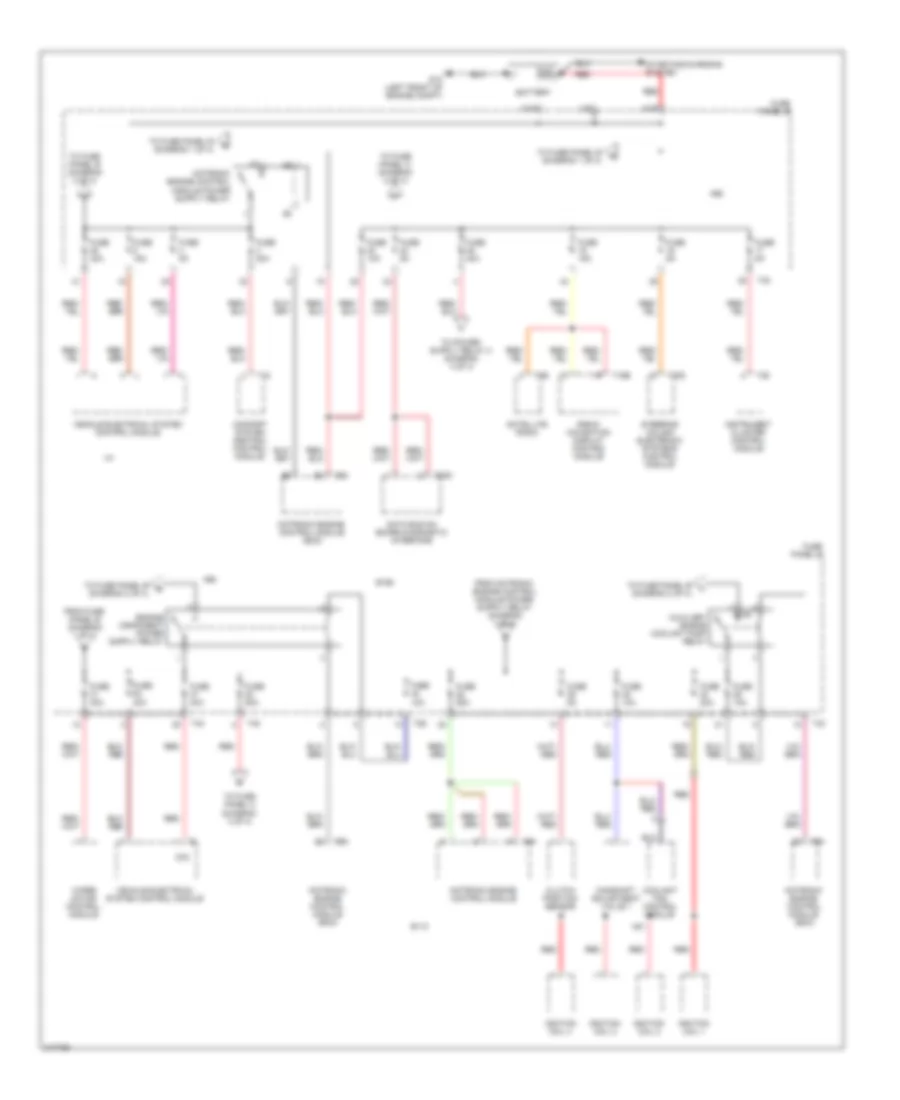
Power Distribution Wiring Diagram, Late Production (3 of 4) for Volkswagen GTI 2006
 https://portal-diagnostov.com/license.html
Automotive Electricians Portal FZCO
Automotive Electricians Portal FZCO
https://portal-diagnostov.com/license.html
https://portal-diagnostov.com/license.html
Automotive Electricians Portal FZCO
Automotive Electricians Portal FZCOList of elements for Power Distribution Wiring Diagram, Late Production (3 of 4) for Volkswagen GTI 2006:
- 12a
- 12v socket
- 13a
- 14a
- 15a
- 17a
- 22a
- 23a
- 25a
- 26a
- 27a
- 32a
- 33a
- 36a
- 37a
- 40a
- 42a
- A/c control module or climatronic control module
- A68
- A81
- A98
- Alarm horn relay
- B110
- B138
- B156
- Blocking diode
- Cigarette lighter
- Comfort system central control module
- D78
- Data link connector
- Driver's door control module
- Driver's seat lumbar support adjustment switch
- Fresh air blower
- From fuse panel a (diagram 2 of 4)
- From fuse panel b (diagram 1 of 4)
- From fuse panel c (diagram 3 of 4)
- From load induction relay (diagram 4 of 4)
- Front heated seats control module
- Front passenger's door control module
- Front passenger's seat lumbar support adjustment switch
- Fuel pump control module
- Fuse 10a
- Fuse 15a
- Fuse 20a
- Fuse 25a
- Fuse 30a
- Fuse 40a
- Fuse 5a
- Fuse 7.5a
- Fuse panel c
- G47
- G682
- Headlamp washer relay
- Heater/heat output switch
- Heater/heat output switch or a/c control module
- Interior lights system
- Left rear door control module
- Light switch
- Magnetic field sensor
- Power sunroof control module
- Rain/light recognition sensor
- Rear cigarette lighter
- Red
- Right rear door control module
- Selector lever sensors control module
- T10h
- T10n
- T18
- T18c
- T18d
- T20a
- T20b
- T20c
- T6ah
- T6ai
- T6c
- T8z
- To fuse panel c (diagram 3 of 4)
- Vehicle electrical system control module
- W/ climatronic
- W/o climatronic
Power Distribution Wiring Diagram, Late Production (4 of 4) for Volkswagen GTI 2006
 https://portal-diagnostov.com/license.html
Automotive Electricians Portal FZCO
Automotive Electricians Portal FZCO
https://portal-diagnostov.com/license.html
https://portal-diagnostov.com/license.html
Automotive Electricians Portal FZCO
Automotive Electricians Portal FZCOList of elements for Power Distribution Wiring Diagram, Late Production (4 of 4) for Volkswagen GTI 2006:
- 10a
- A/c control module
- A68
- A81
- A98
- Abs control module
- Airbag control module
- Asr/esp button
- Automatic day/night interior mirror
- B110
- B138
- B156
- Back-up light switch
- Brake light switch
- Climatronic control module
- D78
- Data bus on board diagnostic interface
- Data link connector
- Direct shift gearbox mechatronic
- From fuse panel c (diagram 4 of 4)
- Front passenger's airbag disabled indicator
- Fuel pump control module
- Fuse 10a
- Fuse 5a
- Fuse panel c
- G44
- Headlamp range control module
- Heater/ heat output switch
- High pressure sensor
- Instrument cluster control module
- Left washer nozzle heater
- Light switch
- Load reduction relay
- Mass air flow sensor
- Motronic engine control module (ecm)
- Power steering control module
- Red
- Right washer nozzle heater
- Seat occupied recognition control module
- Selector lever sensors control module
- Starting/ charging system
- T10h
- T10n
- T18f
- T20
- T20c
- T20e
- T26a
- T26b
- T36
- T47
- T5h
- T75
- T94
- Tire pressure monitoring display button
- To fuse panel b (diagram 1 of 4)
- To fuse panel c (diagram 3 of 4)
- To fuse panel c (diagram 4 of 4)
- Vehicle electrical system control module
- W/ esp
- W/o esp

 Čeština
 Dansk
Dansk Deutsch
 Ελληνικά
 English
 English
 Español
 Suomi
Suomi Français
 Français
 עברית
עברית Hrvatski
 Magyar
 Italiano
 日本語
日本語 Nederlands
 Polski
 Português
 Português
 Română
 Русский
 Slovenčina
 Slovenščina
 Svenska
 Türkçe
 中文 (中国)
