СИСТЕМА ПЕРЕДАЧИ ДАННЫХ
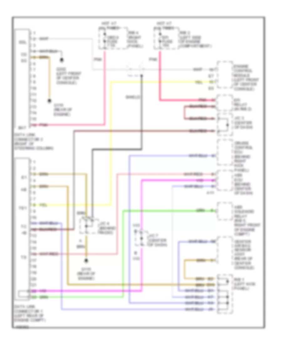
Электросхема компьютерной линии передачи данных CAN для Toyota Celica GT 1999
 https://portal-diagnostov.com/license.html
Automotive Electricians Portal FZCO
Automotive Electricians Portal FZCO
https://portal-diagnostov.com/license.html
https://portal-diagnostov.com/license.html
Automotive Electricians Portal FZCO
Automotive Electricians Portal FZCO
Электросхема компьютерной линии передачи данных CAN для Toyota Celica GT 1999 - Список элементов:
- A11
- Abs ecu (behind center of dash)
- Abs solenoid relay (r/b 5, right front of engine compt)
- All times
- Bat
- Center air bag sensor assy (rear of center console)
- Cruise control ecu (behind right kick panel)
- D10
- Data link connector 1 (left rear of engine compt)
- Data link connector 3 (right of steering column)
- Efi fuse 15a
- Efi relay (in r/b 2)
- Engine control module (left front of center console)
- G115 (rear of engine)
- G302 (left front of center console)
- Hot at
- J/c 3 (center of dash)
- J/c 4 (behind radio)
- J/c 7 (center of dash)
- Obd ii fuse 7.5a
- Pnk
- R/b 1 (left kick panel)
- R/b 2 (left side of engine compartment)
- R/b 4 (right kick panel)
- Sdl
- Shield
- Te1
 Čeština
 Dansk
Dansk Deutsch
 Ελληνικά
 English
 English
 Español
 Suomi
Suomi Français
 Français
 עברית
עברית Hrvatski
 Magyar
 Italiano
 日本語
日本語 Nederlands
 Polski
 Português
 Português
 Română
 Русский
 Slovenčina
 Slovenščina
 Svenska
 Türkçe
 中文 (中国)
 한국어
한국어
