SUPPLEMENTAL RESTRAINTS
Supplemental Restraints Wiring Diagram (1 of 2) for Toyota Prius 2005

List of elements for Supplemental Restraints Wiring Diagram (1 of 2) for Toyota Prius 2005:
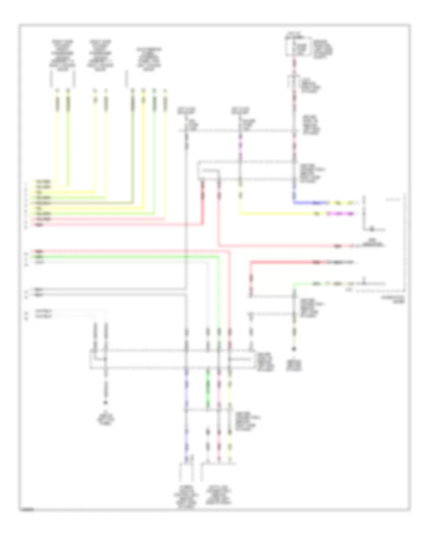
Supplemental Restraints Wiring Diagram (2 of 2) for Toyota Prius 2005
List of elements for Supplemental Restraints Wiring Diagram (2 of 2) for Toyota Prius 2005: