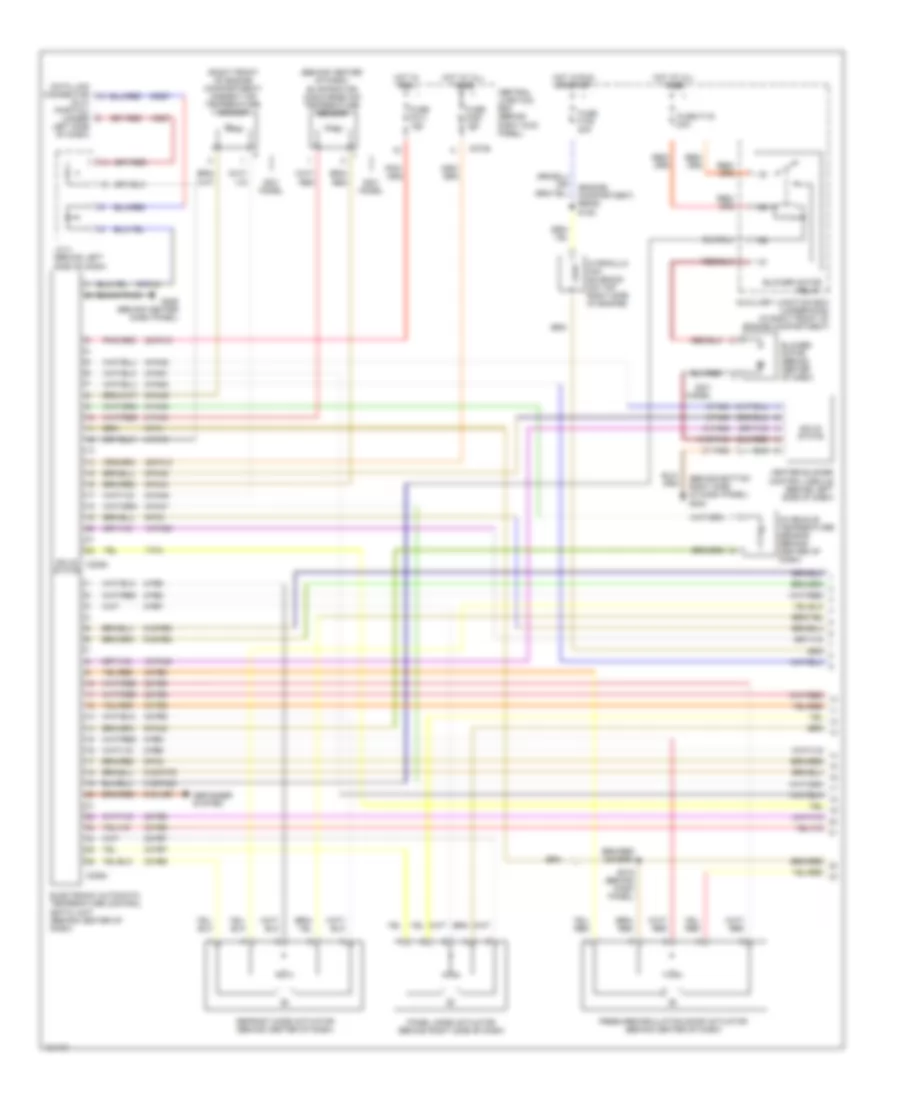
AIR CONDITIONING
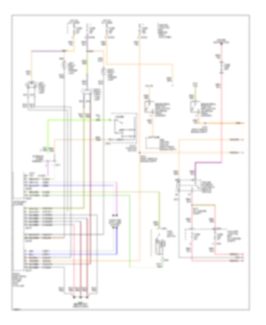
Automatic A/C Wiring Diagram (1 of 2) for Lincoln LS 2001
 https://portal-diagnostov.com/license.html
Automotive Electricians Portal FZCO
Automotive Electricians Portal FZCO
https://portal-diagnostov.com/license.html
https://portal-diagnostov.com/license.html
Automotive Electricians Portal FZCO
Automotive Electricians Portal FZCO
List of elements for Automatic A/C Wiring Diagram (1 of 2) for Lincoln LS 2001:
- (behind bottom right side of dash panel) g203
- (behind center of dash) evaporator discharge air temperature sensor
- (dlc) (partial) (under left side of dash)
- (engine compartment, rear) s125
- (right front of engine compartment) ambient air temperature sensor
- 10-fa45
- 10-fa53
- 20-fa10
- 29-fa10
- 31-fa10
- 31-fa45
- 31s-fa18
- 31s-fa23
- 32-fb2
- 32-fb5
- 32-fb6
- 32-fb7
- 32-fb8
- 33-fb2
- 33-fb5
- 33-fb6
- 33-fb7
- 33-fb8
- 4-eg7
- 4-fa10
- 5-eg7
- 5-fa10
- 7-fa1
- 8-fa44
- 8-fa45
- 8-fa47
- 8-fa48
- 8-fa49
- 8-fa51
- 8-fa53
- 8-fb2
- 8-fb5
- 8-fb6
- 8-fb7
- 8-fb8
- 9-fa1
- 9-fa2
- 9-fa3
- 9-fa44
- 9-fa45
- 9-fa48
- 9-fa49
- 91s-fa76
- 91s-fb3
- 91s-fb4
- 91s-hb7
- Auxiliary junction box (underhood) (in right front of engine compartment)
- Blower motor (behind center of dash)
- Blower motor relay
- C228a
- C228b
- C270a
- Central junction box (behind right kick panel)
- Data link connector
- Defogger system
- Defrost mode actuator (behind center of dash)
- Electronic automatic temperature control (eatc) unit (behind center of dash)
- Fresh/recirculation door actuator (behind center of dash)
- Fuse f105 20a
- Fuse f116 30a
- Fuse f214 10a
- Fuse f220 10a
- G206 (behind center dash panel)
- Heater blower control module (behind left side of dash)
- Hot at all times
- Hot in run
- Hot in run or start
- Hydraulic fan solenoid (on top right side of engine)
- In-vehicle temperature sensor (behind center of dash)
- J/c 4 (behind left side of dash)
- Model
- Panel mode actuator (behind right side of dash)
- S215 (behind dash panel)
- Solid state
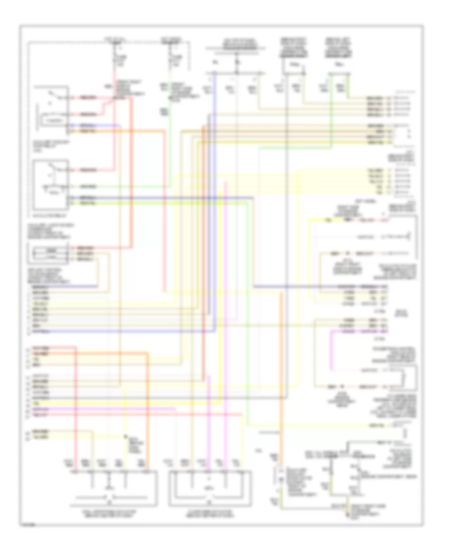
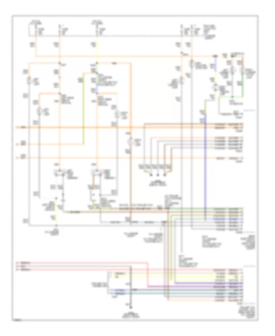
Automatic A/C Wiring Diagram (2 of 2) for Lincoln LS 2001
 https://portal-diagnostov.com/license.html
Automotive Electricians Portal FZCO
Automotive Electricians Portal FZCO
https://portal-diagnostov.com/license.html
https://portal-diagnostov.com/license.html
Automotive Electricians Portal FZCO
Automotive Electricians Portal FZCOList of elements for Automatic A/C Wiring Diagram (2 of 2) for Lincoln LS 2001:
- (behind left side of dash) discharge temperature sensor (left)
- (behind right side of dash) discharge temperature sensor (right)
- (front right side of red
- (on top of dash, above glove box) sunload sensor
- (right side of engine compartment) s103
- 2000: 3.0l engine
- 2001 model
- 2001: all models 2000: 3.9l engine
- 3.9l
- 7-re8
- 8-fa88
- 8-rj33
- 9-re8
- 91s-fa79
- 91s-rg1
- A/c clutch cycling pressure switch (in left front of engine compartment)
- A/c clutch relay
- A/c clutch solenoid (in left side of engine compartment)
- Auxiliary coolant pump motor (in right front of engine compartment)
- Auxiliary coolant pump relay (3.9l)
- Auxiliary junction box (underhood) (in right front of engine compartment)
- C175a
- C175c
- Cool air bypass actuator (behind center of dash)
- Coolant control valve solenoid (in right front of engine compartment)
- Cylinder head temperature sensor (3.0l: on middle of left cylinder head) (3.9l: on right cylinder head, under intake)
- Engine compartment) s136
- Floor mode actuator (behind center of dash)
- Fuse f101 10a
- Fuse f111 15a
- Hot at all times
- Hot in run or start
- J/c 1 (behind right side of dash)
- J/c 2 (behind right side of dash)
- Powertrain control module (pcm) (right rear of engine compartment)
- Right side of engine compartment) s135
- S113 (right front side of engine compartment)
- S126 (engine compartment, rear)
- S216 (behind dash panel)
- Solid state
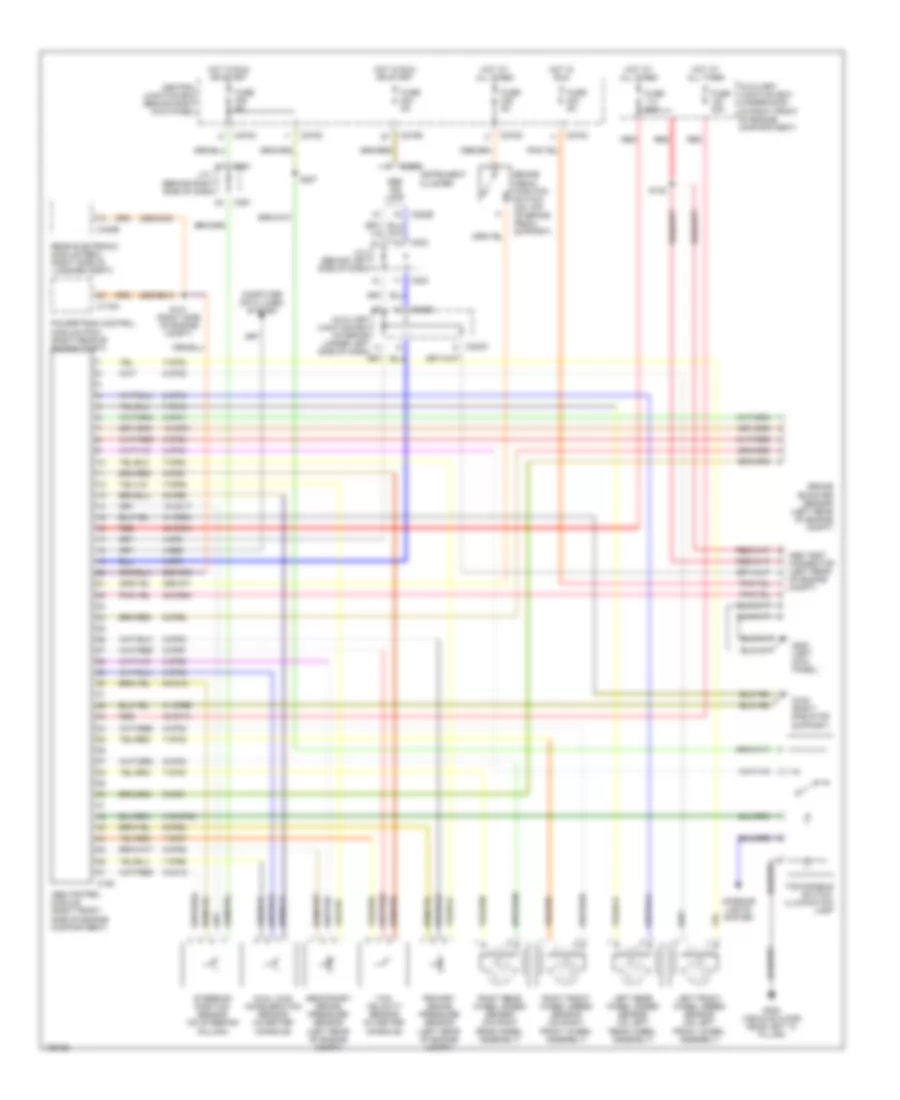
ANTI-LOCK BRAKES
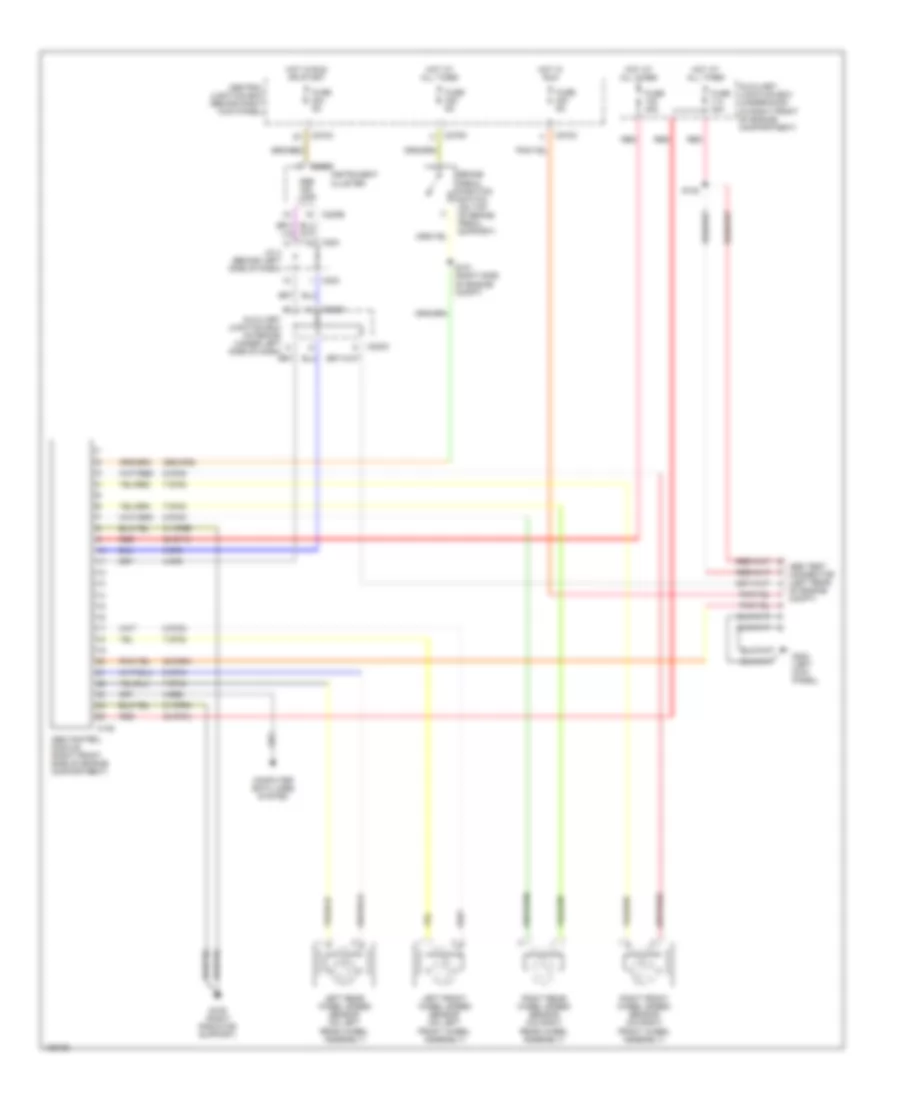
Anti-lock Brakes Wiring Diagram, with Traction Control & Stability Assist for Lincoln LS 2001
 https://portal-diagnostov.com/license.html
Automotive Electricians Portal FZCO
Automotive Electricians Portal FZCO
https://portal-diagnostov.com/license.html
https://portal-diagnostov.com/license.html
Automotive Electricians Portal FZCO
Automotive Electricians Portal FZCOList of elements for Anti-lock Brakes Wiring Diagram, with Traction Control & Stability Assist for Lincoln LS 2001:
- 10-cc17
- 10-cf51
- 20-cf6a
- 29s-cf1
- 29s-cf2
- 29s-dk30
- 29s-re13
- 30-cf13
- 30-cf6a
- 31-cf6a
- 31-cf6b
- 31s-cf45
- 4-cf6
- 4-ee6
- 5-cf6
- 7-cf32
- 7-cf34
- 7-cf38
- 7-cf40
- 7-cf64
- 7-cf65
- 7-cf66
- 7-cf67
- 8-cc18
- 8-cf32
- 8-cf34
- 8-cf38
- 8-cf40
- 8-cf51
- 8-cf54
- 8-cf64
- 8-cf65
- 8-cf66
- 8-cf67
- 8-cf68
- 9-cc16
- 9-cf51
- 9-cf64
- 9-cf65
- 9-cf66
- 9-cf67
- 9-cf68
- Abs control module (right front side of engine compartment)
- Abs ind lamp
- Abs test connector (left rear
- Auxiliary junction box (interior) (under left side of dash)
- Auxiliary junction box (underhood) (in right front of engine compartment)
- Brake booster sensor (left rear of engine compt)
- Brake pedal position switch (on top of brake pedal support)
- C155
- C175a
- C220b
- C223
- C261
- C270a
- C270b
- C270c
- C270d
- C283c
- C283d
- C420b
- Central junction box (behind right kick panel)
- Computer data lines system
- Dual axis acceleration sensor (in center console)
- Fuse 30a
- Fuse 5a
- G109 (right radiator support)
- G200 (left kick panel)
- G300 (vehicle floor, near left "c" pillar)
- Hot at all times
- Hot in run
- Hot in run or start
- Instrument cluster
- Interior lights system
- J/c 1 (behind right side of dash)
- J/c 4 (behind left side of dash)
- Left front wheel speed sensor (on left front wheel assembly)
- Left rear wheel speed sensor (on left rear wheel assembly)
- Of engine compt)
- Powertrain control module (pcm) (right rear of engine compt)
- Primary brake pressure sensor (left rear of engine compt)
- Rear electronic module (rem) (right side of luggage compt)
- Red
- Right front wheel speed sensor (on right front wheel assembly)
- Right rear wheel speed sensor (on right rear wheel assembly)
- S101 (right side of engine compt)
- S122
- S207
- Secondary brake pressure sensor (left rear of engine compt)
- Steering position sensor (on steering column)
- Tcs disable switch/ illumination lamp
- Yaw velocity sensor (in center console)
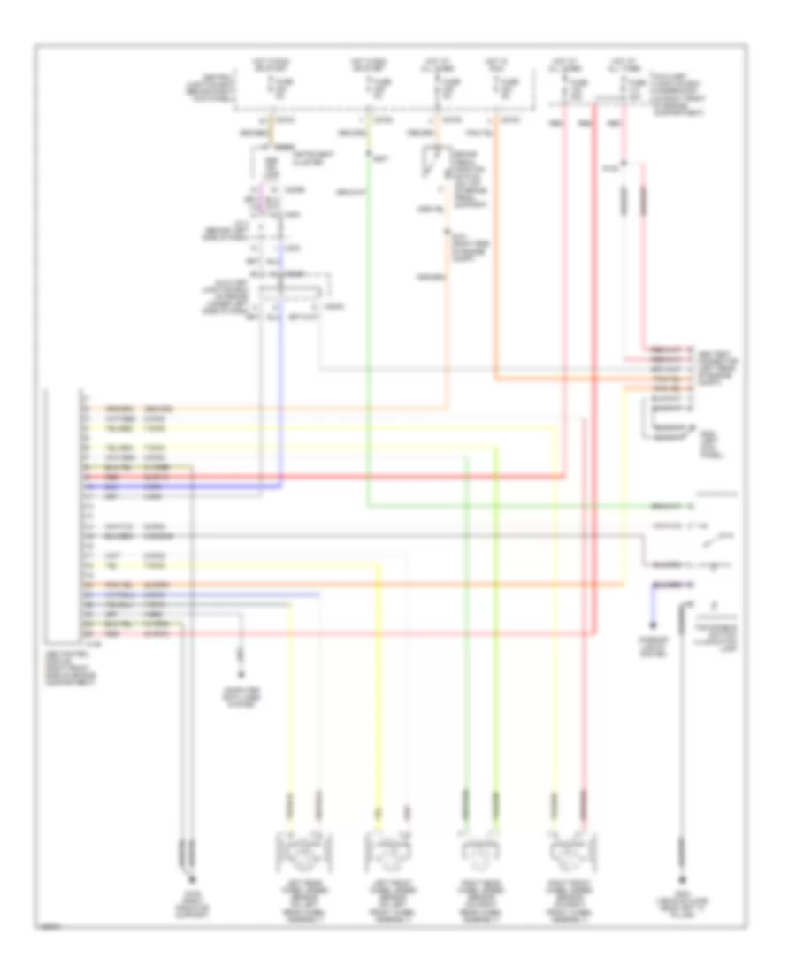
Anti-lock Brakes Wiring Diagram, with Traction Control for Lincoln LS 2001
 https://portal-diagnostov.com/license.html
Automotive Electricians Portal FZCO
Automotive Electricians Portal FZCO
https://portal-diagnostov.com/license.html
https://portal-diagnostov.com/license.html
Automotive Electricians Portal FZCO
Automotive Electricians Portal FZCOList of elements for Anti-lock Brakes Wiring Diagram, with Traction Control for Lincoln LS 2001:
- 20-cf6a
- 29s-cf58
- 30-cf13
- 30-cf6a
- 31-cf6a
- 31-cf6b
- 31s-cf45
- 4-cf6
- 4-ee6
- 5-cf6
- 7-cf32
- 7-cf34
- 7-cf38
- 7-cf40
- 8-cf32
- 8-cf34
- 8-cf38
- 8-cf40
- 8-cf54
- Abs control module (right front side of engine compartment)
- Abs ind lamp
- Abs test connector (left rear
- Auxiliary junction box (interior) (under left side of dash)
- Auxiliary junction box (underhood) (in right front of engine compartment)
- Brake pedal position switch (on top of brake pedal support)
- C135
- C220b
- C223
- C270a
- C270c
- C270d
- C283c
- C283d
- Central junction box (behind right kick panel)
- Computer data lines system
- Fuse 30a
- Fuse 5a
- G109 (right radiator support)
- G200 (left kick panel)
- G300 (vehicle floor, near left "c" pillar)
- Hot at all times
- Hot in run
- Hot in run or start
- Instrument cluster
- Interior lights system
- J/c 4 (behind left side of dash)
- Left front wheel speed sensor (on left front wheel assembly)
- Left rear wheel speed sensor (on left rear wheel assembly)
- Of engine compt)
- Red
- Right front wheel speed sensor (on right front wheel assembly)
- Right rear wheel speed sensor (on right rear wheel assembly)
- S101 (right side of engine compt)
- S122
- S207
- Tcs disable switch/ illumination lamp
Anti-lock Brakes Wiring Diagram, without Traction Control for Lincoln LS 2001
 https://portal-diagnostov.com/license.html
Automotive Electricians Portal FZCO
Automotive Electricians Portal FZCO
https://portal-diagnostov.com/license.html
https://portal-diagnostov.com/license.html
Automotive Electricians Portal FZCO
Automotive Electricians Portal FZCOList of elements for Anti-lock Brakes Wiring Diagram, without Traction Control for Lincoln LS 2001:
- 20-cf6a
- 29s-cf58
- 30-cf13
- 30-cf6a
- 31-cf6a
- 31-cf6b
- 4-cf6
- 4-ee6
- 5-cf6
- 7-cf32
- 7-cf34
- 7-cf38
- 7-cf40
- 8-cf32
- 8-cf34
- 8-cf38
- 8-cf40
- Abs control module (right front side of engine compartment)
- Abs ind lamp
- Abs test connector (left rear
- Auxiliary junction box (interior) (under left side of dash)
- Auxiliary junction box (underhood) (in right front of engine compartment)
- Brake pedal position switch (on top of brake pedal support)
- C135
- C220b
- C223
- C270a
- C270c
- C270d
- C283c
- C283d
- Central junction box (behind right kick panel)
- Computer data lines system
- Fuse 30a
- Fuse 5a
- G109 (right radiator support)
- G200 (left kick panel)
- Hot at all times
- Hot in run
- Hot in run or start
- Instrument cluster
- J/c 4 (behind left side of dash)
- Left front wheel speed sensor (on left front wheel assembly)
- Left rear wheel speed sensor (on left rear wheel assembly)
- Of engine compt)
- Red
- Right front wheel speed sensor (on right front wheel assembly)
- Right rear wheel speed sensor (on right rear wheel assembly)
- S101 (right side of engine compt)
- S122
ANTI-THEFT
Forced Entry Wiring Diagram for Lincoln LS 2001
 https://portal-diagnostov.com/license.html
Automotive Electricians Portal FZCO
Automotive Electricians Portal FZCO
https://portal-diagnostov.com/license.html
https://portal-diagnostov.com/license.html
Automotive Electricians Portal FZCO
Automotive Electricians Portal FZCOList of elements for Forced Entry Wiring Diagram for Lincoln LS 2001:
- 20-dk20
- 29-aj80
- 29s-aj86
- 29s-dk31
- 31-gl47
- 31-gl58
- 31s-aa78
- 31s-aa79
- 31s-gl12
- 31s-gl19
- 31s-gl46
- 4-eg11
- 4-eg12
- 4-eg13
- 5-eg11
- 5-eg12
- 5-eg13
- 75-gl58
- 8-gl20
- 8-gl7
- 91-aj80
- 91s-gj7
- 91s-gl13
- Anti-theft hood switch
- Auxiliary junction box (underhood) (in right front of eng compt)
- Battery junction box (in luggage compt, near battery)
- C201a
- C201c
- C201e
- C201f
- C270d
- C270e
- C420a
- C420b
- C420c
- C420d
- C501a
- C501c
- Central junction box (behind right kick panel)
- Computer data lines system
- Driver door lock unit
- Driver door module (in driver door)
- Front electronic module (left "a" pillar)
- Front passenger door lock unit
- Fuse f104 15a
- Fuse f207 5a
- Fuse f222 10a
- Fuse f229 5a
- Fuse f401 15a
- G108 (left radiator support)
- G200 (left kick panel)
- G203 (right kick panel)
- G313 (right side of rear sheld)
- G404 (left rear side of trunk)
- Horn
- Horn relay
- Hot at all times
- Hot in run
- Left rear door lock actuator
- Luggage compartment lid ajar switch
- Rear electronic module (right side of luggage compt)
- Red
- Reset
- Right rear door lock actuator
- S139
- S210
- S228
- S504
- Set
- Steering column lock
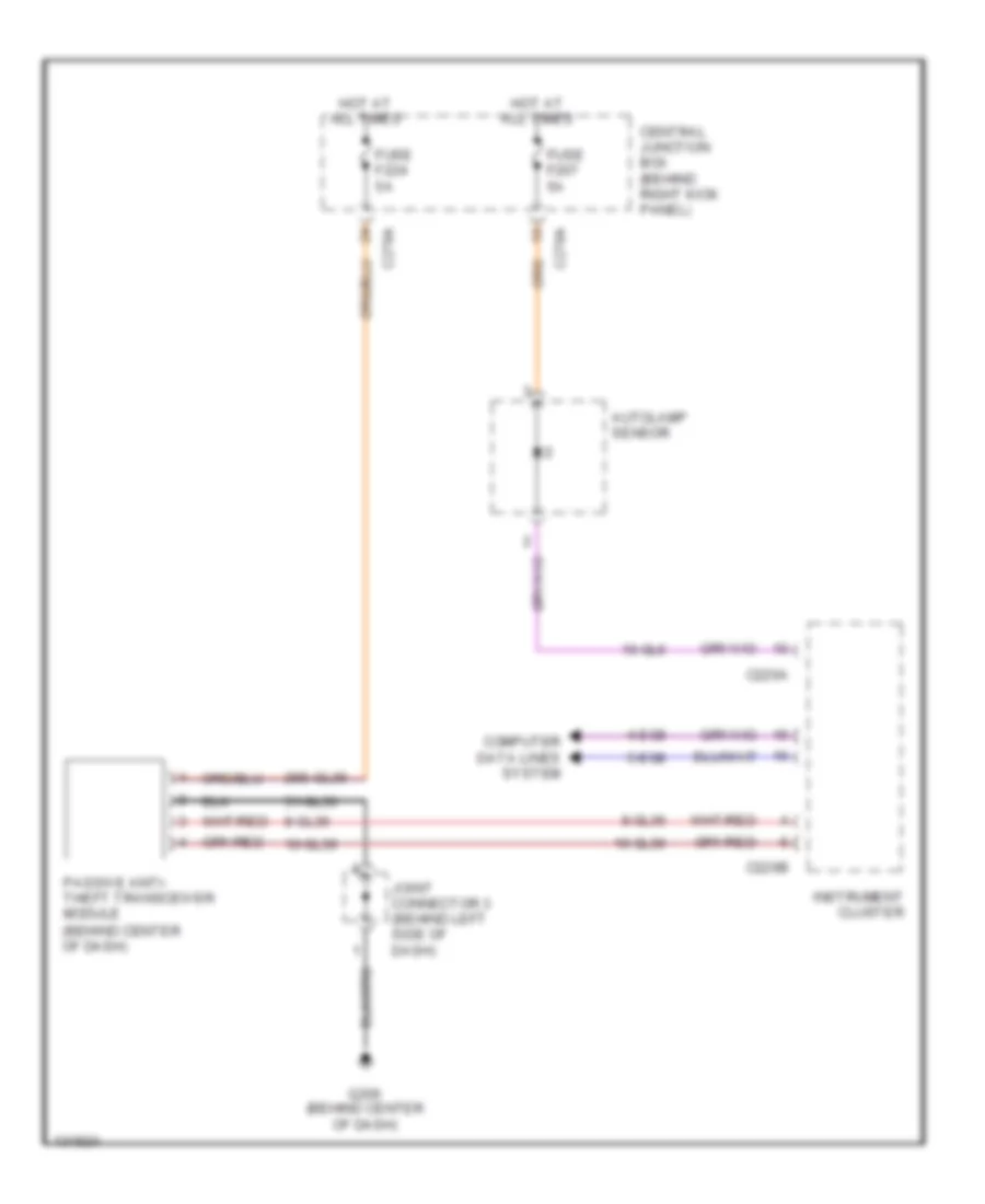
Passive Anti-theft Wiring Diagram for Lincoln LS 2001
 https://portal-diagnostov.com/license.html
Automotive Electricians Portal FZCO
Automotive Electricians Portal FZCO
https://portal-diagnostov.com/license.html
https://portal-diagnostov.com/license.html
Automotive Electricians Portal FZCO
Automotive Electricians Portal FZCOList of elements for Passive Anti-theft Wiring Diagram for Lincoln LS 2001:
- 10-gl36
- 10-gl6
- 29s-gl36
- 31-gl36
- 4-eg8
- 5-eg8
- 8-gl36
- Autolamp sensor
- C220a
- C220b
- C270a
- Central junction box (behind right kick panel)
- Computer data lines system
- Fuse f207 5a
- Fuse f224 5a
- G206 (behind center of dash)
- Hot at all times
- Instrument cluster
- Joint connector 3 (behind left side of dash)
- Passive anti- theft transceiver module (behind center of dash)
BODY CONTROL MODULES
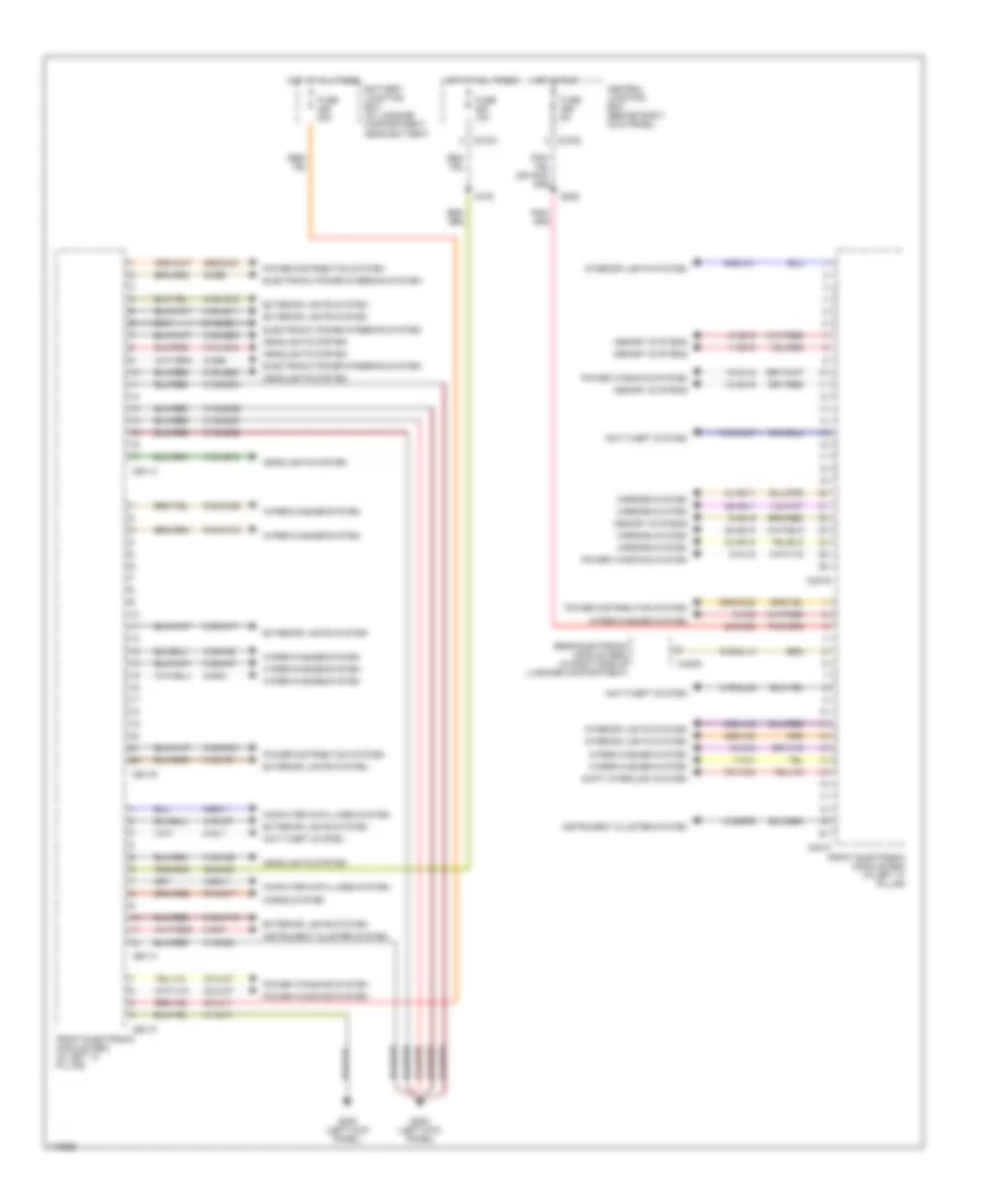
Body Control Modules Wiring Diagram (1 of 2) for Lincoln LS 2001
 https://portal-diagnostov.com/license.html
Automotive Electricians Portal FZCO
Automotive Electricians Portal FZCO
https://portal-diagnostov.com/license.html
https://portal-diagnostov.com/license.html
Automotive Electricians Portal FZCO
Automotive Electricians Portal FZCOList of elements for Body Control Modules Wiring Diagram (1 of 2) for Lincoln LS 2001:
- 10-ad19
- 10-aj18
- 10-ka3
- 20-dk20
- 29-dk20
- 29s-dk21
- 29s-dk22
- 29s-lc3
- 30-aj71
- 31-aj71
- 31-dk20
- 31-dk20a
- 31-dk20b
- 31-dk20c
- 31-dk20d
- 31-gl58
- 31s-dk21
- 31s-gl46
- 31s-gl47
- 31s-ka7
- 31s-ka8
- 31s-ld9
- 31s-le15
- 31s-le16
- 31s-le22
- 31s-le23
- 31s-lf16
- 31s-lf17
- 31s-lf7
- 31s-lf8
- 31s-lg11
- 31s-lg18
- 31s-rp9
- 32-ad10
- 32-aj27
- 33-ad10
- 33-aj27
- 34-ad11
- 35-ad11
- 4-eg11
- 5-eg11
- 64s-lh1
- 64s-lh2
- 7-ad19
- 7-ka1
- 7s-ta33
- 8-ad19
- 8-aj18
- 8-ce9
- 8-gc7
- 8-gc8
- 8-gl7
- 8-ka2
- 9-ad19
- 9-ce9
- 91s-gj7
- 91s-gl13
- 91s-ka16
- 91s-ka39
- Anti-theft system
- Battery junction box (in luggage compartment, near battery)
- C201a
- C201b
- C201c
- C201d
- C201e
- C201f
- C270c
- C270d
- C420d
- Central junction box (behind right kick panel)
- Computer data lines system
- Electronic power steering system
- Exterior lights system
- Front electronic module (fem) (in left "a" pillar)
- Fuse 10a
- Fuse 20a
- Fuse 5a
- G200 (left kick panel)
- Headlights system
- Horns system
- Hot at all times
- Hot in run
- Instrument cluster system
- Interior lights system
- Memory systems
- Mirrors system
- Power distribution system
- Power windows system
- Rear electronic module (rem) (in right side of luggage compartment)
- S153
- S228
- Shift interlock system
- Wiper/washer system
Body Control Modules Wiring Diagram (2 of 2) for Lincoln LS 2001
 https://portal-diagnostov.com/license.html
Automotive Electricians Portal FZCO
Automotive Electricians Portal FZCO
https://portal-diagnostov.com/license.html
https://portal-diagnostov.com/license.html
Automotive Electricians Portal FZCO
Automotive Electricians Portal FZCOList of elements for Body Control Modules Wiring Diagram (2 of 2) for Lincoln LS 2001:
- 10-aj14
- 10-aj24
- 15-rp12b
- 15s-dk32
- 15s-rg2a
- 29-dk31
- 29s-aa83
- 29s-dk30
- 29s-dk31
- 30-dk30
- 30-dk30a
- 31-dk30a
- 31-dk30b
- 31-dk30c
- 31-dk30d
- 31-dk30e
- 31-dk30f
- 31-dk30g
- 31-dk30h
- 31s-dk30
- 31s-gl12
- 31s-gl19
- 31s-lb25
- 31s-lf12
- 31s-lf2
- 31s-lf4a
- 31s-lg12
- 31s-lg14
- 31s-lg16
- 31s-lg19
- 31s-lg21
- 31s-lg6
- 31s-lg9
- 31s-rg2a
- 32-aa1
- 32-aa16
- 33-aa15
- 33-aa2
- 34-aj13
- 34-aj23
- 35-aj13
- 35-aj23
- 4-ag12
- 4-eg12
- 5-ag12
- 5-eg12
- 7-aj1
- 75-gl58
- 8-aa20
- 8-aa21
- 8-aa30
- 8-ad15
- 8-aj14
- 8-aj24
- 8-ga25
- 8-ga7
- 8-gl20
- 9-ga1
- 91s-gl13
- 91s-hb23
- Battery junction box (in luggage compartment, near battery)
- C201f
- C270c
- C420a
- C420b
- C420c
- C420d
- C420e
- C420f
- C420g
- Central junction box (behind right kick panel)
- Computer data lines system
- Defogger system
- Electronic power steering system
- Engine controls system
- Engine controls system trunk, tailgate, fuel doors system
- Exterior lights system
- Front electronic module (fem) (in left "a" pillar)
- Fuse 10a
- Fuse 15a
- Fuse 20a
- G405 (right rear side of trunk)
- Hot at all times
- Hot w/ssp 4 relay energized
- Interior lights system
- Mirrors system
- Power distribution system
- Power tops system
- Power windows system
- Rear electronic module (rem) (in right side of luggage compartment)
- Remote keyless entry circuit
- S153
- Trunk, tailgate, fuel doors system
COMPUTER DATA LINES
Computer Data Lines Wiring Diagram for Lincoln LS 2001
 https://portal-diagnostov.com/license.html
Automotive Electricians Portal FZCO
Automotive Electricians Portal FZCO
https://portal-diagnostov.com/license.html
https://portal-diagnostov.com/license.html
Automotive Electricians Portal FZCO
Automotive Electricians Portal FZCOList of elements for Computer Data Lines Wiring Diagram for Lincoln LS 2001:
- 4-ah80
- 4-cf53
- 4-cf6
- 4-ee1
- 4-ee6
- 4-eg10
- 4-eg11
- 4-eg12
- 4-eg13
- 4-eg8
- 4-fa10
- 4-gl58
- 4-gp8
- 4-re8
- 5-ah80
- 5-cf6
- 5-eg10
- 5-eg11
- 5-eg12
- 5-eg13
- 5-eg8
- 5-fa10
- 5-gl58
- 5-gp8
- 5-re8
- 7-re14
- Abs control module (right front side of engine compt)
- Abs test connector (left rear of engine compt)
- Audio unit (behind center of dash)
- Auxiliary junction box (interior) (under left side of dash)
- C126
- C135
- C155 (w/ivd)
- C175a
- C201c
- C220b
- C228a
- C240a
- C267
- C270a
- C283a
- C283b
- C283c
- C283d
- C310a
- C341c
- C401a
- C420b
- C501a
- Central junction box
- Data link connector (under dash, below steering column)
- Driver door module (in driver's door)
- Driver seat module (under driver's seat) (w/memory)
- Electronic automatic temperature control module (behind center of dash)
- Front electronic module (in left "a" pillar)
- Fuse 206 10a
- G206 (behind center of dash)
- Hot at all times
- Instrument cluster
- Joint connector 4 (behind left side of dash)
- Powertrain control module (right rear of engine compt)
- Rear electronic module (right side of luggage compt)
- Remote emergency satellite cellular unit (rescu) (left side of luggage compt) (w/voice activated cell phone)
- Restraint control module (in center console)
- S206 (left side of vehicle floor)
- Steering column lock (inside of steering column) (manual trans)
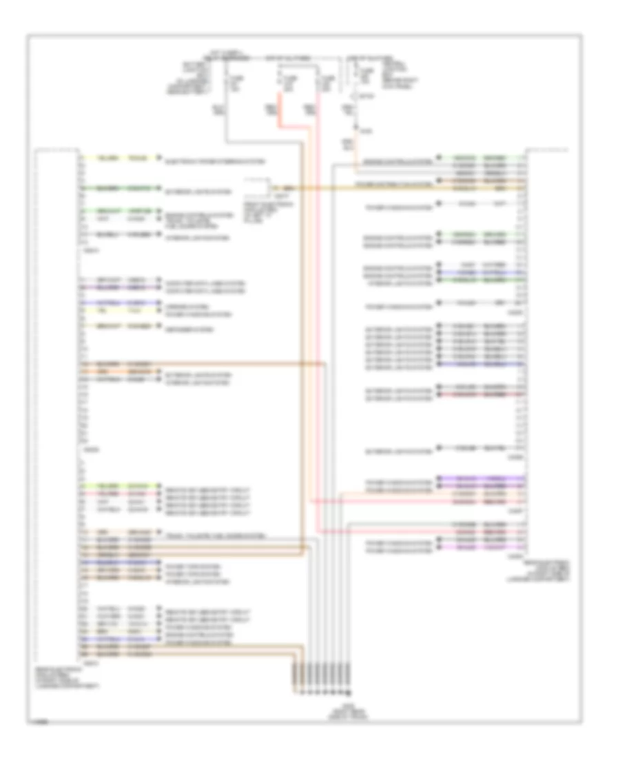
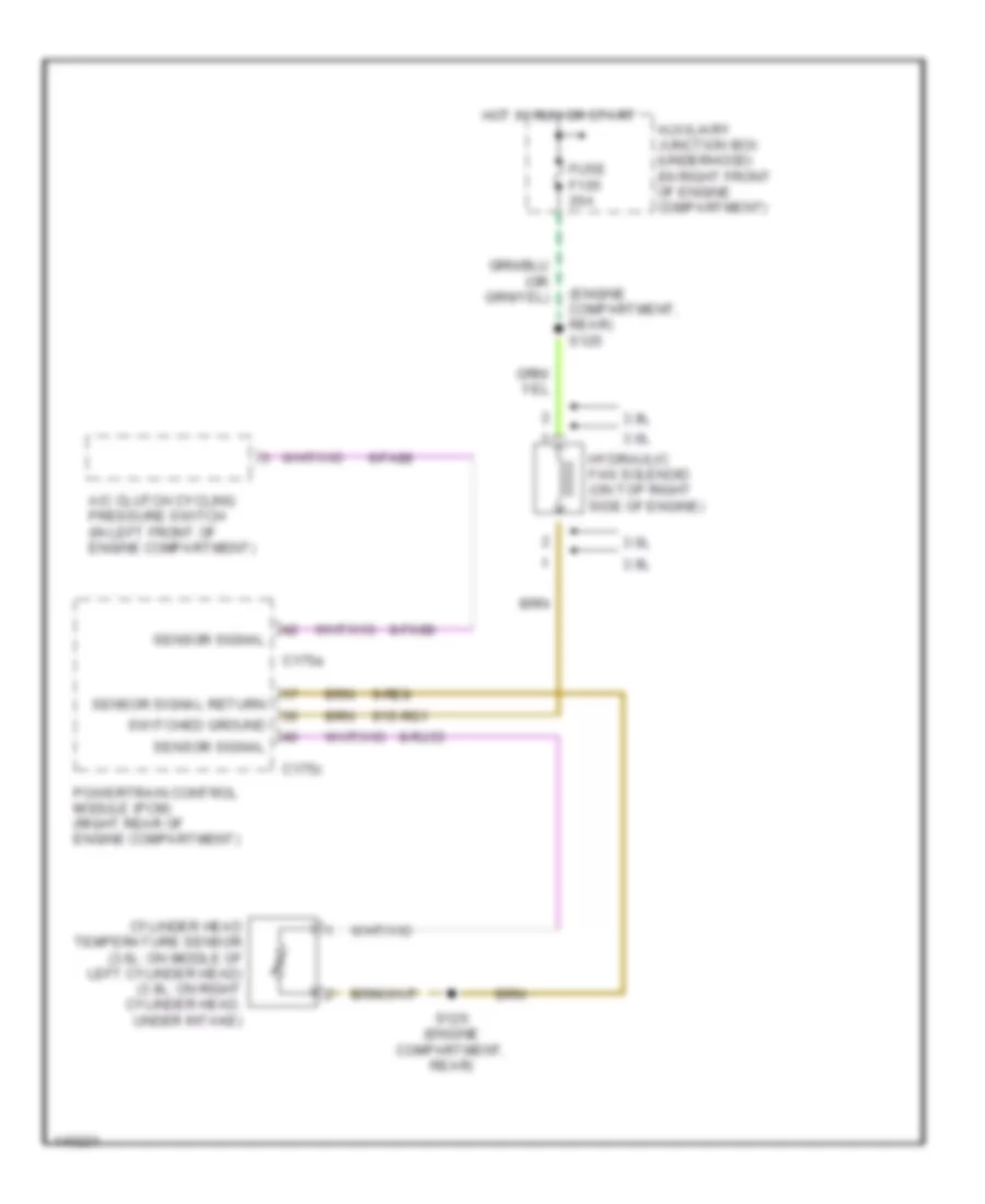
COOLING FAN
Cooling Fan Wiring Diagram for Lincoln LS 2001
 https://portal-diagnostov.com/license.html
Automotive Electricians Portal FZCO
Automotive Electricians Portal FZCO
https://portal-diagnostov.com/license.html
https://portal-diagnostov.com/license.html
Automotive Electricians Portal FZCO
Automotive Electricians Portal FZCOList of elements for Cooling Fan Wiring Diagram for Lincoln LS 2001:
- (engine compartment, rear) s125
- 3.0l
- 3.9l
- 8-fa88
- 8-rj33
- 9-re8
- 91s-rg1
- A/c clutch cycling pressure switch (in left front of engine compartment)
- Auxiliary junction box (underhood) (in right front of engine compartment)
- C175a
- C175c
- Cylinder head temperature sensor (3.0l: on middle of left cylinder head) (3.9l: on right cylinder head, under intake)
- Fuse f105 20a
- Hot in run or start
- Hydraulic fan solenoid (on top right side of engine)
- Powertrain control module (pcm) (right rear of engine compartment)
- S126 (engine compartment, rear)
- Sensor signal
- Sensor signal return
- Switched ground
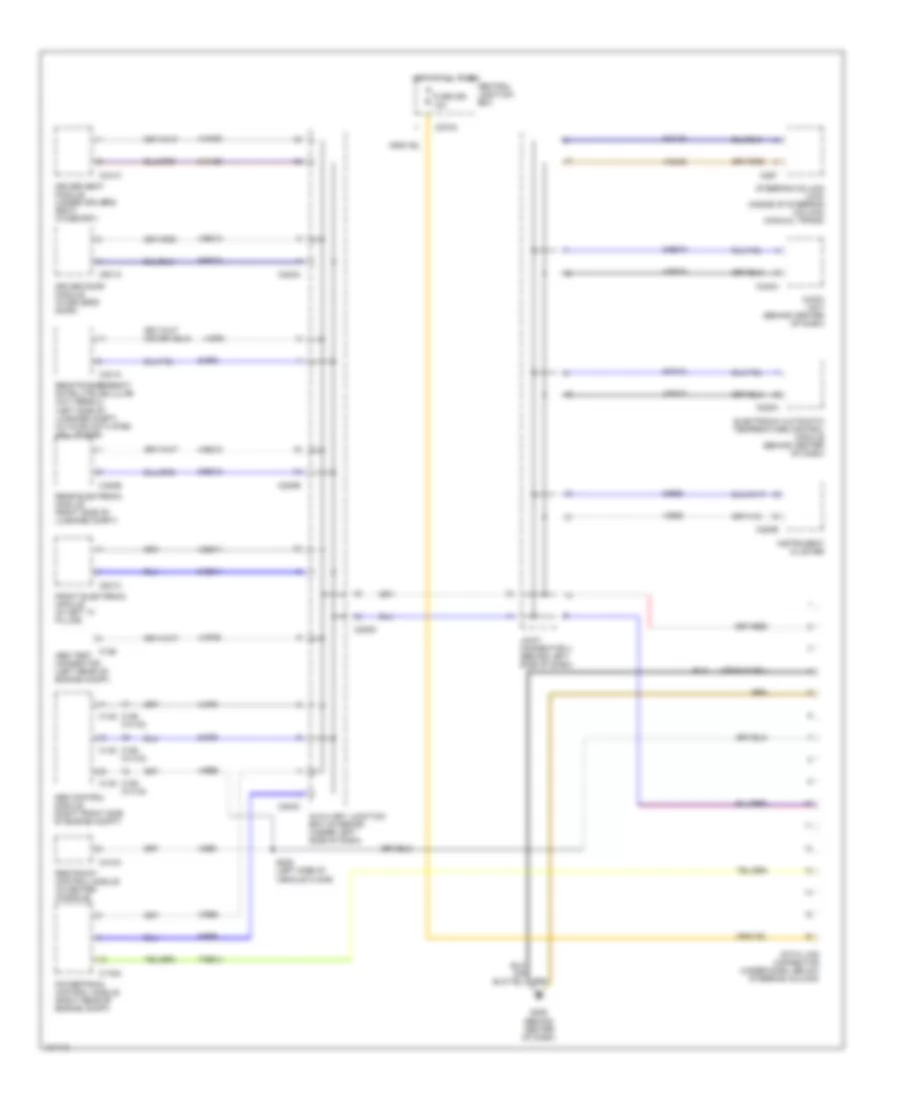
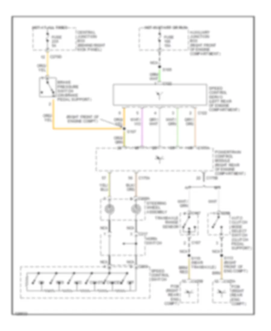
CRUISE CONTROL
Cruise Control Wiring Diagram for Lincoln LS 2001
 https://portal-diagnostov.com/license.html
Automotive Electricians Portal FZCO
Automotive Electricians Portal FZCO
https://portal-diagnostov.com/license.html
https://portal-diagnostov.com/license.html
Automotive Electricians Portal FZCO
Automotive Electricians Portal FZCOList of elements for Cruise Control Wiring Diagram for Lincoln LS 2001:
- (right front of engine compt)
- A/t
- Acc
- Auto clutch mode select switch (clutch pedal support)
- Auxiliary junction box (right front of engine compartment)
- Brake pressure switch (on brake pedal support)
- C122
- C167
- C175a
- C175b
- C203
- C217
- C218a
- C258
- C270d
- Cancel
- Central junction box (behind right kick panel)
- Coast
- Fuse 15a
- Fuse 5a
- Horn switch
- Hot at all times
- Hot in start or run
- M/t
- Nca
- Off
- Pcm (right rear eng compt)
- Powertrain control module (right rear of engine compartment)
- Res
- S105
- S107
- Speed control servo (left rear of engine compartment)
- Speed control switch
- Steering wheel assembly
- Transaxle range sensor
DEFOGGERS
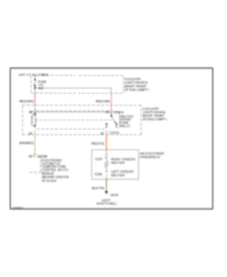
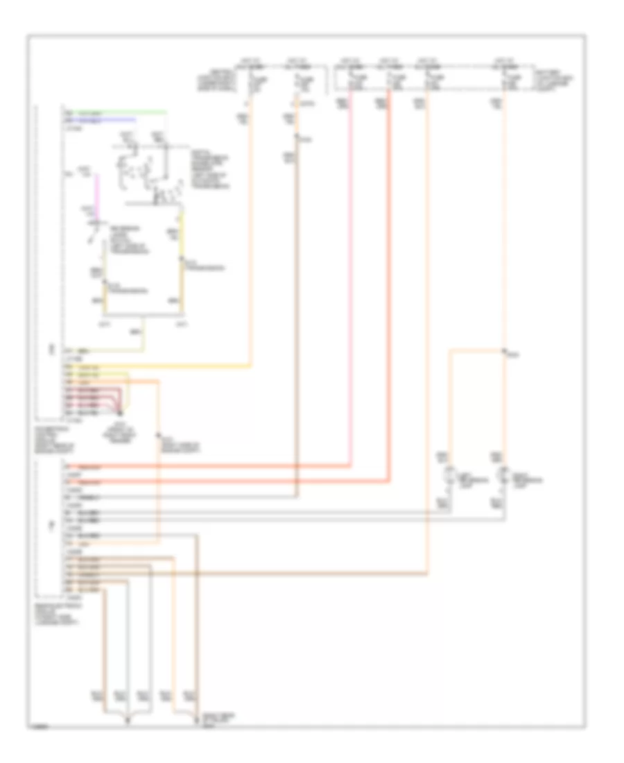
Front Defogger Wiring Diagram for Lincoln LS 2001
 https://portal-diagnostov.com/license.html
Automotive Electricians Portal FZCO
Automotive Electricians Portal FZCO
https://portal-diagnostov.com/license.html
https://portal-diagnostov.com/license.html
Automotive Electricians Portal FZCO
Automotive Electricians Portal FZCOList of elements for Front Defogger Wiring Diagram for Lincoln LS 2001:
- (left kick panel)
- Auxiliary junction box (right front of eng compt)
- C1014
- C228b
- C246
- C247
- Electronic automatic temperature control (eatc) module (behind center of dash)
- Fuse 30a
- G200
- Heated front windshield
- Heated wiper park relay
- Hot at all times
- Left window heater
- Right window heater
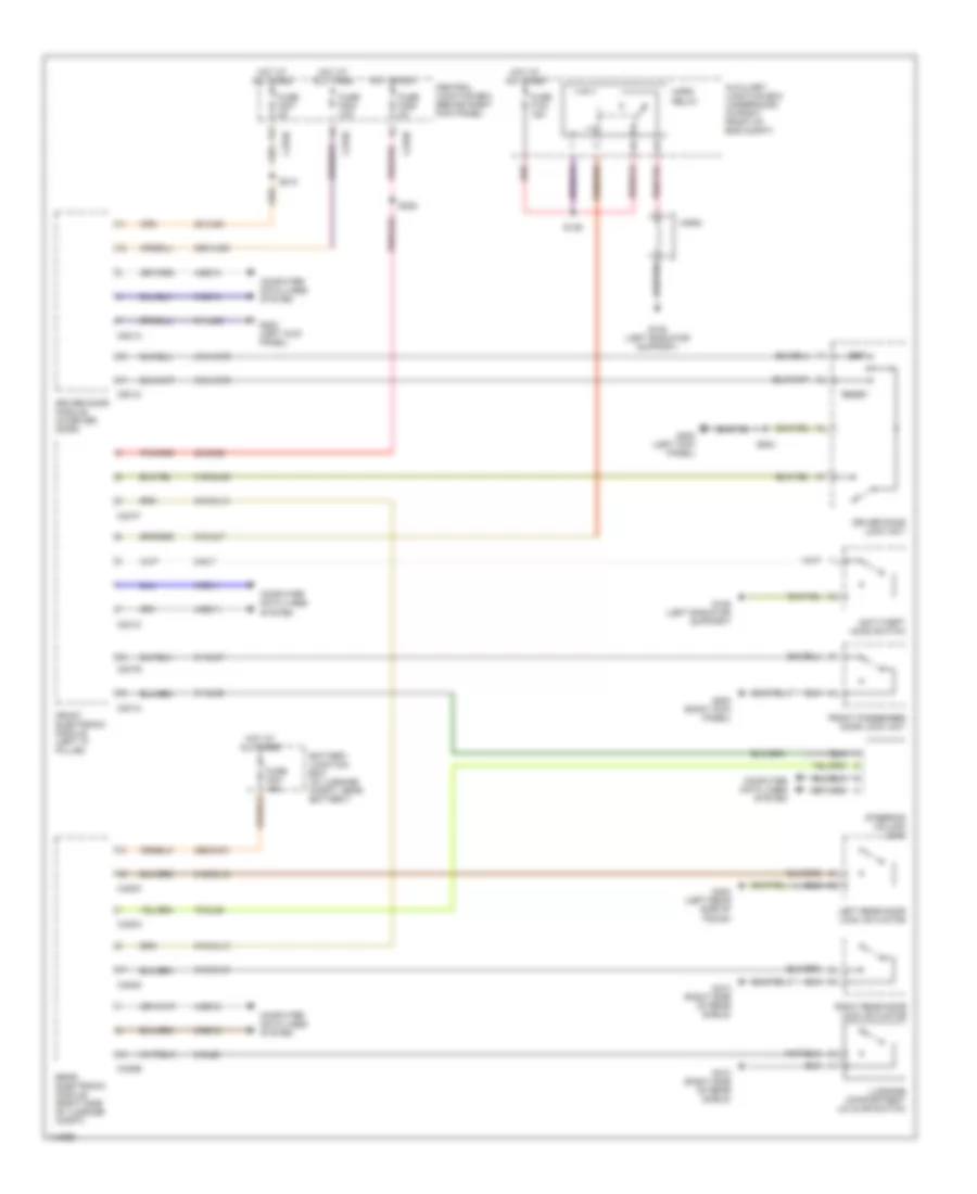
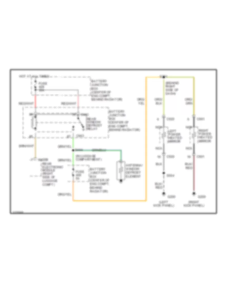
Rear Defogger & Heated Mirrors Wiring Diagram for Lincoln LS 2001
 https://portal-diagnostov.com/license.html
Automotive Electricians Portal FZCO
Automotive Electricians Portal FZCO
https://portal-diagnostov.com/license.html
https://portal-diagnostov.com/license.html
Automotive Electricians Portal FZCO
Automotive Electricians Portal FZCOList of elements for Rear Defogger & Heated Mirrors Wiring Diagram for Lincoln LS 2001:
- (behind right side of dash)
- (in luggage compartment)
- (left kick panel)
- (right kick panel)
- Antenna/ window defrost element
- Battery junction box (center of eng compt, behind radiator)
- C420b
- C443
- C520
- C601
- Fuse 30a
- Fuse 5a
- G200
- Hot at all times
- Left power heated mirror
- Nca
- Rear electronic module (right side of luggage compt)
- Rear window defrost relay
- Right power heated mirror
- S201
- S404
- S504
ELECTRONIC POWER STEERING
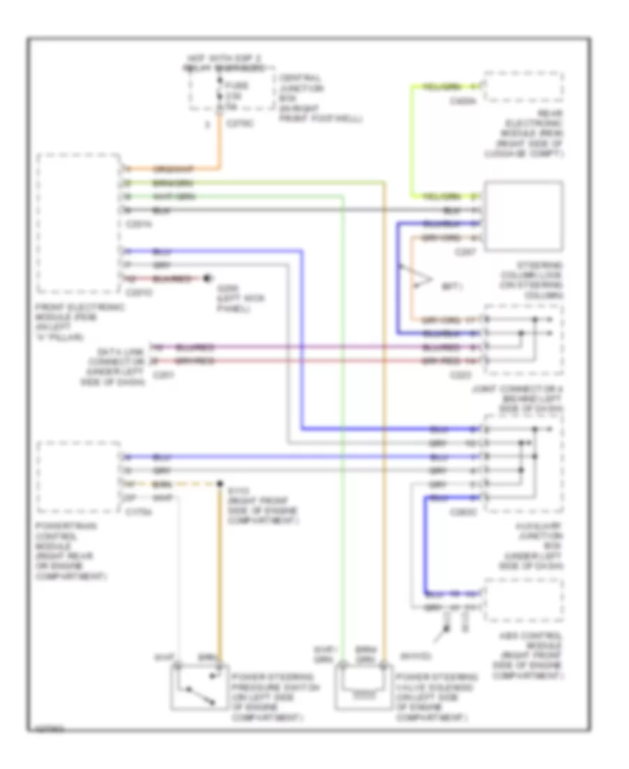
Electronic Power Steering Wiring Diagram for Lincoln LS 2001
 https://portal-diagnostov.com/license.html
Automotive Electricians Portal FZCO
Automotive Electricians Portal FZCO
https://portal-diagnostov.com/license.html
https://portal-diagnostov.com/license.html
Automotive Electricians Portal FZCO
Automotive Electricians Portal FZCOList of elements for Electronic Power Steering Wiring Diagram for Lincoln LS 2001:
- (m/t)
- (w/ivd)
- Abs control module (right front side of engine compartment)
- Auxiliary junction box (under left side of dash)
- C135
- C155
- C175a
- C201a
- C201c
- C223
- C267
- C270c
- C283c
- C420a
- Central junction box (in right front footwell)
- Data link connector (under left c251
- Front electronic module (fem) (in left "a" pillar)
- Fuse 5a
- G200 (left kick panel)
- Hot with ssp 2 relay energized
- Joint connector 4 (behind left side of dash)
- Power steering pressure switch (on left side of engine compartment)
- Power steering valve solenoid (on left side of engine compartment)
- Powertrain control module (right rear or engine compartment)
- Rear electronic module (rem) (right side of luggage compt)
- S113 (right front side of engine compartment)
- Side of dash)
- Steering column lock (on steering column)
ENGINE PERFORMANCE
3.0L
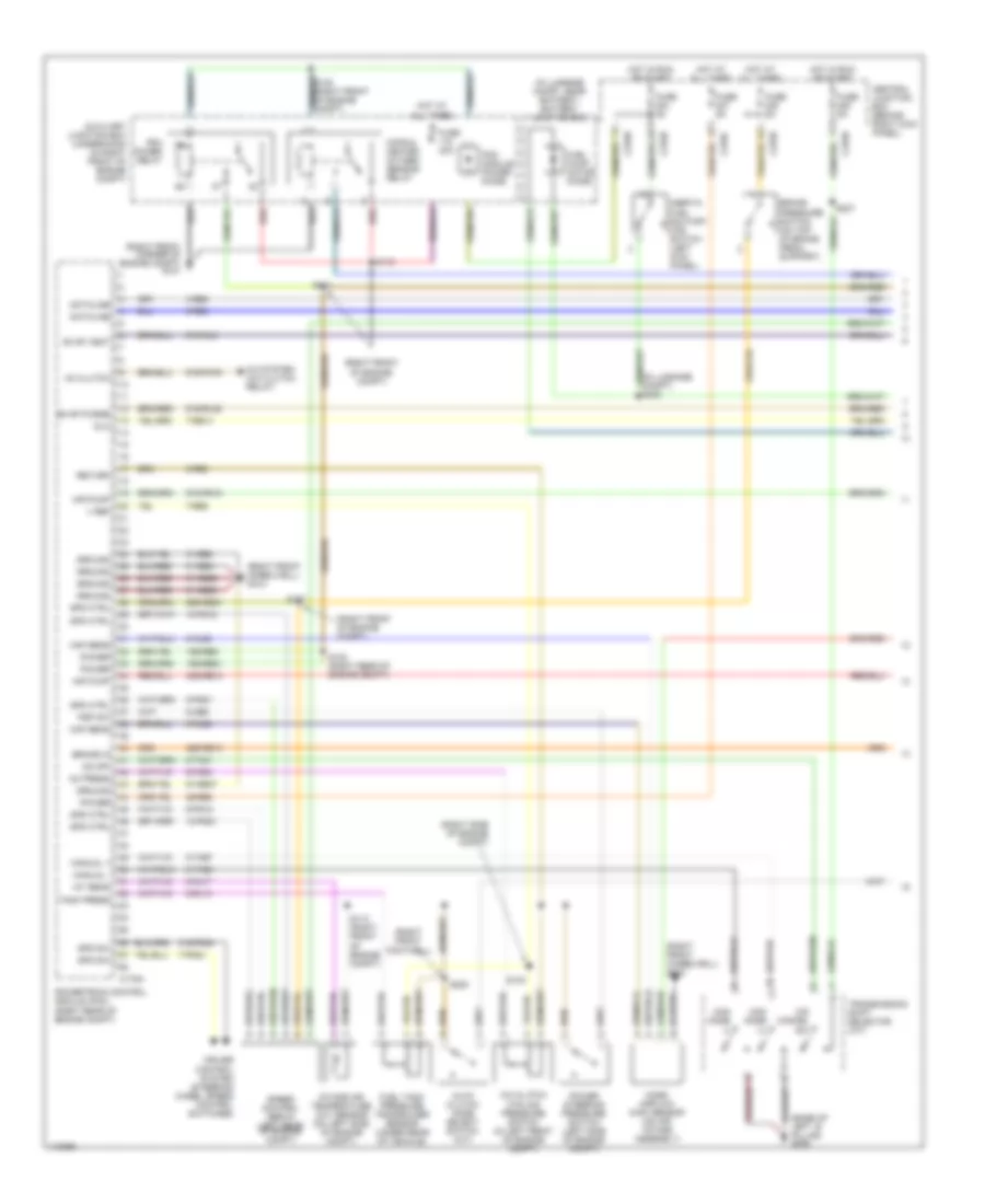
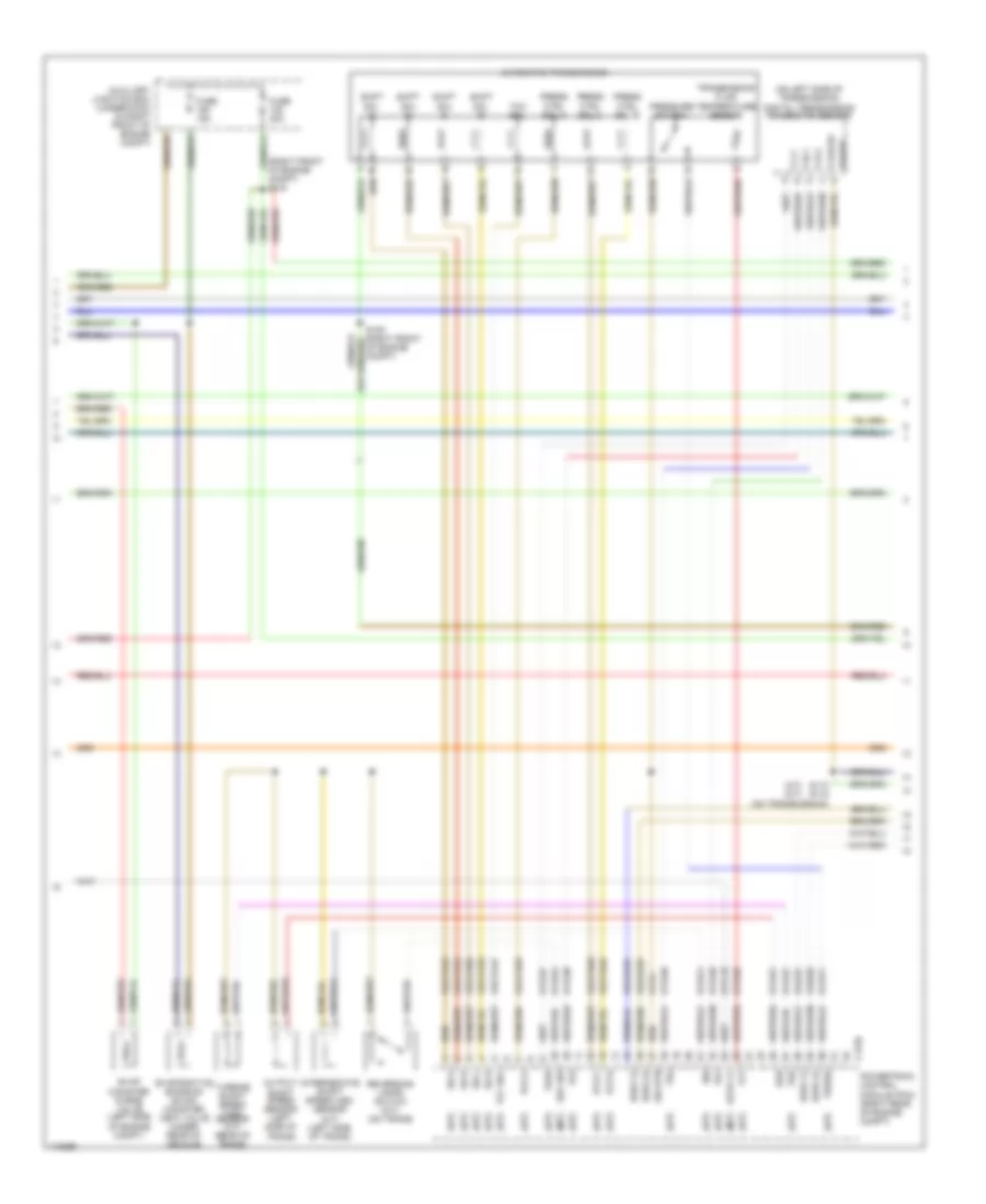
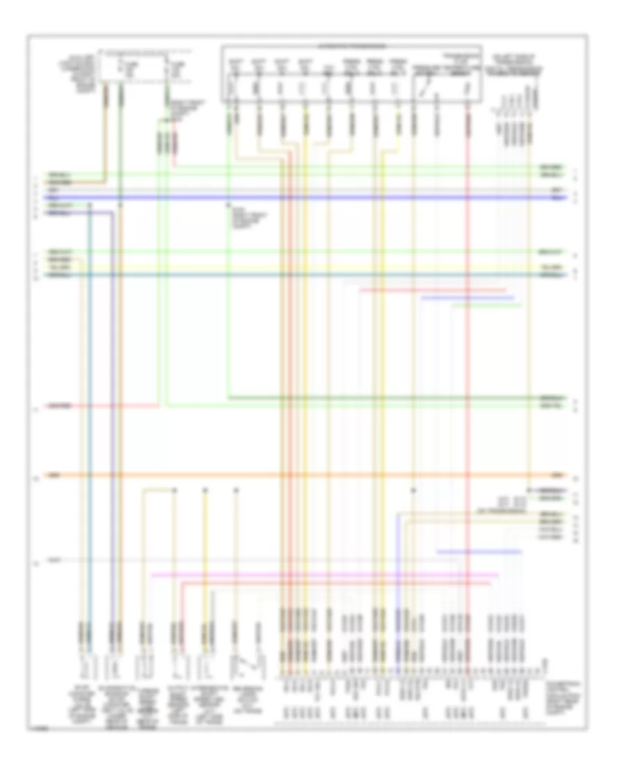
3.0L, Engine Performance Wiring Diagram (1 of 4) for Lincoln LS 2001
 https://portal-diagnostov.com/license.html
Automotive Electricians Portal FZCO
Automotive Electricians Portal FZCO
https://portal-diagnostov.com/license.html
https://portal-diagnostov.com/license.html
Automotive Electricians Portal FZCO
Automotive Electricians Portal FZCOList of elements for 3.0L, Engine Performance Wiring Diagram (1 of 4) for Lincoln LS 2001:
- (base of left b pillar) g308
- (in luggage compt) s403
- (in luggage compt, near battery) battery junction box
- (right front corner of engine compt) g101
- (right front footwell)
- (right front of engine compt)
- (right front wheelwell) g103
- (right side of engine compt)
- 10-pg12
- 10-pg21
- 15s-re21
- 15s-re8
- 29-re8
- 29s-re13
- 29s-re21
- 30s-re10
- 31-re21
- 31-re25
- 31-re26
- 31-re8
- 31s-pg24
- 4-re8
- 5-re8
- 7-pg24
- 7-re14
- 7-re8
- 8-ce6
- 8-fa88
- 8-pg12
- 8-pg21
- 8-rj13
- 8-rj17
- 8-rj22
- 8-ta21
- 8-ta67
- 8-ta68
- 9-re8
- 9-rj22
- 91-re27
- 91s-fa79
- 91s-rl25
- 91s-rl3
- 91s-rn10
- A/c clutch cycling pressure switch (in left front of engine compt)
- A/c system (a/c clutch relay)
- Ac clutch
- Ac press
- Air pump
- Auto clutch mode select switch (m/t)
- Auxiliary junction box (underhood) (in right front of engine compt)
- Brake in
- Brake pressure switch (on top of brake pedal support)
- C175a
- C270b
- C270c
- C270d
- Central junction box (behind right kick panel)
- Cops & heated oxygen sensor relay
- Cruise control system (steering wheel speed control switches)
- Dataline
- Dlc
- Evap purge
- Evap vent
- Fuel pump motor diode
- Fuel tank pressure transducer sensor (under rear of vehicle)
- Fuse 40a
- Fuse 5a
- Ground
- Hot at all times
- Hot in run or start
- Iat sens
- Inertia fuel shutoff (ifs) switch (left kick panel)
- Intake air temperature (iat) sensor (on left side of engine compt)
- Maf sens
- Man mode (+)
- Man mode (-)
- Manual +
- Manual -
- Mass airflow (maf) sensor (on air intake assembly)
- O/d cancel sw
- Od off
- Pcm module power diode
- Pcm power relay
- Power
- Power steering pressure switch (left side of engine compt)
- Powertrain control module (pcm) (right rear of engine compt)
- Psp sw
- Red
- Return
- S102 (right rear of engine compt)
- S103
- S107
- S111
- S112
- S113 (right front of engine compt)
- S207
- S220
- Spd ctrl
- Spd sw
- Speed control servo (left rear of engine compt)
- Tank press
- Transmission shift selector (a/t)
- V ref
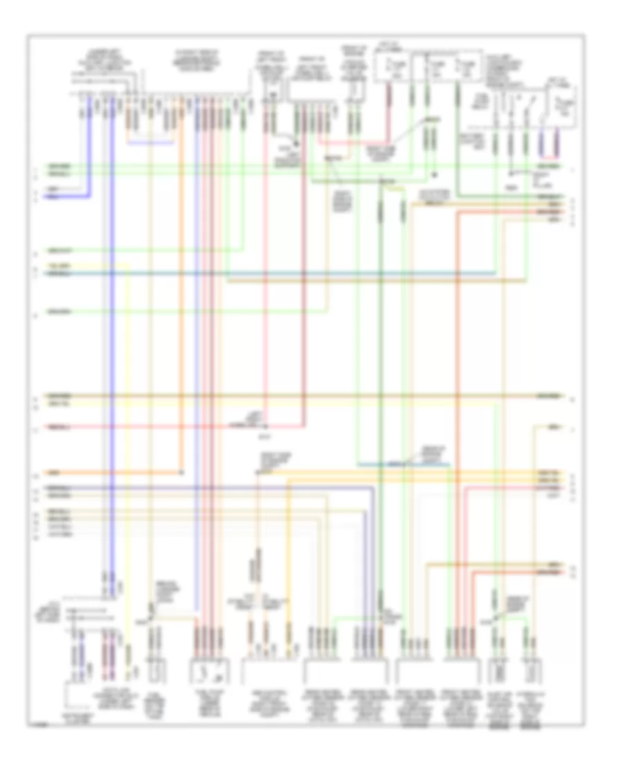
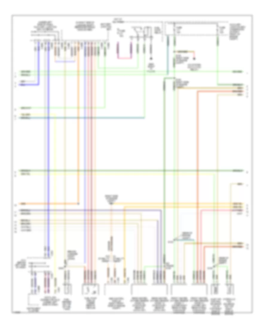
3.0L, Engine Performance Wiring Diagram (2 of 4) for Lincoln LS 2001
 https://portal-diagnostov.com/license.html
Automotive Electricians Portal FZCO
Automotive Electricians Portal FZCO
https://portal-diagnostov.com/license.html
https://portal-diagnostov.com/license.html
Automotive Electricians Portal FZCO
Automotive Electricians Portal FZCOList of elements for 3.0L, Engine Performance Wiring Diagram (2 of 4) for Lincoln LS 2001:
- (a/t)
- (a/t) (m/t)
- (m/t)
- (on left side of transmission) digital transmission range (dtr) sensor
- (right front of engine compt) s104
- 8-rj25
- 8-rs26
- 8-ta26
- 8-ta27
- 8-ta37
- 8-ta38
- 8-ta39
- 8-ta40
- 8-ta51
- 8-ta54
- 8-ta71
- 8-ta74
- 8-tc18
- 9-ta1
- 91s-rj25
- 91s-rj26
- 91s-ta23
- 91s-ta24
- 91s-ta47
- 91s-ta63
- 91s-ta64
- 91s-ta65
- 91s-ta69
- 91s-ta70
- Auto cl
- Automatic transmission
- Auxiliary junction box (underhood) (in right front of engine compt)
- C175b
- Evap canister purge valve (left side of engine compt)
- Evaporative emission (evap) canister vent valve (under rear of vehicle)
- Fuse 15a
- Fuse 20a
- H2os 12
- H2os 22
- Intermediate shaft speed (iss) sensor (a/t) (left side of trans)
- Iss
- Oss
- Output shaft speed sensor (left side of trans)
- P,2,1
- P,n,1
- P,r,2
- P,r,n,3/4
- Pcs a
- Pcs b
- Pcs c
- Power
- Powertrain control module (pcm) (right rear of engine compt)
- Press
- Press ctrl sol a
- Press ctrl sol b
- Press ctrl sol c
- Pressure switch
- Rev sw
- Reversing lamps switch (m/t) (on trans)
- S105 (right front of engine compt)
- S110 s116 (on transmission)
- Shift sol a
- Shift sol b
- Shift sol c
- Shift sol d
- Sig rtn
- Ss a
- Ss b
- Ss c
- Ss d
- Tcc sol
- Tft
- Tr1
- Tr2
- Tr3a
- Tr4
- Transmission fluid temperature sensor
- Tss
- Turbine shaft speed (tss) sensor (a/t) (rear of trans)
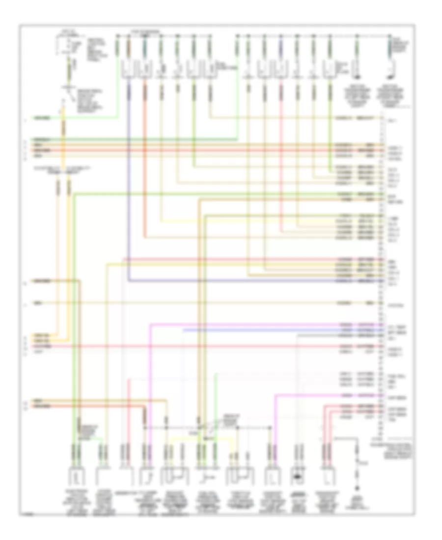
3.0L, Engine Performance Wiring Diagram (3 of 4) for Lincoln LS 2001
 https://portal-diagnostov.com/license.html
Automotive Electricians Portal FZCO
Automotive Electricians Portal FZCO
https://portal-diagnostov.com/license.html
https://portal-diagnostov.com/license.html
Automotive Electricians Portal FZCO
Automotive Electricians Portal FZCOList of elements for 3.0L, Engine Performance Wiring Diagram (3 of 4) for Lincoln LS 2001:
- (behind luggage compt lining)
- (front of
- (front of engine)
- (front of left front
- (in right side of luggage compt) rear electronic module (rem)
- (left front wheelwell)
- (left radiator support)
- (rear of engine compt)
- (right "c" pillar)
- (right side of engine compt)
- (right side of engine compt) s101
- (under left side of dash) auxiliary junction box (interior)
- A/c system (a/c clutch relay)
- Abs control module (right front side of engine compt)
- Auxiliary junction box (underhood) (in right front of engine compt)
- Battery junction box
- C135
- C155
- C159
- C220b
- C223
- C251
- C283b
- C283c
- C283d
- C420a
- C420b
- C420c
- C420d
- Data link connector (dlc) (under left side of dash)
- Front heated oxygen sensor (ho2s) 11 (lower right rear of eng, in exhaust manifold)
- Front heated oxygen sensor (ho2s) 21 (lower left rear of eng, in exhaust manifold)
- Fuel pump module (under rear of vehicle)
- Fuel pump relay
- Fuel sender (on top of fuel tank)
- Fuse 10a
- Fuse 15a
- Fuse 20a
- G108
- G905
- Hot at all times
- Hydraulic fan solenoid (on top right side of engine)
- Inlet air control solenoid valve (top right side of engine)
- Instrument cluster
- J/c 4 (behind left side of dash)
- Left front wheelwell) air pump relay
- Rear heated oxygen sensor (ho2s) 12 (in exhaust, rear of catalyst)
- Rear heated oxygen sensor (ho2s) 22 (in exhaust, rear of catalyst)
- S106
- S125
- S132
- S135
- S147
- S148
- S402
- Trans) s109
- Vacuum diverter valve solenoid
- W/ stability assist
- W/o stability assist
- Wheelwell) air pump motor
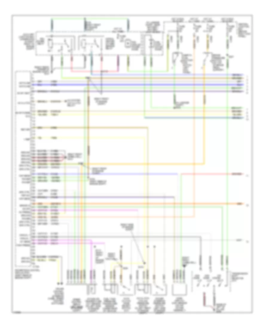
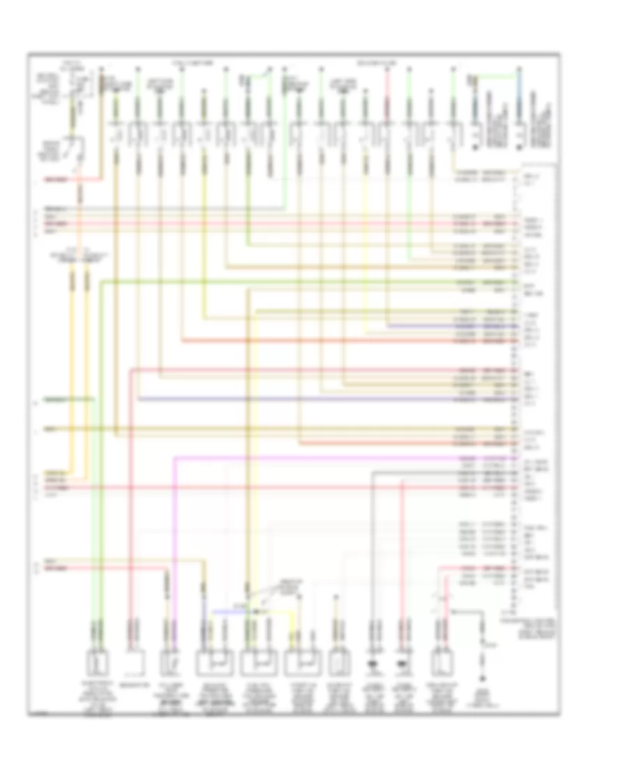
3.0L, Engine Performance Wiring Diagram (4 of 4) for Lincoln LS 2001
 https://portal-diagnostov.com/license.html
Automotive Electricians Portal FZCO
Automotive Electricians Portal FZCO
https://portal-diagnostov.com/license.html
https://portal-diagnostov.com/license.html
Automotive Electricians Portal FZCO
Automotive Electricians Portal FZCOList of elements for 3.0L, Engine Performance Wiring Diagram (4 of 4) for Lincoln LS 2001:
- (on top right side of engine)
- (rear of engine compt)
- (rear of engine compt) s156
- (top of engine) s128
- 10-ba25
- 10-rj18
- 10-rj4
- 7-rn11
- 8-ba25
- 8-rj11
- 8-rj15
- 8-rj18
- 8-rj28
- 8-rj3
- 8-rj33
- 8-rj4
- 8-rj7
- 8-rs14
- 9-re8
- 91s-rg1
- 91s-rj15
- 91s-rl10
- 91s-rl11
- 91s-rl12
- 91s-rl13
- 91s-rl14
- 91s-rl15
- 91s-rl19
- 91s-rl20
- 91s-rl7
- 91s-rr10
- 91s-rr5
- 91s-rr6
- 91s-rr7
- 91s-rr8
- 91s-rr9
- 91s-rs14
- Brake pedal position switch (on top of brake pedal support)
- C175c
- C270d
- Camshaft position (cmp) sensor (on top left side of engine compt)
- Central junction box (behind right kick panel)
- Ckp sens
- Cmp sens
- Coil 1
- Coil 2
- Coil 3
- Coil 4
- Coil 5
- Coil 6
- Coils on plugs
- Crankshaft position sensor (lower left front of engine)
- Cyl temp
- Cylinder head temperature sensor (on middle of left cyl head)
- Electronic vacuum regulator (evr) solenoid valve (left rear of engine)
- Ept sens
- Evr
- Exhaust pressure transducer (ept) sensor (left rear side of engine compt)
- Fuel injectors
- Fuel rail
- Fuel rail pressure transducer sensor (on left side of engine)
- Fuse 5a
- G103 (right front wheelwell)
- Gen
- Generator
- Ho2s 11
- Ho2s 21
- Hot at all times
- Hyd fan
- Iac sol
- Ignition transformer capacitor 1 (in left rear of engine compt)
- Ignition transformer capacitor 2 (in right rear of engine compt)
- Imrc
- Inj 1
- Inj 2
- Inj 3
- Inj 4
- Inj 5
- Inj 6
- Intake manifold runner control module (right rear eng compt)
- Knock sensor 1
- Ks 1
- Nca
- Powertrain control module (pcm) (right rear of engine compt)
- Return
- S124
- S126
- S127
- S151 (rear of engine compt)
- Throttle position (tps) sensor (on right side of engine)
- Tps
- V ref
- W/ stability assist
- W/o stability assist
3.9L
3.9L, Engine Performance Wiring Diagram (1 of 4) for Lincoln LS 2001
 https://portal-diagnostov.com/license.html
Automotive Electricians Portal FZCO
Automotive Electricians Portal FZCO
https://portal-diagnostov.com/license.html
https://portal-diagnostov.com/license.html
Automotive Electricians Portal FZCO
Automotive Electricians Portal FZCOList of elements for 3.9L, Engine Performance Wiring Diagram (1 of 4) for Lincoln LS 2001:
- (base of left "b" pillar) g308
- (in luggage compt) s403
- (in luggage compt, near battery) battery junction box
- (right front corner of engine compt) g101
- (right front footwell)
- (right front of engine compt)
- (right front wheelwell) g103
- (right side of engine compt)
- 10-pg12
- 10-pg21
- 15s-re21
- 15s-re8
- 29-re8
- 29s-re13
- 29s-re21
- 31-re21
- 31-re25
- 31-re26
- 31-re8
- 31s-pg24
- 4-re8
- 5-re8
- 7-pg24
- 7-re14
- 7-re8
- 8-ce6
- 8-fa88
- 8-pg12
- 8-pg21
- 8-rj13
- 8-rj17
- 8-rj22
- 8-ta21
- 8-ta67
- 8-ta68
- 9-re8
- 9-rj22
- 91-re27
- 91s-fa79
- 91s-rl25
- 91s-rl3
- A/c clutch cycling pressure switch (in left front of engine compt)
- A/c system (a/c clutch relay)
- Ac clutch
- Ac press
- Auto clutch mode select switch (m/t)
- Auxiliary junction box (underhood) (in right front of engine compt)
- Brake in
- Brake pressure switch (on top of brake pedal support)
- C175a
- C270b
- C270c
- C270d
- Central junction box (behind right kick panel)
- Cops & heated oxygen sensor relay
- Cruise control system (steering wheel speed control switches)
- Dataline
- Dlc
- Evap purge
- Evap vent
- Fuel pump motor diode
- Fuel tank pressure transducer sensor (under rear of vehicle)
- Fuse 40a
- Fuse 5a
- Ground
- Hot at all times
- Hot in run or start
- Iat sens
- Inertia fuel shutoff (ifs) switch (left kick panel)
- Intake air temperature (iat) sensor (on left side of engine compt)
- Maf sens
- Man mode (+)
- Man mode (-)
- Manual +
- Manual -
- Mass airflow (maf) sensor (on air intake assembly)
- O/d cancel sw
- Od off
- Pcm module power diode
- Pcm power relay
- Power
- Power steering pressure switch (left side of engine compt)
- Powertrain control module (pcm) (right rear of engine compt)
- Psp sw
- Red
- Return
- S102 (right rear of engine compt)
- S103
- S107
- S111
- S112
- S113 (right front of engine compt)
- S207
- S220
- Spd ctrl
- Spd sw
- Speed control servo (left rear of engine compt)
- Tank press
- Transmission shift selector (a/t)
- V ref
3.9L, Engine Performance Wiring Diagram (2 of 4) for Lincoln LS 2001
 https://portal-diagnostov.com/license.html
Automotive Electricians Portal FZCO
Automotive Electricians Portal FZCO
https://portal-diagnostov.com/license.html
https://portal-diagnostov.com/license.html
Automotive Electricians Portal FZCO
Automotive Electricians Portal FZCOList of elements for 3.9L, Engine Performance Wiring Diagram (2 of 4) for Lincoln LS 2001:
- (a/t)
- (a/t) (m/t)
- (m/t)
- (on left side of transmission) digital transmission range (dtr) sensor
- (right front of engine compt) s104
- 8-rj25
- 8-rs26
- 8-ta26
- 8-ta27
- 8-ta37
- 8-ta38
- 8-ta39
- 8-ta40
- 8-ta51
- 8-ta54
- 8-ta71
- 8-ta74
- 8-tc18
- 9-ta1
- 91s-rj25
- 91s-rj26
- 91s-ta23
- 91s-ta24
- 91s-ta47
- 91s-ta63
- 91s-ta64
- 91s-ta65
- 91s-ta69
- 91s-ta70
- Auto cl
- Automatic transmission
- Auxiliary junction box (underhood) (in right front of engine compt)
- C175b
- Evap canister purge valve (left side of engine compt)
- Evaporative emission (evap) canister vent valve (under rear of vehicle)
- Fuse 15a
- Fuse 20a
- H2os 12
- H2os 22
- Intermediate shaft speed (iss) sensor (a/t) (left side of trans)
- Iss
- Oss
- Output shaft speed sensor (left side of trans)
- P,2,1
- P,n,1
- P,r,2
- P,r,n,3/4
- Pcs a
- Pcs b
- Pcs c
- Power
- Powertrain control module (pcm) (right rear of engine compt)
- Press
- Press ctrl sol a
- Press ctrl sol b
- Press ctrl sol c
- Pressure switch
- Rev sw
- Reversing lamps switch (m/t) (on trans)
- S105 (right front of engine compt)
- S110 s116 (on transmission)
- Shift sol a
- Shift sol b
- Shift sol c
- Shift sol d
- Sig rtn
- Ss a
- Ss b
- Ss c
- Ss d
- Tcc sol
- Tft
- Tr1
- Tr2
- Tr3a
- Tr4
- Transmission fluid temperature sensor
- Tss
- Turbine shaft speed (tss) sensor (a/t) (rear of trans)
3.9L, Engine Performance Wiring Diagram (3 of 4) for Lincoln LS 2001
 https://portal-diagnostov.com/license.html
Automotive Electricians Portal FZCO
Automotive Electricians Portal FZCO
https://portal-diagnostov.com/license.html
https://portal-diagnostov.com/license.html
Automotive Electricians Portal FZCO
Automotive Electricians Portal FZCOList of elements for 3.9L, Engine Performance Wiring Diagram (3 of 4) for Lincoln LS 2001:
- (behind luggage compt lining)
- (in right side of luggage compt) rear electronic module (rem)
- (rear of engine compt)
- (right side of engine compt) s101
- (under left side of dash) auxiliary junction box (interior)
- A/c system (a/c clutch relay)
- Abs control module (right front side of engine compt)
- Auxiliary junction box (underhood) (in right front of engine compt)
- Battery junction box
- C135
- C155
- C220b
- C223
- C251
- C283b
- C283c
- C283d
- C420a
- C420b
- C420c
- C420d
- Data link connector (dlc) (under left side of dash)
- Front heated oxygen sensor (ho2s) 11 (lower right rear of eng, in exhaust manifold)
- Front heated oxygen sensor (ho2s) 21 (lower left rear of eng, in exhaust manifold)
- Fuel pump module (under rear of vehicle)
- Fuel pump relay
- Fuel sender (on top of fuel tank)
- Fuse 10a
- Fuse 15a
- G905 (right "c" pillar)
- Hot at all times
- Hydraulic fan solenoid (on top right side of engine)
- Inlet air control solenoid valve (top right side of engine)
- Instrument cluster
- J/c 4 (behind left side of dash)
- Rear heated oxygen sensor (ho2s) 12 (in exhaust, rear of catalyst)
- Rear heated oxygen sensor (ho2s) 22 (in exhaust, rear of catalyst)
- S106 (right side of engine compt)
- S125
- S132
- S135 (right side of engine compt)
- S402
- Trans) s109
- W/ stability assist
- W/o stability assist
3.9L, Engine Performance Wiring Diagram (4 of 4) for Lincoln LS 2001
 https://portal-diagnostov.com/license.html
Automotive Electricians Portal FZCO
Automotive Electricians Portal FZCO
https://portal-diagnostov.com/license.html
https://portal-diagnostov.com/license.html
Automotive Electricians Portal FZCO
Automotive Electricians Portal FZCOList of elements for 3.9L, Engine Performance Wiring Diagram (4 of 4) for Lincoln LS 2001:
- (in left rear of engine compt)
- (left side of engine) s129
- (left side of engine) s130
- (on top left side of engine)
- (on top right side of engine)
- (rear of engine compt)
- 10-ba25
- 10-rj18
- 10-rj19
- 10-rj4
- 7-rn11
- 8-ba25
- 8-rj11
- 8-rj15
- 8-rj18
- 8-rj19
- 8-rj28
- 8-rj3
- 8-rj33
- 8-rj4
- 8-rj7
- 8-rs14
- 9-re8
- 91-rr5
- 91s-rg1
- 91s-rj15
- 91s-rl10
- 91s-rl11
- 91s-rl12
- 91s-rl13
- 91s-rl14
- 91s-rl15
- 91s-rl16
- 91s-rl17
- 91s-rl19
- 91s-rl7
- 91s-rr10
- 91s-rr11
- 91s-rr12
- 91s-rr6
- 91s-rr7
- 91s-rr8
- 91s-rr9
- 91s-rs14
- Brake pedal position switch
- C175c
- C270d
- Camshaft position sensor (on top left rear of cyl head)
- Capacitor 1 ignition transformer
- Capacitor 2 ignition transformer
- Central junction box (behind right kick panel)
- Ckp sens
- Cmp sens
- Coil 1
- Coil 2
- Coil 3
- Coil 4
- Coil 5
- Coil 6
- Coil 7
- Coil 8
- Coils on plugs
- Crankshaft position sensor (lower left front of engine)
- Cyl temp
- Cylinder head temperature sensor (on right cyl head, under intake)
- Electronic vacuum regulator (evr) solenoid valve (left rear of engine)
- Ept sens
- Evr
- Exhaust pressure transducer (ept) sensor (left rear side of engine compt)
- Fuel injectors
- Fuel rail
- Fuel rail pressure transducer sensor (on left side of engine)
- Fuse 15a
- G103 (right front wheelwell)
- Gen
- Generator
- Ho2s 11
- Ho2s 21
- Hot at all times
- Hyd fan
- Iac sol
- Inj 1
- Inj 2
- Inj 3
- Inj 4
- Inj 5
- Inj 6
- Inj 7
- Inj 8
- Knock sensor 1
- Knock sensor 2
- Ks 1
- Ks 2
- Nca
- Of engine compt) (in right rear
- Powertrain control module (pcm) (right rear of engine compt)
- Return
- S124
- S126
- S127
- S131 (rear of engine)
- S150 (right side of engine)
- Throttle position sensor (on right side of engine)
- Tps
- V ref
- W/ stability assist
- W/o stability assist
EXTERIOR LIGHTS
Backup Lamps Wiring Diagram for Lincoln LS 2001
 https://portal-diagnostov.com/license.html
Automotive Electricians Portal FZCO
Automotive Electricians Portal FZCO
https://portal-diagnostov.com/license.html
https://portal-diagnostov.com/license.html
Automotive Electricians Portal FZCO
Automotive Electricians Portal FZCOList of elements for Backup Lamps Wiring Diagram for Lincoln LS 2001:
- (a/t)
- (m/t)
- (right rear of trunk) g405
- Battery junction box (in luggage compt)
- C175a
- C175b
- C270c
- C420b
- C420c
- C420d
- C420e
- C420f
- C420g
- Central junction box (under right side of dash)
- Digital transmission range (dtr) sensor (left side of automatic transmission)
- Fuse 10a
- Fuse 15a
- Fuse 20a
- Fuse 5a
- G101 (front of right front fender)
- Hot at all times
- Left reversing lamp
- Powertrain control module (right rear of engine compt)
- Rear electronic module (in right side luggage compt)
- Reversing lamps switch (left side of transmission)
- Right reversing lamp
- S101 (right side of engine compt)
- S110 (transmission)
- S116 (transmission)
- S153
- S423
Exterior Lamps Wiring Diagram (1 of 2) for Lincoln LS 2001
 https://portal-diagnostov.com/license.html
Automotive Electricians Portal FZCO
Automotive Electricians Portal FZCO
https://portal-diagnostov.com/license.html
https://portal-diagnostov.com/license.html
Automotive Electricians Portal FZCO
Automotive Electricians Portal FZCOList of elements for Exterior Lamps Wiring Diagram (1 of 2) for Lincoln LS 2001:
- (power distribution)
- (w/ ivd)
- (w/o ivd)
- 29-dk20
- 31-dk20
- 31-dk20a
- 31-dk20b
- 31-dk20c
- 31-dk20d
- 31s-lf16
- 31s-lf17
- 31s-lf7
- 31s-lf8
- 31s-lg11
- 31s-lg18
- 4-eg11
- 4-eg8
- 5-eg11
- 5-eg8
- 8-le21
- 8-lg43
- 9-le29
- 9-lg43
- Abs control module (right front engine compt)
- Auxiliary junction box (in luggage compt)
- Brake pedal position (bpp) switch (on brake pedal support)
- C155
- C201a
- C201b
- C201c
- C202
- C205
- C217
- C220b
- C220c
- C270b
- C270c
- C270d
- C400
- Central junction box (behind right kick panel)
- Computer data lines system
- Front electronic module (in left kick "a" pillar)
- Fuse 10a
- Fuse 5a
- Fuse f439 60a
- G202 (behind left side of dash)
- Hazard
- Head
- Hot at all times
- Instrument cluster
- Left
- Left front park/ turn lamp
- Left front side marker lamp
- Main light switch
- Multi- function switch
- Off
- Park
- Right
- Right front park/ turn lamp
- Right front side marker lamp
- S101 (right side of engine compt)
- S108
- S114
- S153 (right rear of engine compt)
- S413 (in luggage compt)
- Steering wheel assembly
- Trailer exterior lamp relay (rear of vehicle)
Exterior Lamps Wiring Diagram (2 of 2) for Lincoln LS 2001
 https://portal-diagnostov.com/license.html
Automotive Electricians Portal FZCO
Automotive Electricians Portal FZCO
https://portal-diagnostov.com/license.html
https://portal-diagnostov.com/license.html
Automotive Electricians Portal FZCO
Automotive Electricians Portal FZCOList of elements for Exterior Lamps Wiring Diagram (2 of 2) for Lincoln LS 2001:
- (in decklid) s408
- (in luggage compt)
- (in luggage compt) (w/ trailer tow package only)
- (trailer tow connector)
- (w/ trailer tow)
- (w/o trailer tow)
- 29-dk31
- 29s-dk30
- 30s-nd16a
- 30s-nd16b
- 31-dk30d
- 31-dk30e
- 31-dk30f
- 31-dk30g
- 31-dk30h
- 31-nd16
- 31s-lf2
- 31s-lf4a
- 31s-lg12a
- 31s-lg14
- 31s-lg19a
- 31s-lg21a
- 31s-lg6
- 31s-nd18
- 31s-nd19
- 31s-nd21
- 31s-nd22
- 87-nd29
- 88-nd28
- 96-nd31
- Battery junction box (in luggage compt)
- C420a
- C420b
- C420c
- C420d
- C420e
- C425
- C439
- Fuse 10a
- Fuse 5a
- G405 (right rear side of trunk)
- High mounted stoplamp
- Hot at all times
- Left license plate lamp
- Left rear lamp assembly
- Left rear turning lamp
- Left tail- lamp
- Rear electronic module (right side luggage compt)
- Right license plate lamp
- Right rear lamp assembly
- Right rear turning lamp
- Right tail- lamp
- S401 (left rear side of vehicle)
- S407 (in decklid)
- S415
- S417 (in luggage compt) (w/ trailer tow package only)
- S418 (in luggage compt) (w/ trailer tow package only)
- S419
- S420
- S422
- S423
- S427
- S428
- S431 (in luggage compt)
- S432
- S433 (in luggage compt) (w/ trailer tow package only)
- Trailer tow control unit (rear center of luggage compt)
- Vehicle)
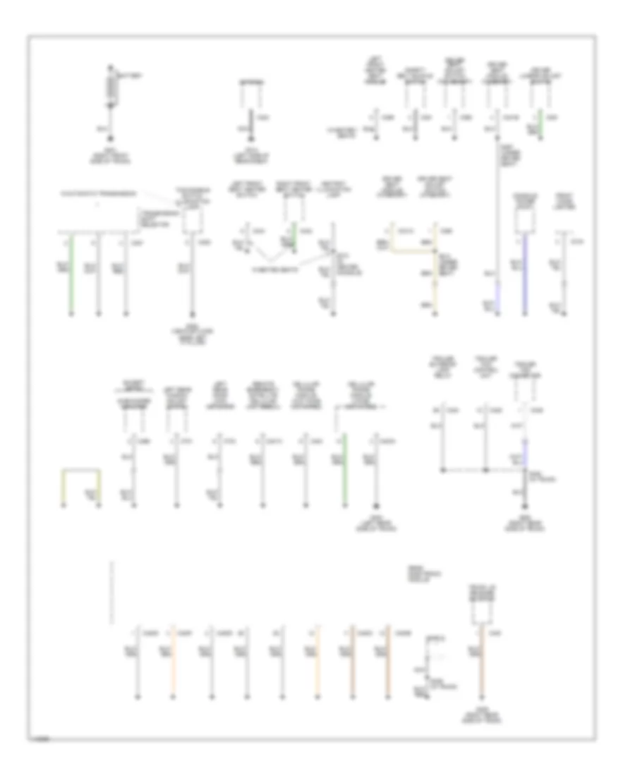
GROUND DISTRIBUTION
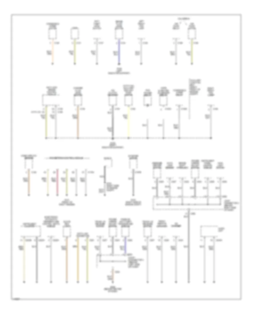
Ground Distribution Wiring Diagram (1 of 3) for Lincoln LS 2001
 https://portal-diagnostov.com/license.html
Automotive Electricians Portal FZCO
Automotive Electricians Portal FZCO
https://portal-diagnostov.com/license.html
https://portal-diagnostov.com/license.html
Automotive Electricians Portal FZCO
Automotive Electricians Portal FZCOList of elements for Ground Distribution Wiring Diagram (1 of 3) for Lincoln LS 2001:
- (with 3.9l) auxiliary coolant pump motor
- A/c clutch solenoid
- Air pump motor
- Air pump relay
- Anti- theft hood switch
- Anti-lock brake control module
- Audio unit
- Auto lamp sensor
- Auxiliary junction box (right front of engine compt)
- Brake fluid level switch
- Brake shift interlock
- C100
- C1003
- C1009
- C124
- C125
- C127
- C128
- C131
- C135
- C138
- C152
- C155
- C158
- C159
- C162
- C163
- C175a
- C197b
- C204
- C205
- C206
- C207
- C220a
- C220b
- C224
- C225
- C228a
- C240c
- C243
- C251
- C252
- C253
- C262
- C287
- C322
- California
- Cd changer
- Cops & heated o2 sensor relay
- Data link connector
- Electronic automatic temperature control (eatc) module
- Front remote amplifier
- G101 (front of right fender)
- G103 (right side of engine compt)
- G108 (left radiator support)
- G109 (right radiator support)
- G206 (behind center of dash)
- Glove box lamp
- Horn
- Instrument cluster
- Instrument panel dimming module
- Joint connector 2 (behind right side of dash)
- Joint connector 3 (behind left side of dash)
- Left front fog lamp
- Main light switch
- Mass airflow sensor
- Message center switch
- Nca
- Passive anti-theft transceiver module
- Pcm power relay
- Power mirror adjust switch
- Powertrain control module
- Right front fog lamp
- S124 (right side of engine compt)
- Shield
- Starter motor
- Trunk lid release switch
- Washer fluid level switch
- Windshield wiper motor
- Windshield wiper relay
- With ivd
Ground Distribution Wiring Diagram (2 of 3) for Lincoln LS 2001
 https://portal-diagnostov.com/license.html
Automotive Electricians Portal FZCO
Automotive Electricians Portal FZCO
https://portal-diagnostov.com/license.html
https://portal-diagnostov.com/license.html
Automotive Electricians Portal FZCO
Automotive Electricians Portal FZCOList of elements for Ground Distribution Wiring Diagram (2 of 3) for Lincoln LS 2001:
- (front of roof)
- (in center console)
- Abs test connector
- Auxiliary junction box (under left side of dash)
- Battery junction block (near battery)
- C126
- C201a
- C201c
- C201d
- C214
- C220a
- C246
- C283a
- C283b
- C283d
- C297
- C310a
- C329
- C330
- C331
- C429
- C446
- C501a
- C501b
- C503
- C504
- C505
- C520
- C525
- C601
- C604
- C605
- C609
- C801
- C804
- C900
- C905
- C906
- C907
- C910
- C911
- C915
- C921b
- Drivers door lock switch
- Drivers door lock unit
- Drivers door module
- Electro- chromatic rear view mirror
- Emergency message switch
- Front electronic module
- Front passenger door lock unit
- Fuel pump relay
- G200 (left kick panel)
- G203 (right kick panel)
- G301 (vehicle floor, near right 'b' pillar)
- G313 (right side of rear shelf)
- Heated seat module (under seats)
- Heater blower control module
- Instrument cluster
- Left front map light switch
- Left rearview mirror
- Left vanity mirror light
- Left window heater
- Master window adjust switch
- Memory set switch
- Not used
- Passenger's door lock switch
- Passenger's window adjust switch
- Rear interior light switch
- Restraints control module
- Right front lumbar adjust switch
- Right front map light switch
- Right front seat adjust switch
- Right rear door lock actuator
- Right rear view mirror
- Right rear window adjust switch
- Right vanity mirror light
- Roof opening panel module
- S305
- S504 (in drivers door)
- S601 (in passenger door)
- S901
- Seat)
- Shorting bar
- Trunk lid ajar switch
- With heated seats
- With power lumbar
- With smart sense
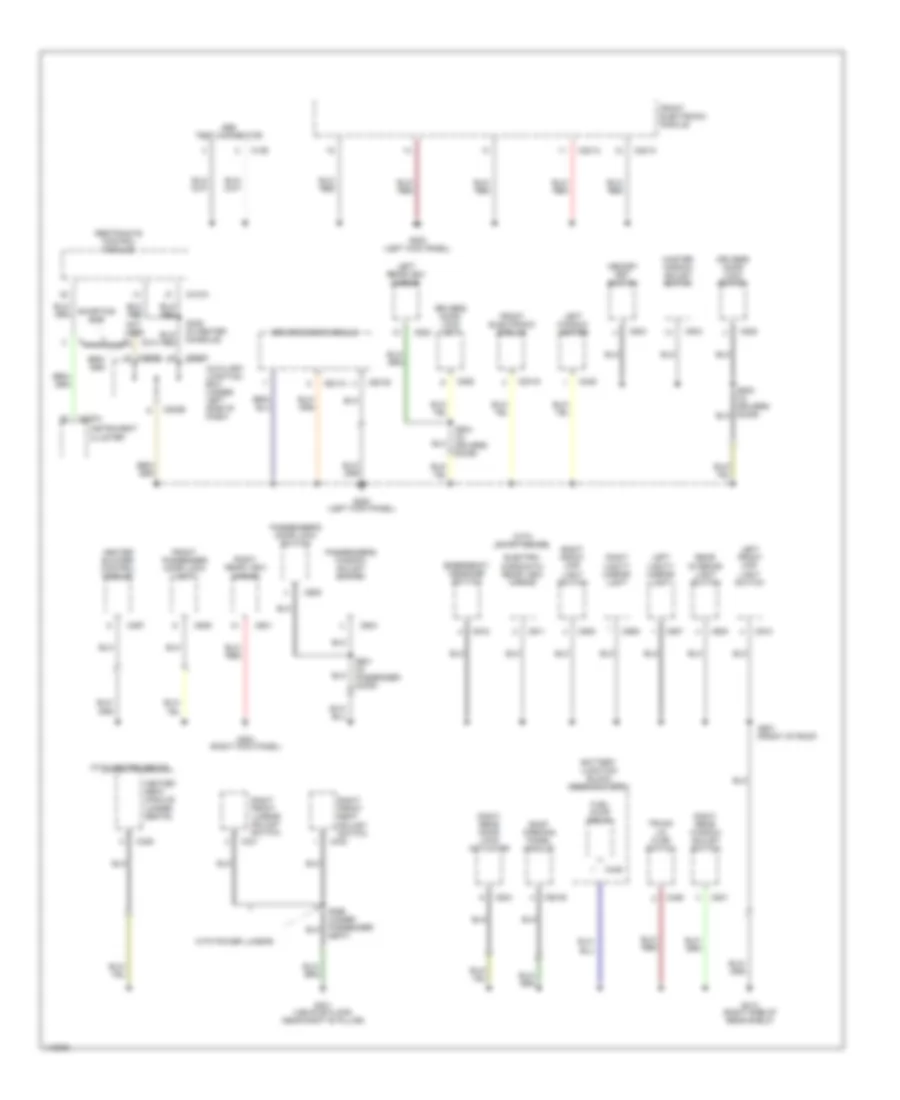
Ground Distribution Wiring Diagram (3 of 3) for Lincoln LS 2001
 https://portal-diagnostov.com/license.html
Automotive Electricians Portal FZCO
Automotive Electricians Portal FZCO
https://portal-diagnostov.com/license.html
https://portal-diagnostov.com/license.html
Automotive Electricians Portal FZCO
Automotive Electricians Portal FZCOList of elements for Ground Distribution Wiring Diagram (3 of 3) for Lincoln LS 2001:
- Antenna
- Ashtray illumination lamp
- Battery
- C307
- C308
- C319
- C324
- C341b
- C341c
- C342
- C344
- C359
- C360
- C361
- C381
- C401a
- C403a
- C404
- C420b
- C420c
- C420d
- C420f
- C420g
- C424
- C425
- C430
- C439
- C466
- C701
- C704
- Cellular phone module (voice activated)
- Cellular phone module (w/o voice activated)
- Console power point
- Driver lumbar adjust switch
- Driver seat adjust switch (w/memory)
- Driver seat adjust switch (w/o memory)
- Driver seat module (w/memory)
- Except sport
- Front cigar lighter
- G300 (vehicle floor, near left 'c' pillar)
- G314 (left side of rear shelf)
- G401 (right front side of trunk)
- G404 (left rear side of trunk)
- G405 (right rear side of trunk)
- Left front heated seat module
- Left front seat heater switch
- Left rear door lock actuator
- Left rear window adjust switch
- Nca
- Rear electronic module
- Remote emergency satellite cellular unit (rescu)
- Right front seat heater switch
- S310 (in center console)
- S313 (under driver seat)
- S397 (under driver seat)
- S420 (in trunk)
- Safety belt buckle switch
- Shield
- Subwoofer amplifier
- Tcs disable switch illumination lamp
- Trailer exterior lamp relay
- Trailer tow connector
- Trailer tow control unit
- Transmission shift selector
- Trunk lid release solenoid
- W/automatic transmission
- W/heated seats
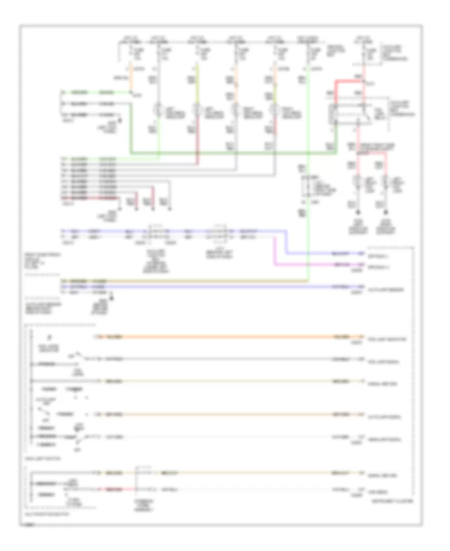
HEADLIGHTS
Headlights Wiring Diagram for Lincoln LS 2001
 https://portal-diagnostov.com/license.html
Automotive Electricians Portal FZCO
Automotive Electricians Portal FZCO
https://portal-diagnostov.com/license.html
https://portal-diagnostov.com/license.html
Automotive Electricians Portal FZCO
Automotive Electricians Portal FZCOList of elements for Headlights Wiring Diagram for Lincoln LS 2001:
- 10a
- 10k ohms
- 15-le42
- 1780 ohms
- 1k ohms
- 2200 ohms
- 29-dk20
- 31-dk20
- 31-dk20a
- 31-dk20b
- 31-dk20c
- 31-dk20d
- 31-le42
- 31s-ld9
- 31s-le15
- 31s-le16
- 31s-le22
- 31s-le23
- 330 ohms
- 4-eg11
- 4180 ohms
- 470 ohms
- 5-eg11
- 780 ohms
- 8-le42
- Autolamp on
- Autolamp sensor
- Autolamp sensor (behind right side of dash)
- Autolamp signal
- Auxiliary junction box (interior) (under left side of dash)
- Auxiliary junction box (underhood)
- C201a
- C201c
- C220a
- C220b
- C220c
- C261
- C270a
- C270b
- C270c
- C283c
- C283d
- Central junction box
- Flash to pass
- Fog lamp indicator
- Fog lamp relay
- Fog lamp signal
- Fog lamps
- Fog lamps indicator
- Front electronic module (in left "a" pillar)
- Fuse
- Fuse 15a
- G108 (left radiator support)
- G109 (right radiator support)
- G200 (left kick panel)
- G206 (behind center of dash)
- Headlamp signal
- High beam
- Hot at all times
- Hot in run or start
- Instrument cluster
- J/c 1 (behind right side of dash)
- J/c 4 (behnind left side of dash)
- Left front fog lamp
- Left high beam headlamp
- Left low beam headlamp
- Low beam
- Main light switch
- Multifunction switch
- Off
- Park
- Red
- Red/ (front right side of engine compt) s134
- Right high beam headlamp
- Right low beam headlamp
- S137
- S153
- Scp bus (-)
- Signal return
- Sps bus (+)
- Steering wheel assembly
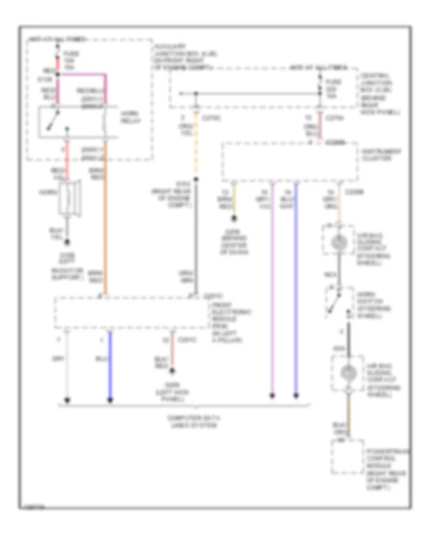
HORN
Horn Wiring Diagram for Lincoln LS 2001
 https://portal-diagnostov.com/license.html
Automotive Electricians Portal FZCO
Automotive Electricians Portal FZCO
https://portal-diagnostov.com/license.html
https://portal-diagnostov.com/license.html
Automotive Electricians Portal FZCO
Automotive Electricians Portal FZCOList of elements for Horn Wiring Diagram for Lincoln LS 2001:
- (2000)
- (2001)
- (2001) (2000)
- (behind center of dash)
- (behind right kick panel)
- (right rear of engine compt)
- (steering wheel)
- Air bag sliding contact
- Auxiliary junction box (ajb) (in front right of engine compt)
- C201c
- C220b
- C270a
- C270c
- Central junction box (cjb)
- Computer data lines system
- Front electronic module (fem) (in left a-pillar)
- Fuse 10a
- Fuse 15a
- G108 (left
- G200 (left kick panel)
- G206
- Horn
- Horn relay
- Horn switch (steering wheel)
- Hot at all times
- Instrument cluster
- Nca
- Powertrain control module
- Radiator support)
- Red
- S139
- S153
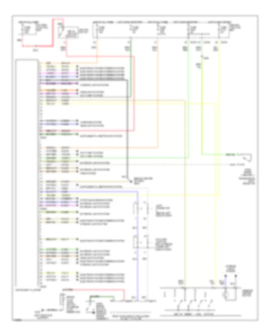
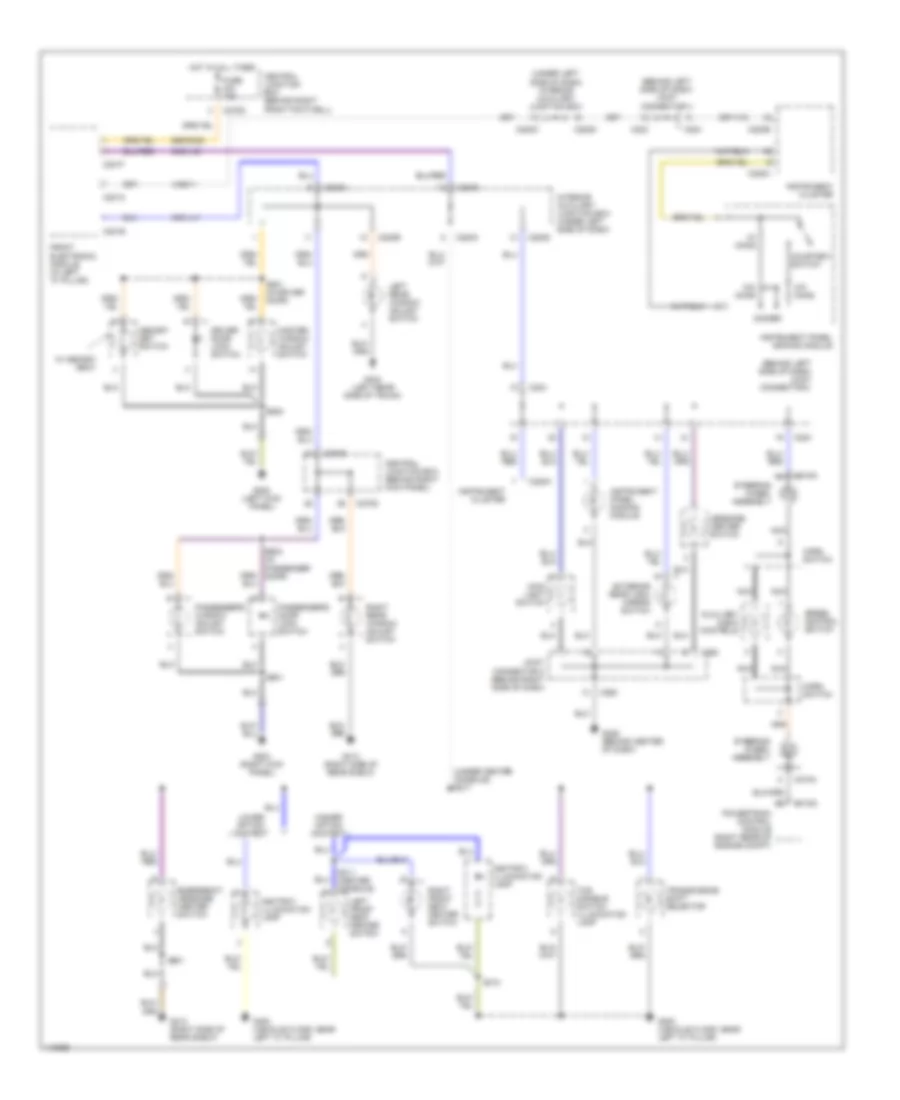
INSTRUMENT CLUSTER
Instrument Cluster Wiring Diagram for Lincoln LS 2001
 https://portal-diagnostov.com/license.html
Automotive Electricians Portal FZCO
Automotive Electricians Portal FZCO
https://portal-diagnostov.com/license.html
https://portal-diagnostov.com/license.html
Automotive Electricians Portal FZCO
Automotive Electricians Portal FZCOList of elements for Instrument Cluster Wiring Diagram for Lincoln LS 2001:
- (behind center of dash)
- (left radiator support)
- 10-gj9
- 10-gl36
- 10-gl6
- 10-le47
- 15-gg14
- 15-ja14
- 29-al12
- 29-gg11
- 30s-gm7
- 31-al11
- 31s-bb12
- 31s-ja14
- 32-al6
- 33-al6
- 34-al7
- 35-al7
- 4-eg8
- 5-eg8
- 64s-lk29
- 7-al17
- 7-gg25
- 7-ld13
- 7-ld7
- 75-gg15
- 8-al10
- 8-al16
- 8-al17
- 8-ge52
- 8-gl36
- 8-ja13
- 8-ld10
- 8-le10
- 8-le14
- 8-le21
- 8-le42
- 8-lg43
- 8-ta34
- 9-al10
- 9-al17
- 9-gg25
- 9-le10
- 9-le29
- 9-lg43
- 91-gg11
- Anti-theft system
- Auxiliary junction box (interior) (under left side of dash)
- Battery junction box
- Brake fluid level switch (on brake fluid reservoir)
- C201c
- C201f
- C220a
- C220b
- C220c
- C270a
- C270d
- Central junction box
- Electronic power steering system
- Electronic power steering system electronic power steering system
- Exterior lights system
- Front electronic module (fem) (in left "a" pillar)
- Fuel
- Fuse f204 5a
- Fuse f213 5a
- Fuse f217 5a
- Fuse f219 15a
- Fuse f220 10a
- Fuse f422 20a
- G108
- G206
- Headlights system
- Horn system
- Hot at all times
- Hot in accy or run
- Hot in run or start
- Ignition switch
- Instrument cluster
- Interior lights system
- Interior lights sytem
- Joint connector (behind left side of dash)
- Key-in ignition switch
- Message center switch
- Park brake switch (base of parking brake assembly)
- Park sense switch
- Red
- Reset
- S205
- S213
- Set up
- Starting/charging system
- Status
- Transmission shift selector
- Warnings system
INTERIOR LIGHTS
Courtesy Lamps Wiring Diagram for Lincoln LS 2001
 https://portal-diagnostov.com/license.html
Automotive Electricians Portal FZCO
Automotive Electricians Portal FZCO
https://portal-diagnostov.com/license.html
https://portal-diagnostov.com/license.html
Automotive Electricians Portal FZCO
Automotive Electricians Portal FZCOList of elements for Courtesy Lamps Wiring Diagram for Lincoln LS 2001:
- (front of roof) s902
- 29-dk20
- 29-dk31
- 29s-lc3
- 31-dk20a
- 31-dk30h
- 31s-gl12
- 31s-gl19
- 31s-gl46
- 31s-gl47
- 31s-lb25
- 4-eg11
- 4-eg12
- 8-gl20
- Battery junction box (in luggage compt, near battery)
- C201a
- C201c
- C201e
- C201f
- C224
- C261
- C270a
- C270c
- C270d
- C283a
- C283b
- C283c
- C283d
- C420a
- C420b
- C420c
- C420d
- Central junction box (behind right kick panel)
- Door ajar
- Driver's door lock unit
- Front electronic module (in left "a" pillar)
- Fuse 10a
- G200 (left kick panel)
- G203 (right kick panel)
- G206 (behind center of dash)
- G313 (right side of rear shelf)
- G404 (left rear side of trunk)
- G405 (right rear side of trunk)
- Glove box lamp
- Hot at all times
- Interior auxiliary junction box (under left side of dash)
- Joint connector 1 (behind right side of dash)
- Joint connector 3 (behind left side of dash)
- Left front door entry lamp
- Left front footwell lamp
- Left front map reading lamp
- Left front map reading lamp switch
- Left rear door lock actuator
- Left vanity mirror lamp
- Luggage compartment lamp
- Luggage compt lid ajar switch
- Passenger's door lock switch
- Rear electronic module (right side of luggage compt)
- Rear interior lamp
- Rear interior lamp switch
- Right front door entry lamp
- Right front footwell lamp
- Right front map reading lamp
- Right front map reading lamp switch
- Right rear door lock actuator
- Right vanity mirror lamp
- S153
- S312
- S430
- S504
- S601
- S900 (front of roof)
- S901
Instrument Illumination Wiring Diagram for Lincoln LS 2001
 https://portal-diagnostov.com/license.html
Automotive Electricians Portal FZCO
Automotive Electricians Portal FZCO
https://portal-diagnostov.com/license.html
https://portal-diagnostov.com/license.html
Automotive Electricians Portal FZCO
Automotive Electricians Portal FZCOList of elements for Instrument Illumination Wiring Diagram for Lincoln LS 2001:
- (behind left side of dash) joint connector 3
- (behind left side of dash) joint connector 4
- (under center console) s217
- (under left side of dash) interior auxiliary junction box
- 10k ohms
- 1k ohms
- 29s-dk22
- 4-eg11
- 64s-lh1
- 64s-lh2
- Ashtray illumination lamp
- Auxiliary audio controls
- C175a
- C201c
- C201e
- C201f
- C218a
- C220a
- C220b
- C220c
- C223
- C224
- C262
- C270d
- C283a
- C283b
- C283c
- C283d
- Central junction box (behind right front footwell)
- Central junction box (behind right kick panel)
- Courtesy switch
- Dimmer
- Driver door lock switch
- Emergency message center switch
- Exterior rear view mirror switch
- Front electronic module (in left "a" pillar)
- Fuse 10a
- G200 (left kick panel)
- G203 (right kick panel)
- G206 (behind center of dash)
- G300 (vehicle floor, near left "c" pillar)
- G313 (right side of rear shelf)
- G404 (left rear side of trunk)
- Higher option content
- Horn switch
- Hot at all times
- Instrument cluster
- Instrument panel dimming module
- Instrument panel dimming module
- Interior auxiliary junction box (under left side of dash)
- Joint connector 2 (behind right side of dash)
- Left front seat heater switch
- Left rear window adjust switch
- Lower option content
- Main light switch
- Master window adjust switch
- Memory set switch
- Message center switch
- Nca
- Ohms
- Passenger's door lock switch
- Passenger's window adjust switch
- Powertrain control module (right rear of engine compt)
- Right front seat heater switch
- Right rear window adjust switch
- S310
- S311 (center console)
- S501 (in driver door)
- S502
- S601
- S602 (in passenger door)
- S901
- Speed control switch
- Steering wheel assembly
- Tcs disable switch illumination lamp
- Transmission shift selector
- W/ memory seat
MEMORY SYSTEMS
Memory Mirrors Wiring Diagram for Lincoln LS 2001
 https://portal-diagnostov.com/license.html
Automotive Electricians Portal FZCO
Automotive Electricians Portal FZCO
https://portal-diagnostov.com/license.html
https://portal-diagnostov.com/license.html
Automotive Electricians Portal FZCO
Automotive Electricians Portal FZCOList of elements for Memory Mirrors Wiring Diagram for Lincoln LS 2001:
- (2000)
- (2001)
- (left kick panel) g200
- 10-ad18
- 10-ad19
- 29-aj80
- 29s-aj86
- 29s-dk21
- 31-aj80b
- 31-dk20a
- 32-ad10
- 32-ad30
- 32-ad32
- 32-ad7
- 33-ad10
- 33-ad12
- 33-ad7
- 34-ad11
- 34-ad29
- 34-ad31
- 34-ad8
- 35-ad11
- 35-ad8
- 4-eg11
- 4-eg13
- 5-eg11
- 5-eg13
- 7-ad18
- 7-ad19
- 7s-ah27
- 8-ad18
- 8-ad19
- 8-ah27
- 8-ah31
- 8-ah32
- 9-ad18
- 9-ad19
- 91-aj80
- Auxiliary junction box (interior) (under left side of dash)
- C201a
- C201c
- C201e
- C270c
- C270d
- C270e
- C283a
- C283c
- C501a
- C501c
- C501d
- C520
- C601
- Central junction box (behind right kick panel)
- Defogger system
- Direct- tional switch
- Driver door module (ddm) (in driver's door)
- Driver side exterior rear view mirror
- Exterior rear view mirror switch
- Front electronic module (fem) (in left "a" pillar)
- Fuse 10a
- Fuse 5a
- G200 (left kick panel)
- Heated mirror
- Hot at all times
- L/r sens
- Left/ right
- Left/right mirror select switch
- Memory set switch
- Nca
- Passanger side exterior rear view mirror
- S210
- S502
- S504
- Set
- U/d sens
- Up/ down
Memory Seat Wiring Diagram for Lincoln LS 2001
 https://portal-diagnostov.com/license.html
Automotive Electricians Portal FZCO
Automotive Electricians Portal FZCO
https://portal-diagnostov.com/license.html
https://portal-diagnostov.com/license.html
Automotive Electricians Portal FZCO
Automotive Electricians Portal FZCOList of elements for Memory Seat Wiring Diagram for Lincoln LS 2001:
- (left kick panel) g200
- (under driver seat) s394
- (under driver seat) s395
- (vehicle floor, near left "c" pillar) g300
- 10-ah82
- 10-ah83
- 10-ah84
- 10-ah85
- 29-ah80
- 30-ah80
- 31-ah80
- 32-ah36
- 32-ah37
- 32-ah38
- 32-ah41
- 33-ah36
- 33-ah37
- 33-ah38
- 33-ah41
- 4-ah80
- 4-eg13
- 5-ah80
- 5-eg13
- 7-ah30
- 7-ah80
- 7s-ah27
- 8-ah24
- 8-ah25
- 8-ah26
- 8-ah27
- 8-ah30
- 8-ah31
- 8-ah32
- 8-ah82
- 8-ah83
- 8-ah84
- 8-ah85
- 9-ah30
- 9-ah80
- 91-ah80
- Auxiliary junction box (interior) (under left side of dash)
- Battery junction box (in luggage compt, near battery)
- C270d
- C283a
- C341a
- C341b
- C341c
- C360
- C501a
- C501d
- Central junction box (behind right kick panel)
- Driver door module (ddm) (in driver's door)
- Driver memory backrest sensor
- Driver memory seat front height sensor
- Driver memory seat horizontal sensor
- Driver memory seat rear height sensor
- Driver seat module (under driver's seat)
- Front up/ down
- Fuse 20a
- Fuse 5a
- G300 (vehicle floor, near left "c" pillar)
- Hot at all times
- Left front seat adjust switch (on left front seat)
- Left front seat backrest motor
- Left front seat front height motor
- Left front seat horizontal motor
- Left front seat rear height motor
- Memory set switch
- Rear up/ down
- Recline up/ down
- Red
- S210
- S313
- S393
- S396
- S397
- S502
- Seat fwd/ back
- Set
Steering Column Memory Wiring Diagram for Lincoln LS 2001
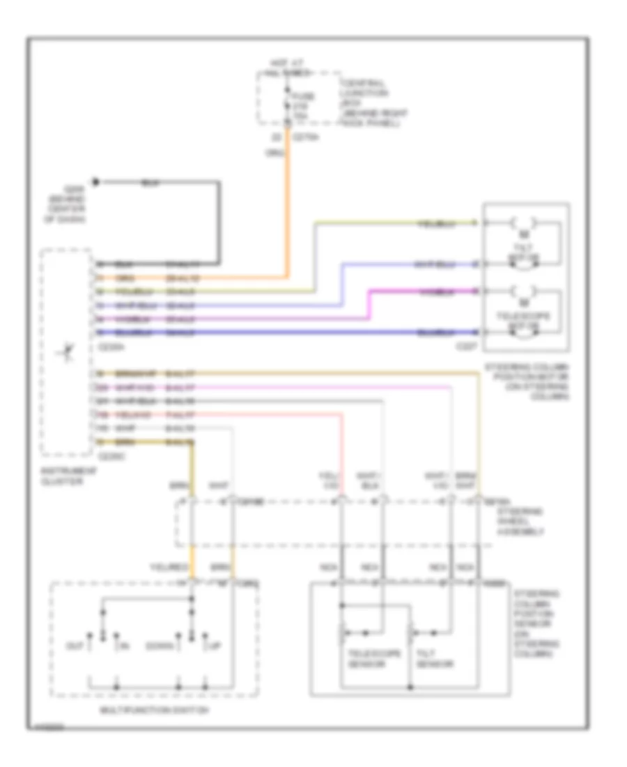 https://portal-diagnostov.com/license.html
Automotive Electricians Portal FZCO
Automotive Electricians Portal FZCO
https://portal-diagnostov.com/license.html
https://portal-diagnostov.com/license.html
Automotive Electricians Portal FZCO
Automotive Electricians Portal FZCOList of elements for Steering Column Memory Wiring Diagram for Lincoln LS 2001:
- 29-al12
- 31-al11
- 32-al6
- 33-al6
- 34-al6
- 35-al6
- 7-al17
- 8-al10
- 8-al16
- 8-al17
- 9-al10
- 9-al17
- C202
- C218a
- C218b
- C220a
- C220c
- C222
- C227
- C270a
- Central junction box (behind right kick panel)
- Down
- Fuse 15a
- G206 (behind center of dash)
- Hot at all times
- Instrument cluster
- Multifunction switch
- Nca
- Out
- Steering column position motor (on steering column)
- Steering column postion sensor (on steering column)
- Steering wheel assembly
- Telescope motor
- Telescope sensor
- Tilt motor
- Tilt sensor
NAVIGATION
Vehicle Emergency Messaging Wiring Diagram for Lincoln LS 2001
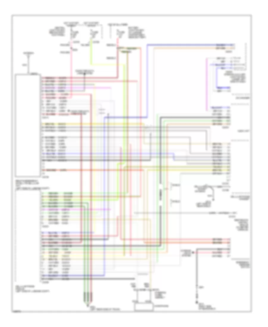 https://portal-diagnostov.com/license.html
Automotive Electricians Portal FZCO
Automotive Electricians Portal FZCO
https://portal-diagnostov.com/license.html
https://portal-diagnostov.com/license.html
Automotive Electricians Portal FZCO
Automotive Electricians Portal FZCOList of elements for Vehicle Emergency Messaging Wiring Diagram for Lincoln LS 2001:
- 1-gp11
- 1-mc10
- 1-mc9
- 10-gp6
- 10-gp9
- 10-mc10
- 2-gp10
- 2-mc10
- 2-mc9
- 20-gp8
- 30-gp8
- 30-mc9b
- 30-mc9c
- 31-gp8
- 31-mc10
- 31-mc10a
- 31-mc9f
- 31-md9d
- 4-gp14
- 4-gp8
- 4-mc10
- 4-mc9
- 48-mc10a
- 48-mc8
- 48-md10
- 48-md15b
- 5-gp12
- 5-gp8
- 5-mc10
- 5-mc9
- 7-mc10
- 75-mc9
- 8-gp13
- 8-gp6
- 8-gp8
- 8-mc10
- 8-mc8
- 8-md15
- 9-gp6
- 9-mc10
- 9-mc8
- 91-mc10
- Antenna
- Audio unit
- Battery junction box (in luggage compartment, near battery)
- C218a
- C218b
- C240a
- C270d
- C270e
- C283a
- C283d
- C310a
- C318a
- C318b
- C401a
- C401b
- C401c
- C403a
- C403b
- Cd changer
- Cellular phone antenna
- Cellular phone handset
- Cellular phone module (left side of luggage compt)
- Central junction box (behind right kick panel)
- Computer data lines system
- Emergency message switch
- Fuse 5a
- G313 (right side of rear shelf)
- G314 (left side of rear shelf)
- G404 (left rear side of trunk)
- Hot at all times
- Hot in start or run
- Interior auxiliary junction box (under left side of dash)
- Interior lights system
- Microphone
- Nca
- Remote emergency satellite cellular unit (left side of luggage compt)
- Restraints control module (in center console)
- S228
- S411
- S901
- Shield
- Steering wheel asembly
POWER DISTRIBUTION
Power Distribution Wiring Diagram (1 of 5) for Lincoln LS 2001
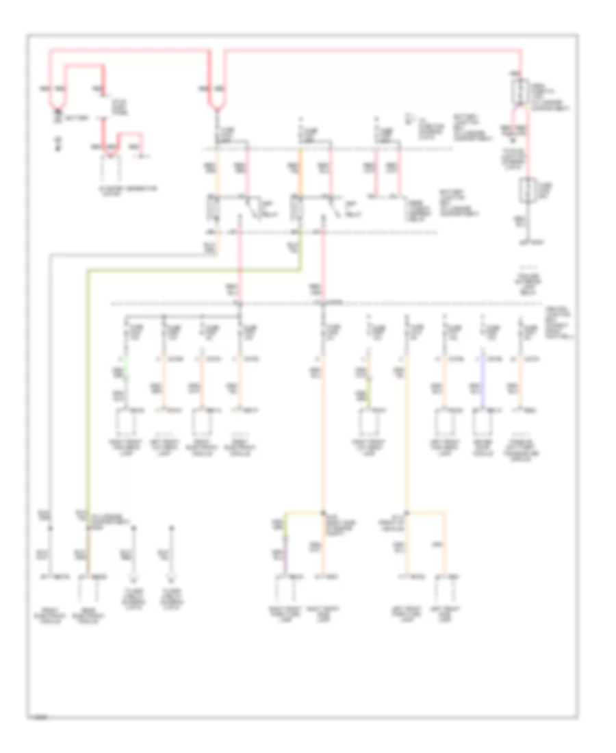 https://portal-diagnostov.com/license.html
Automotive Electricians Portal FZCO
Automotive Electricians Portal FZCO
https://portal-diagnostov.com/license.html
https://portal-diagnostov.com/license.html
Automotive Electricians Portal FZCO
Automotive Electricians Portal FZCOList of elements for Power Distribution Wiring Diagram (1 of 5) for Lincoln LS 2001:
- Battery
- Battery junction box (in luggage compartment)
- C1020
- C1021
- C1022
- C1040
- C1041
- C1042
- C151
- C161
- C201a
- C201b
- C201f
- C252
- C270a
- C270b
- C270c
- C270d
- C270e
- C420d
- C424
- C501a
- Central junction box (in right front footwell)
- Driver door module
- Front electronic module
- Fuse f208 5a
- Fuse f209 10a
- Fuse f210 5a
- Fuse f211 10a
- Fuse f222 10a
- Fuse f223 10a
- Fuse f224 5a
- Fuse f225 10a
- Fuse f230 5a
- Fuse f233 10a
- Fuse f427 30a
- Fuse f429 30a
- Fuse f432 30a
- Fuse f439 60a
- Generator
- Left front high beam lamp
- Left front low beam lamp
- Left front park/turn lamp
- Left front side lamp
- Mega fuse f18 175a (in luggage compartment)
- Passive anti-theft transceiver module
- Rear electronic module
- Rear window defrost relay
- Red
- Right front high beam lamp
- Right front low beam lamp
- Right front park/turn lamp
- Right front side lamp
- S108 (right side of engine compt)
- S114 (front of vehicle)
- Ssp relay
- Starter motor
- Stud dash panel
- To fuse f428 (diagram 2 of 5)
- To ssp 3 relay (diagram 2 of 5)
- To ssp 4 relay (diagram 2 of 5)
- To stud junction (diagram 4 of 5)
- Trailer exterior lamp relay
Power Distribution Wiring Diagram (2 of 5) for Lincoln LS 2001
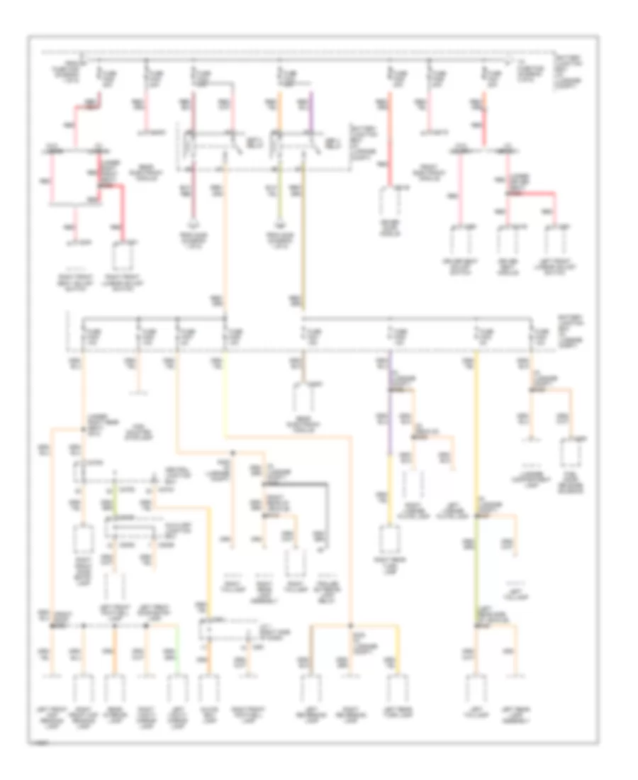 https://portal-diagnostov.com/license.html
Automotive Electricians Portal FZCO
Automotive Electricians Portal FZCO
https://portal-diagnostov.com/license.html
https://portal-diagnostov.com/license.html
Automotive Electricians Portal FZCO
Automotive Electricians Portal FZCOList of elements for Power Distribution Wiring Diagram (2 of 5) for Lincoln LS 2001:
- (in luggage compt) s422
- (in luggage compt) s427
- (in luggage compt) s430
- (left rear side of vehicle) s400
- (right rear of vehicle) s416
- (under red driver seat) s393
- (under right rear seat) s312
- (under right red front seat) s398
- (w/ lumbar)
- (w/ memory)
- (w/o lumbar)
- (w/o memory)
- Auxiliary junction box
- Battery junction box (in luggage compt)
- C201d
- C261
- C270a
- C270d
- C283b
- C283d
- C330
- C331
- C341b
- C360
- C361
- C409
- C420c
- C420g
- C501b
- Central junction box
- Driver door module
- Driver seat adjust switch
- Driver seat module
- From a
- From s429 (diagram 1 of 5)
- Front electronic module
- Fuel door release solenoid
- Fuse f401 15a
- Fuse f402 10a
- Fuse f403 5a
- Fuse f404 10a
- Fuse f405 10a
- Fuse f406 10a
- Fuse f407 5a
- Fuse f408 10a
- Fuse f420 20a
- Fuse f421 20a
- Fuse f423 30a
- Fuse f424 30a
- Fuse f426 20a
- Fuse f428 20a
- Fuse f429 (diagram 1 of 5)
- Fuse f430 20a
- Glove box lamp
- High mounted stoplamp
- J/c 1 (right side of dash)
- Left front door entry lamp
- Left front footwell lamp
- Left front lumbar adjust switch
- Left front map reading lamp
- Left license plate lamp
- Left rear lamp assembly
- Left rear turn lamp
- Left reversing lamp
- Left taillamp
- Left vanity mirror lamp
- Luggage compartment lamp
- Luggage compt) s433
- Rear electronic module
- Rear interior lamp
- Red
- Right front door entry lamp
- Right front footwell lamp
- Right front lumbar adjust switch
- Right front map reading lamp
- Right front seat adjust switch
- Right license plate lamp
- Right rear lamp assembly
- Right rear turn lamp
- Right reversing lamp
- Right taillamp
- Right vanity mirror lamp
- S423 (in luggage compt)
- S428 (in luggage compt)
- Ssp 3 relay
- Ssp 4 relay
- To fuse f425 (diagram 3 of 5)
- Trailer exterior lamp relay
Power Distribution Wiring Diagram (3 of 5) for Lincoln LS 2001
 https://portal-diagnostov.com/license.html
Automotive Electricians Portal FZCO
Automotive Electricians Portal FZCO
https://portal-diagnostov.com/license.html
https://portal-diagnostov.com/license.html
Automotive Electricians Portal FZCO
Automotive Electricians Portal FZCOList of elements for Power Distribution Wiring Diagram (3 of 5) for Lincoln LS 2001:
- (in driver side footwell) s210
- (left side luggage compt) s411
- (right front vehicle floor) s301
- (under driver seat) s396
- (w/ non-voice activated cell phone)
- (w/ voice activated cell phone)
- A/t
- Audio unit
- Autolamp sensor
- Battery junction box (in luggage compartment)
- Battery junction box (in luggage compt)
- Brake pedal position switch
- Brake pressure switch
- C102a
- C175a
- C201c
- C204
- C220a
- C220b
- C225
- C228a
- C240c
- C243
- C270a
- C270c
- C270d
- C277
- C278
- C287
- C329
- C341c
- C359
- C360
- C380
- C401a
- C403a
- C404
- C420d
- C420f
- C466
- C501a
- C921b
- Cd changer
- Cellular phone module
- Central junction box (right front footwell)
- Cigar lighter
- Data link connector
- Driver door module
- Driver seat adjust switch
- Driver seat module
- Electronic automatic temperature control module
- Exterior rear view mirror switch
- From f fuse f421 (diagram 2 of 5)
- Front electronic module
- Front remote amplifier (jbl system only)
- Fuel pump relay
- Fuse f206 10a
- Fuse f207 5a
- Fuse f218 20a
- Fuse f219 15a
- Fuse f220 10a
- Fuse f232 20a
- Fuse f235 5a
- Fuse f410 20a
- Fuse f411 15a
- Fuse f414 5a
- Fuse f415 5a
- Fuse f416 20a
- Fuse f417 15a
- Fuse f418 20a
- Fuse f419 20a
- Fuse f422 20a
- Fuse f425 40a
- Fuse f431 20a
- G308 (vehicle floor near left "b" pillar)
- Generator
- Instrument cluster
- Left front heated seat module
- M/t
- Memory)
- Of dash) s211
- Phone)
- Power point (console)
- Powertrain control module
- Rear electronic module
- Red
- Remote emergency satellite cellular unit
- Right front heated seat module
- Roof opening panel module
- Subwoofer amplifier
- To ignition switch (diagram 5 of 5)
Power Distribution Wiring Diagram (4 of 5) for Lincoln LS 2001
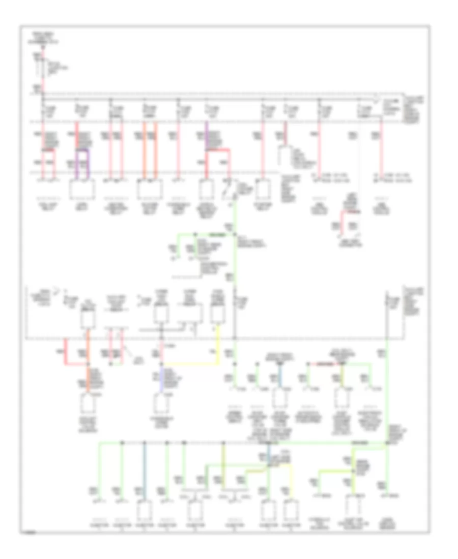 https://portal-diagnostov.com/license.html
Automotive Electricians Portal FZCO
Automotive Electricians Portal FZCO
https://portal-diagnostov.com/license.html
https://portal-diagnostov.com/license.html
Automotive Electricians Portal FZCO
Automotive Electricians Portal FZCOList of elements for Power Distribution Wiring Diagram (4 of 5) for Lincoln LS 2001:
- (3.0l only) (rear engine compt) s156
- (3.0l)
- (3.9l only)
- (3.9l)
- (left rear engine compt) s122
- (rear engine compt) s125
- (right front engine compt) s105
- (right front of engine compt) s104
- (right red
- (top of (right side of engine) (3.9l only) s150
- (w/ ivd)
- (w/o ivd)
- A/c clutch relay
- Abs control module
- Abs test connector
- Air pump relay (california 3.0l only)
- Automatic transmission (if equipped)
- Auxiliary coolant pump relay
- Auxiliary junction box (right side engine compt)
- Auxiliary junction box (right side of engine compt)
- Blower motor relay
- C1034
- C105
- C119
- C122
- C123
- C125
- C128
- C135
- C136a
- C155
- C168
- C175a
- C179
- C191
- C450
- Coolant control valve solenoid
- Cops & heated o2 sensor relay
- Electronic vacuum regulator solenoid valve
- Engine) (3.0l only) s128
- Evap canister purge valve
- Evap canister vent valve
- Fog lamp relay
- From h fuse f114 (diagram 4 of 5)
- From mega fuse f18 (diagram 1 of 5)
- Front engine compt) s137
- Front engine compt) s139
- Front of engine compt)
- Fuse f101 10a
- Fuse f103 15a
- Fuse f104 15a
- Fuse f105 20a
- Fuse f106 15a
- Fuse f113 30a
- Fuse f114 30a
- Fuse f116 30a
- Fuse f117 20a
- Fuse f118 40a
- Fuse f120 30a
- Fuse f121 30a
- Fuse f122 30a
- Fuse f123
- Heated wiper/park relay
- Horn relay
- Hydraulic fan solenoid
- Injector
- Inlet air control valve solenoid
- Inlet manifold runner control module (3.0l only)
- Mass airflow sensor
- Pcm power relay
- Powertrain control module
- Red
- S111 (right front engine compt)
- S136 (right front engine compt)
- Speed control servo
- Starter relay
- Stud junction box
- To fuse f101 (diagram 4 of 5)
- Wind- shield wiper relay
- Windshield wiper motor
- Windshield wiper relay
- Wiper high/ low relay
- Wiper run/ park relay
Power Distribution Wiring Diagram (5 of 5) for Lincoln LS 2001
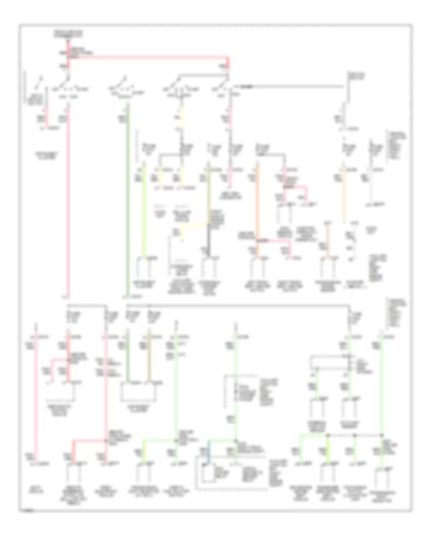 https://portal-diagnostov.com/license.html
Automotive Electricians Portal FZCO
Automotive Electricians Portal FZCO
https://portal-diagnostov.com/license.html
https://portal-diagnostov.com/license.html
Automotive Electricians Portal FZCO
Automotive Electricians Portal FZCOList of elements for Power Distribution Wiring Diagram (5 of 5) for Lincoln LS 2001:
- (a/t)
- (behind dash panel) (w/ rescu) s228
- (behind dash panel) red
- (center console)
- (center console) s306
- (driver side footwell) s205
- (m/t)
- (right side of engine compt) s140
- Abs test connector
- Acc
- Audio unit
- Autolamp sensor
- Auxiliary junction box (right side engine compt)
- C137
- C167
- C201f
- C220a
- C220b
- C226
- C228a
- C240c
- C270a
- C270b
- C270c
- C270d
- C270e
- C282
- C287
- C307
- C308
- C310a
- C329
- C342
- C344
- C359
- C401a
- C403a
- C911
- C914
- Cellular phone module
- Central junction box (right front foot- well)
- Cops & heated o2 sensor relay
- Driver side heated seat module
- Eatc module
- Electro- chromatic inside mirror unit
- From fuse f422 (diagram 3 of 5)
- Front electronic module
- Fuse 10a
- Fuse f201 5a
- Fuse f202 5a
- Fuse f203 5a
- Fuse f204 5a
- Fuse f205 5a
- Fuse f213 5a
- Fuse f214 10a
- Fuse f216 5a
- Fuse f217 5a
- Fuse f227 10a
- Fuse f229 5a
- Ignition switch
- Inertia fuel shutoff switch
- Instrument cluster
- J/c 1 (right side of dash)
- Key-in ignition switch
- Left front seat heater switch
- Off
- Passenger side heated seat module
- Pcm module power diode
- Pcm power relay
- Pnk
- Pnk/ (w/ rescu)
- Pnk/ (w/o rescu)
- Rain sensor module
- Red
- Remote emergency satellite cellular unit (rescu)
- Restraints control module
- Right front seat heater switch
- Run
- S213
- S309
- Start
- Starter relay
- Steering position sensor
- Tcs disable switch illumination lamp
- Transmission range sensor
- Transmission shift selector
- Transmission shift selector (a/t only)
- Windshield washer pump motor
- Windshield wiper relay
POWER DOOR LOCKS
Power Door Locks Wiring Diagram for Lincoln LS 2001
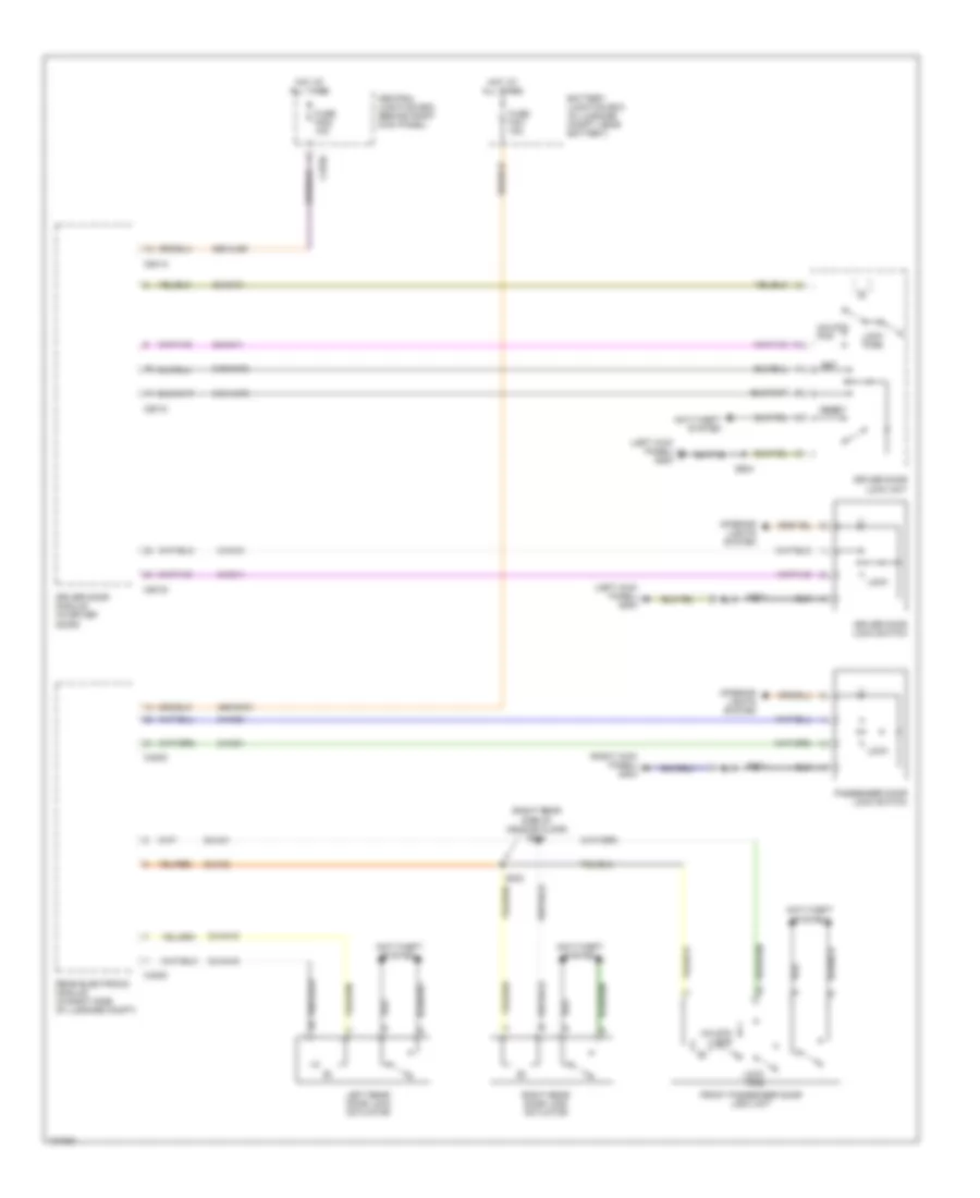 https://portal-diagnostov.com/license.html
Automotive Electricians Portal FZCO
Automotive Electricians Portal FZCO
https://portal-diagnostov.com/license.html
https://portal-diagnostov.com/license.html
Automotive Electricians Portal FZCO
Automotive Electricians Portal FZCOList of elements for Power Door Locks Wiring Diagram for Lincoln LS 2001:
- (left kick panel) g200
- (right kick panel) g203
- (right rear side of vehicle floor) s304
- 29s-aj86
- 29s-dk31
- 31s-aa78
- 31s-aa79
- 32-aa1
- 32-aa11
- 32-aa2
- 33-aa10
- 33-aa15
- 33-aa16
- 8-aa10
- 8-aa11
- 8-aa20
- 8-aa21
- Anti-theft system
- Battery junction box (in luggage compt, near battery)
- C270e
- C420c
- C501a
- C501c
- C501d
- Central junction box (behind right kick panel)
- Driver door lock switch
- Driver door lock unit
- Driver door module (in driver door)
- Front passenger door lock unit
- Fuse f222 10a
- Fuse f401 15a
- Hot at all times
- Interior lights system
- Left rear door lock actuator
- Lock
- Lock pos
- Passenger door lock switch
- Rear electronic module (in right side of luggage compt)
- Reset
- Right rear door lock actuator
- S303
- S502
- S504
- S601
- Set
- Unlock pos
POWER MIRRORS
Electrochromic Mirror Wiring Diagram for Lincoln LS 2001
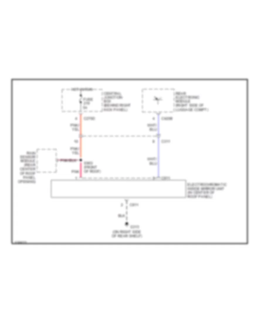 https://portal-diagnostov.com/license.html
Automotive Electricians Portal FZCO
Automotive Electricians Portal FZCO
https://portal-diagnostov.com/license.html
https://portal-diagnostov.com/license.html
Automotive Electricians Portal FZCO
Automotive Electricians Portal FZCOList of elements for Electrochromic Mirror Wiring Diagram for Lincoln LS 2001:
- (on right side of rear shelf)
- C270d
- C311
- C420b
- C911
- Central junction box (behind right kick panel)
- Electrochromatic inside mirror unit (in center of roof panel)
- Fuse 5a
- G313
- Hot in run
- Pnk
- Rain sensor module (rear center of roof panel opening)
- Rear electronic module (right side of luggage compt)
- S903 (front of roof)
Power Mirror Wiring Diagram for Lincoln LS 2001
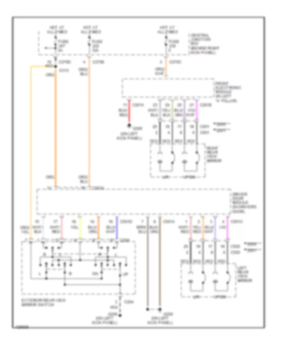 https://portal-diagnostov.com/license.html
Automotive Electricians Portal FZCO
Automotive Electricians Portal FZCO
https://portal-diagnostov.com/license.html
https://portal-diagnostov.com/license.html
Automotive Electricians Portal FZCO
Automotive Electricians Portal FZCOList of elements for Power Mirror Wiring Diagram for Lincoln LS 2001:
- (on left kick panel)
- C201a
- C201e
- C204
- C270c
- C270d
- C270e
- C501a
- C501c
- C501d
- C520
- C601
- Central junction box (behind right kick panel)
- Driver door module (in driver's door)
- Exterior rear view mirror switch
- Front electronic module (in left "a" pillar)
- Fuse
- Fuse 10a
- Fuse 5a
- G200
- G206
- Hot at all times
- L/r
- Left rear view mirror
- Nca
- Right rear view mirror
- S313
- Up/dn
POWER SEATS
Heated Seats Wiring Diagram for Lincoln LS 2001
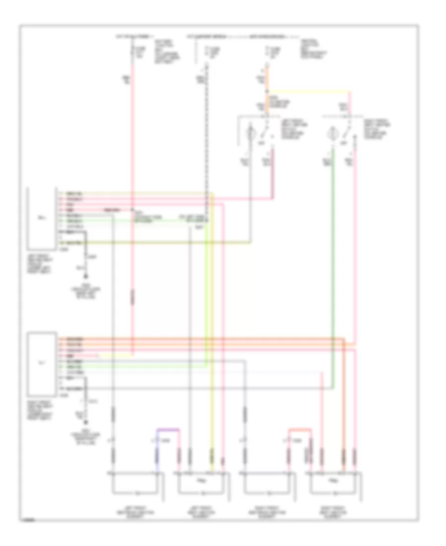 https://portal-diagnostov.com/license.html
Automotive Electricians Portal FZCO
Automotive Electricians Portal FZCO
https://portal-diagnostov.com/license.html
https://portal-diagnostov.com/license.html
Automotive Electricians Portal FZCO
Automotive Electricians Portal FZCOList of elements for Heated Seats Wiring Diagram for Lincoln LS 2001:
- (on left side of floor)
- Battery junction box (in luggage compt, near battery)
- C313
- C328
- C329
- C339
- C359
- Central junction box (behind right kick panel)
- Fuse f205 5a
- Fuse f216 5a
- Fuse f411 15a
- G300 (vehicle floor, near left "b" pillar)
- G301 (vehicle floor, near right "b" pillar)
- Hot at all times
- Hot in run or acc
- Hot in start or run
- Left front heated seat module (under left front seat)
- Left front seat heater switch (on center console)
- Left front seat heating element
- Left front seatback heating element
- Off
- Pnk
- Red
- Right front heated seat module (under right front seat)
- Right front seat heater switch (on center console)
- Right front seat heating element
- Right front seatback heating element
- S207
- S301 (on right side of floor)
- S309 (in center console)
- S397
Power Lumbar Seat Wiring Diagram for Lincoln LS 2001
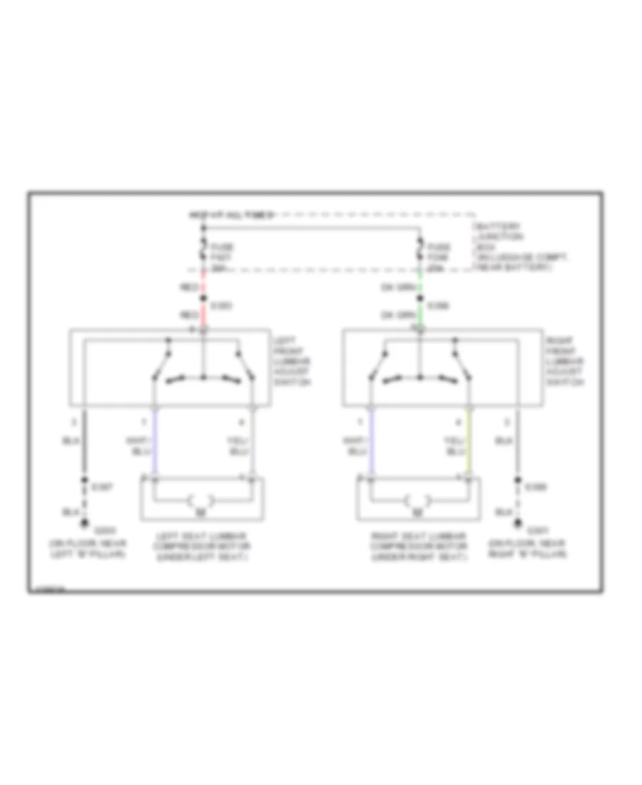 https://portal-diagnostov.com/license.html
Automotive Electricians Portal FZCO
Automotive Electricians Portal FZCO
https://portal-diagnostov.com/license.html
https://portal-diagnostov.com/license.html
Automotive Electricians Portal FZCO
Automotive Electricians Portal FZCOList of elements for Power Lumbar Seat Wiring Diagram for Lincoln LS 2001:
- (on floor, near left "b" pillar)
- (on floor, near right "b" pillar)
- Battery junction box (in luggage compt, near battery)
- Fuse f248 20a
- Fuse f421 20a
- G300
- G301
- Hot at all times
- Left front lumbar adjust switch
- Left seat lumbar compressor motor (under left seat)
- Red
- Right front lumbar adjust switch
- Right seat lumbar compressor motor (under right seat)
- S393
- S397
- S398
- S399
Power Seats Wiring Diagram for Lincoln LS 2001
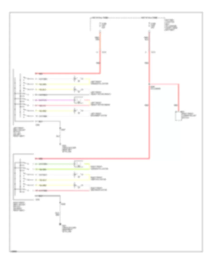 https://portal-diagnostov.com/license.html
Automotive Electricians Portal FZCO
Automotive Electricians Portal FZCO
https://portal-diagnostov.com/license.html
https://portal-diagnostov.com/license.html
Automotive Electricians Portal FZCO
Automotive Electricians Portal FZCOList of elements for Power Seats Wiring Diagram for Lincoln LS 2001:
- Battery junction box (in luggage compt, near battery)
- C313
- C315
- C330
- C331
- C360
- Fuse f421 20a
- Fuse f428 20a
- G300 (vehicle floor, near left "b" pillar)
- G301 (vehicle floor, near right "b" pillar)
- Hot at all times
- Left front backrest motor
- Left front height motor (front)
- Left front height motor (rear)
- Left front horizontal motor
- Left front seat adjust switch (on left front seat)
- Red
- Right front horizontal motor
- Right front lumbar adjust switch
- Right front seat adjust switch (on right front seat)
- Right front seatback motor
- Right front vertical motor
- S397
- S398 (w/lumbar)
- S399
POWER TOP/SUNROOF
Power Top/Sunroof Wiring Diagram for Lincoln LS 2001
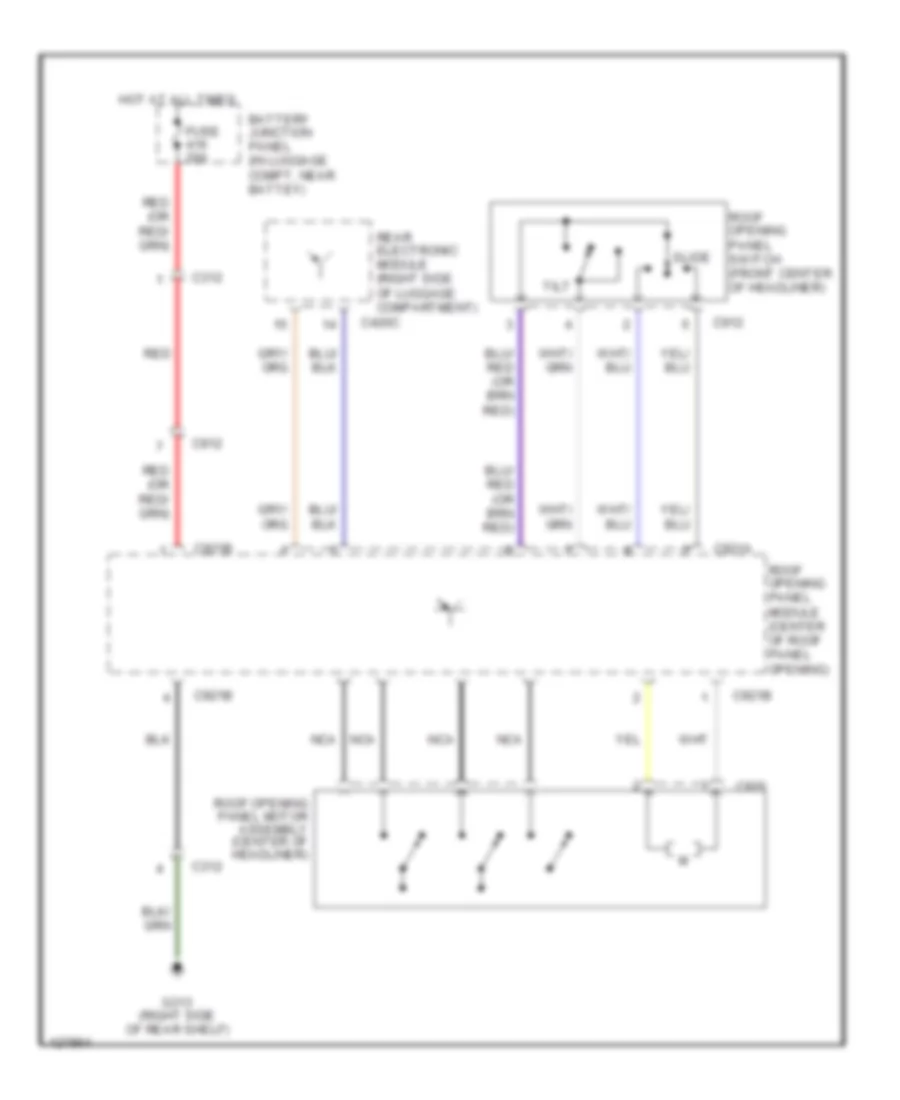 https://portal-diagnostov.com/license.html
Automotive Electricians Portal FZCO
Automotive Electricians Portal FZCO
https://portal-diagnostov.com/license.html
https://portal-diagnostov.com/license.html
Automotive Electricians Portal FZCO
Automotive Electricians Portal FZCOList of elements for Power Top/Sunroof Wiring Diagram for Lincoln LS 2001:
- Battery junction panel (in luggage compt, near battey)
- C312
- C420c
- C912
- C920
- C921a
- C921b
- Fuse 20a
- G313 (right side of rear shelf)
- Hot at all times
- Nca
- Rear electronic module (right side of luggage compartment)
- Red
- Roof opening panel module (center of roof panel opening)
- Roof opening panel motor assembly (center of headliner)
- Roof opening panel switch (front center of headliner)
- Slide
- Tilt
POWER WINDOWS
Power Windows Wiring Diagram for Lincoln LS 2001
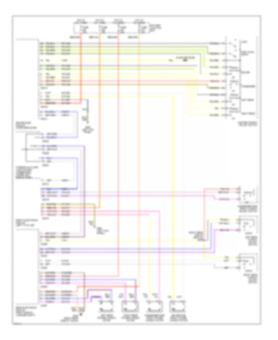 https://portal-diagnostov.com/license.html
Automotive Electricians Portal FZCO
Automotive Electricians Portal FZCO
https://portal-diagnostov.com/license.html
https://portal-diagnostov.com/license.html
Automotive Electricians Portal FZCO
Automotive Electricians Portal FZCOList of elements for Power Windows Wiring Diagram for Lincoln LS 2001:
- (in driver door) s503
- (right rear end of vehicle) s409
- 10-aj14
- 10-aj18
- 10-aj24
- 30-aj71
- 30-aj80
- 30-dk30
- 30-dk30a
- 31-aj71
- 31-aj80
- 31-dk30a
- 31-dk30b
- 32-aj26
- 32-aj27
- 33-aj26
- 33-aj27
- 34-aj13
- 34-aj23
- 35-aj13
- 35-aj23
- 4-eg11
- 4-eg12
- 4-eg13
- 5-eg11
- 5-eg12
- 5-eg13
- 7-ad1
- 7-aj1
- 7s-aj16
- 7s-aj20
- 7s-aj40
- 7s-aj41
- 7s-aj42
- 7s-aj49
- 7s-aj50
- 7s-aj51
- 7s-aj52
- 8-aj14a
- 8-aj18
- 8-aj24
- Battery junction box
- C201c
- C201d
- C201e
- C283a
- C283b
- C283c
- C420b
- C420c
- C420d
- C420f
- C420g
- C501a
- C501b
- C5o1c
- Down
- Driver
- Driver door module (in driver's door)
- Driver side front power window motor
- Front electronic module (left "a" pillar)
- Fuse 20a
- Fuse 30a
- G200 (left kick panel)
- G405 (right rear side of trunk)
- Hot at all times
- Interior auxiliary junction box (underhood) (under left side of dash)
- Left rear
- Left rear power window motor
- Left rear window adjust switch
- Lock
- Master window adjust switch
- One touch down
- Passenger
- Passenger side front power window motor
- Passenger side front window adjust switch
- Rear electronic module (right side of luggage compt)
- Right rear
- Right rear power window motor
- Right rear window adjust switch
RADIO
Radio Wiring Diagram (1 of 2) for Lincoln LS 2001
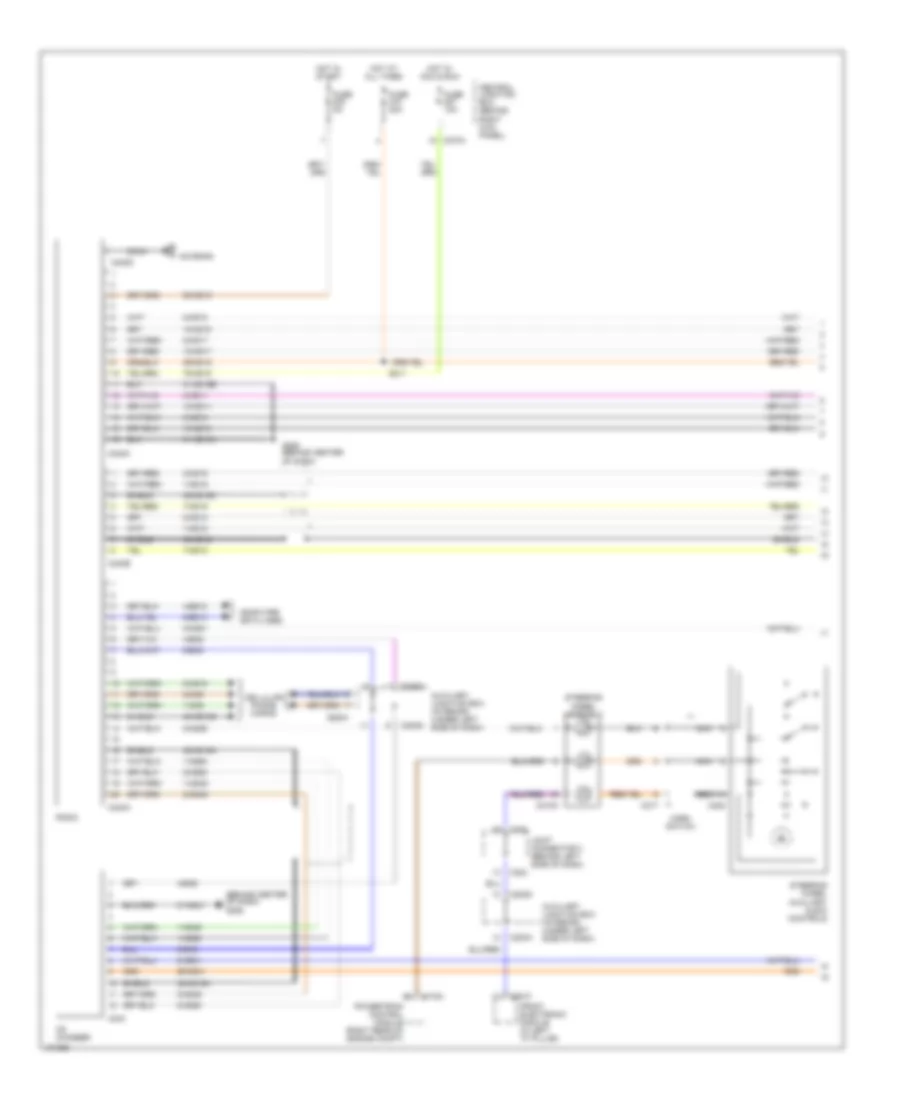 https://portal-diagnostov.com/license.html
Automotive Electricians Portal FZCO
Automotive Electricians Portal FZCO
https://portal-diagnostov.com/license.html
https://portal-diagnostov.com/license.html
Automotive Electricians Portal FZCO
Automotive Electricians Portal FZCOList of elements for Radio Wiring Diagram (1 of 2) for Lincoln LS 2001:
- (behind center of dash) g206
- 1-mc9
- 1-md12
- 1-md19
- 1-md49
- 1-md50
- 10-md10
- 10-md11
- 10-md17
- 10-md18
- 2-mc9
- 2-md12
- 2-md19
- 2-md49
- 2-md50
- 29-md15
- 29-md41
- 31-md15a
- 31-md15b
- 31-md41
- 4-ea6
- 4-ea8
- 4-eg10
- 48-md12
- 48-md15a
- 48-md15b
- 48-md15c
- 5-ea6
- 5-ea8
- 5-eg10
- 50-md15
- 7-md12
- 7-md19
- 75-md15
- 8-md10
- 8-md11
- 8-md15
- 8-md17
- 8-md18
- 8-md26
- 8-md51
- Antenna
- Auxiliary junction box (interior) (under left side of dash)
- C175a
- C201f
- C208
- C217
- C218a
- C224
- C240a
- C240b
- C240c
- C240d
- C243
- C270a
- C283a
- C283d
- Cd changer
- Cellular phone wiring
- Central junction box (behind right kick panel)
- Coax
- Computer data lines
- Front electronic module (in left "a" pillar)
- Fuse 10a
- Fuse 20a
- Fuse 5a
- G206 (behind center of dash)
- Horn switch
- Hot at all times
- Hot in acc & run
- Hot in start
- Joint connector 3 (behind left side of dash)
- Nca
- Powertrain control module (right rear of engine compt)
- Radio
- S211
- Shield
- Steering wheel assembly
- Steering wheel auxiliary audio controls
Radio Wiring Diagram (2 of 2) for Lincoln LS 2001
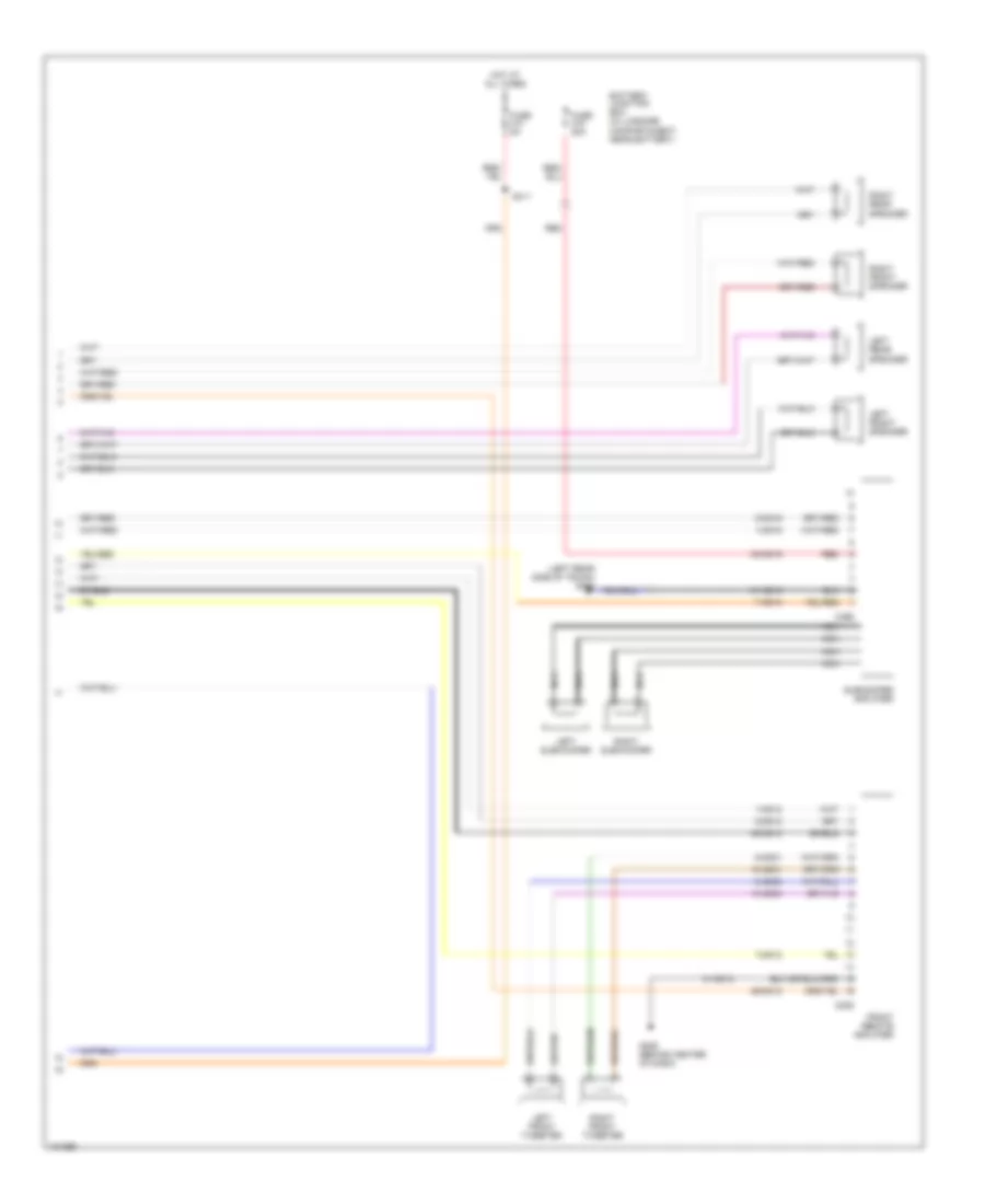 https://portal-diagnostov.com/license.html
Automotive Electricians Portal FZCO
Automotive Electricians Portal FZCO
https://portal-diagnostov.com/license.html
https://portal-diagnostov.com/license.html
Automotive Electricians Portal FZCO
Automotive Electricians Portal FZCOList of elements for Radio Wiring Diagram (2 of 2) for Lincoln LS 2001:
- (left rear side of trunk) g404
- 1-md12
- 1-md19
- 10-md30
- 10-md31
- 2-md12
- 2-md19
- 29-md12
- 30-md19
- 31-md12
- 31-md19
- 48-md12
- 7-md12
- 7-md19
- 8-md30
- 8-md31
- Battery junction box (in luggage compartmaent, near battery)
- C225
- C466
- Front remote amplifier
- Fuse 20a
- Fuse 5a
- G206 (behind center of dash)
- Hot at all times
- Left front speaker
- Left front tweeter
- Left rear speaker
- Left subwoofer
- Nca
- Red
- Right front speaker
- Right front tweeter
- Right rear speaker
- Right subwoofer
- S411
- Shield
- Subwoofer amplifier
SHIFT INTERLOCK
Shift Interlock Wiring Diagram, with IVD for Lincoln LS 2001
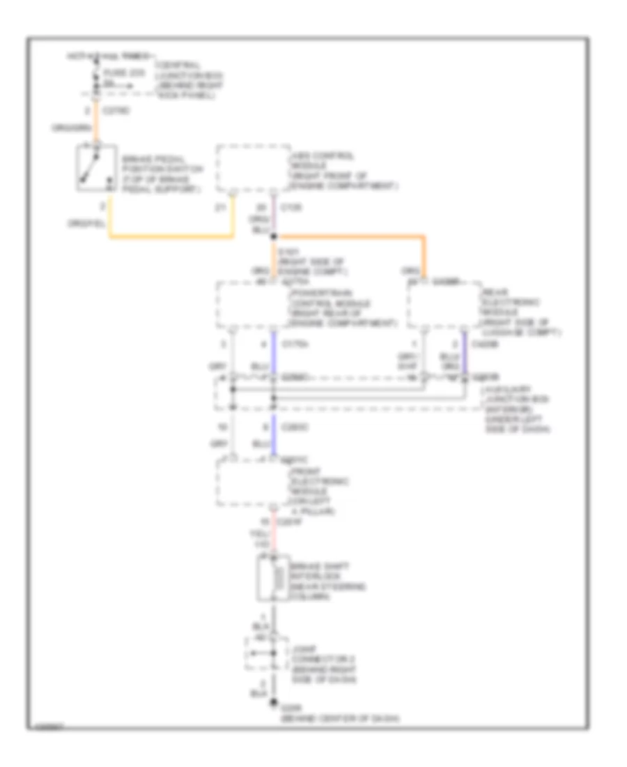 https://portal-diagnostov.com/license.html
Automotive Electricians Portal FZCO
Automotive Electricians Portal FZCO
https://portal-diagnostov.com/license.html
https://portal-diagnostov.com/license.html
Automotive Electricians Portal FZCO
Automotive Electricians Portal FZCOList of elements for Shift Interlock Wiring Diagram, with IVD for Lincoln LS 2001:
- Abs control module (right front of engine compartment)
- Auxiliary junction box (interior) (under left side of dash)
- Brake pedal position switch (top of brake pedal support)
- Brake shift interlock (near steering column)
- C135
- C175a
- C201c
- C201f
- C270d
- C283b
- C283c
- C420b
- Central junction box (behind right kick panel)
- Front electronic module (on left a pillar)
- Fuse 235 5a
- G206 (behind center of dash)
- Hot at all times
- Joint connector 2 (behind right side of dash)
- Powertrain control module (right rear of engine compartment)
- Rear electronic module (right side of luggage compt)
- S101 (right side of engine compt) c175a
Shift Interlock Wiring Diagram, without IVD for Lincoln LS 2001
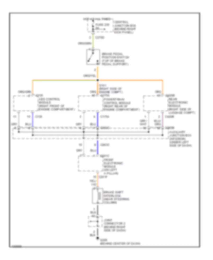 https://portal-diagnostov.com/license.html
Automotive Electricians Portal FZCO
Automotive Electricians Portal FZCO
https://portal-diagnostov.com/license.html
https://portal-diagnostov.com/license.html
Automotive Electricians Portal FZCO
Automotive Electricians Portal FZCOList of elements for Shift Interlock Wiring Diagram, without IVD for Lincoln LS 2001:
- Abs control module (right front of engine compartment)
- Auxiliary junction box (interior) (under left side of dash)
- Brake pedal position switch (top of brake pedal support)
- Brake shift interlock (near steering column)
- C135
- C175a
- C201c
- C201f
- C270d
- C283b
- C283c
- C420b
- Central junction box (behind right kick panel)
- Front electronic module (on left a pillar)
- Fuse 235 5a
- G206 (behind center of dash)
- Hot at all times
- Joint connector 2 (behind right side of dash)
- Powertrain control module (right rear of engine compartment)
- Rear electronic module (right side of luggage compt)
- S101 (right side of engine compt) c175a
STARTING/CHARGING
Charging Wiring Diagram for Lincoln LS 2001
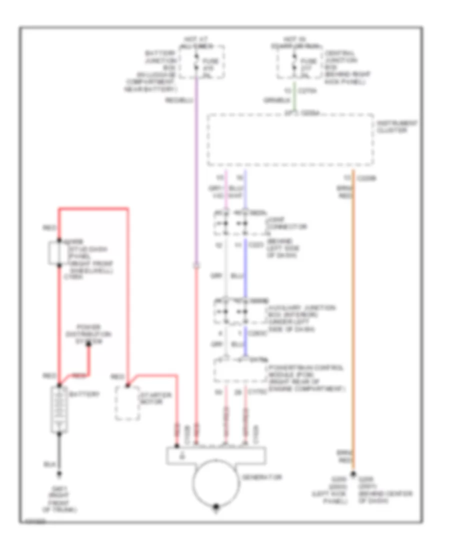 https://portal-diagnostov.com/license.html
Automotive Electricians Portal FZCO
Automotive Electricians Portal FZCO
https://portal-diagnostov.com/license.html
https://portal-diagnostov.com/license.html
Automotive Electricians Portal FZCO
Automotive Electricians Portal FZCOList of elements for Charging Wiring Diagram for Lincoln LS 2001:
- Auxiliary junction box (interior) (under left side of dash)
- Battery
- Battery junction box (in luggage compartment, near battery)
- C102a
- C102b
- C175a
- C175c
- C195a
- C195b
- C220a
- C220b
- C223
- C270a
- C283c
- C283d
- Central junction box (behind right kick panel)
- Fuse 5a
- G200 (2000) (left kick panel)
- G206 (2001) (behind center of dash)
- G401 (right front of trunk)
- Generator
- Hot at all times
- Hot in start or run
- Instrument cluster
- Joint connector (behind left side of dash)
- Power distribution system
- Powertrain control module (pcm) (right rear of engine compartment)
- Red
- Starter motor
- Stud dash panel (right front wheelwell)
Starting Wiring Diagram for Lincoln LS 2001
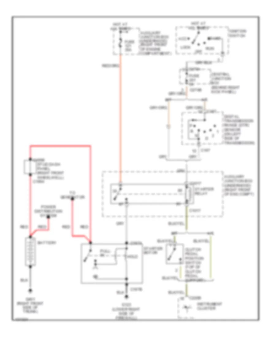 https://portal-diagnostov.com/license.html
Automotive Electricians Portal FZCO
Automotive Electricians Portal FZCO
https://portal-diagnostov.com/license.html
https://portal-diagnostov.com/license.html
Automotive Electricians Portal FZCO
Automotive Electricians Portal FZCOList of elements for Starting Wiring Diagram for Lincoln LS 2001:
- A/t
- Acc
- Auxiliary junction box (underhood) (right front of eng compt)
- Auxiliary junction box (underhood) (right front of engine compartment)
- Battery
- C1017
- C167
- C195a
- C195b
- C197a
- C197b
- C220b
- C270a
- C270b
- Central junction box (behind right kick panel)
- Clutch pedal position switch (top of clutch pedal support)
- Digital transmission range (dtr) sensor (on left side of transmission)
- Fuse 30a
- Fuse 5a
- G123 (lower right side of firewall)
- G401 (right front side of trunk)
- Hold
- Hot at all times
- Ignition switch
- Instrument cluster
- Lock
- M/t
- Off
- Power distribution system
- Pull- in
- Red
- Run
- Start
- Starter motor
- Starter relay
- Stud dash panel (right front wheelwell)
- To generator
SUPPLEMENTAL RESTRAINTS
Supplemental Restraints Wiring Diagram for Lincoln LS 2001
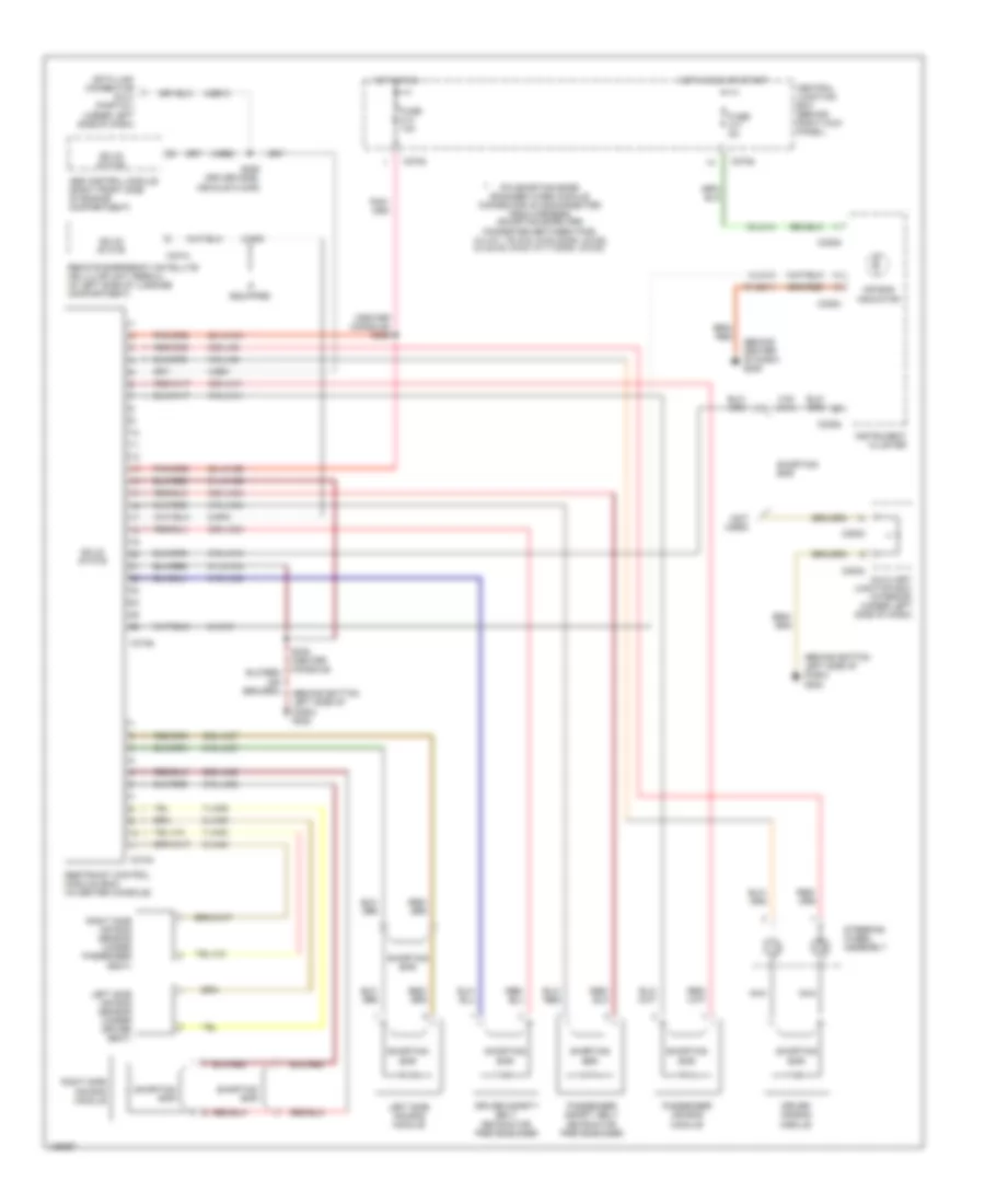 https://portal-diagnostov.com/license.html
Automotive Electricians Portal FZCO
Automotive Electricians Portal FZCO
https://portal-diagnostov.com/license.html
https://portal-diagnostov.com/license.html
Automotive Electricians Portal FZCO
Automotive Electricians Portal FZCOList of elements for Supplemental Restraints Wiring Diagram for Lincoln LS 2001:
- (behind bottom left side of dash) g202
- (behind center of dash) g206
- (center console) s306
- (not used)
- 15-ja14
- 20-ja10a
- 20-ja10b
- 30s-ja11
- 30s-ja33
- 30s-ja34
- 30s-ja37
- 30s-ja38
- 30s-ja8
- 31-ja10a
- 31-ja10b
- 31s- ja14
- 31s-ja11
- 31s-ja14
- 31s-ja33
- 31s-ja34
- 31s-ja37
- 31s-ja38
- 31s-ja8
- 4-ee1
- 4-ee10
- 4-ee6
- 7-ja39
- 7-ja40
- 8-gp8
- 8-ja13
- 9-ja39
- 9-ja40
- 91-gg11
- Abs control module (right front side of engine compartment)
- Air bag indicator
- Auxiliary junction box (interior) (under left side of dash)
- C220a
- C220b
- C270a
- C270e
- C283b
- C283d
- C310a
- C310b
- C401b
- Central junction box (behind right kick panel)
- Data link connector (dlc) (partial) (under left side of dash)
- Driver air bag module
- Driver safety belt retractor pretensioner
- Fuse 10a
- Fuse 5a
- Hot in run
- Hot in run or start
- If equipped
- Instrument cluster
- Left side air bag module
- Left side air bag sensor (under driver seat)
- Nca
- Passenger air bag module
- Passenger safety belt retractor pretensioner
- Pin shorting bars engaged when module connector is disconnected from harness (shorting bars are connected between pins: 3-4, 6-7, 15-16 & 18-22 conn. c310a 2-3 & 5-6, 8-9 & 10-11 conn. c310b)
- Remote emergency satellite cellular unit (rescu) (in left side of luggage compartment)
- Restraint control module (rcm) (in center console)
- Right side air bag module
- Right side air bag sensor (under passenger seat)
- S206 (driver side, vehicle floor)
- S305 (center console)
- Shorting bar
- Solid state
- Steering wheel assembly
TRANSMISSION
A/T Wiring Diagram for Lincoln LS 2001
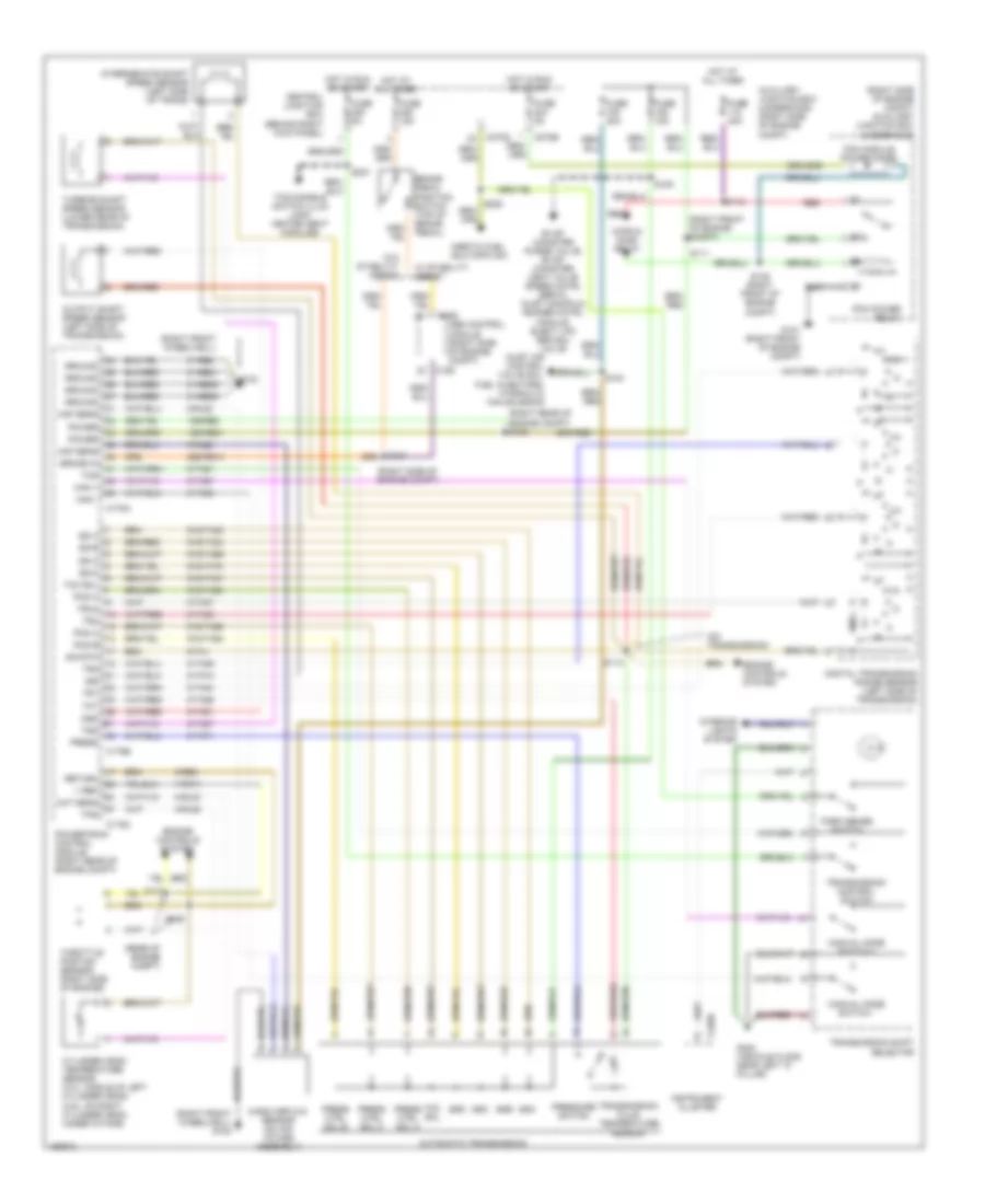 https://portal-diagnostov.com/license.html
Automotive Electricians Portal FZCO
Automotive Electricians Portal FZCO
https://portal-diagnostov.com/license.html
https://portal-diagnostov.com/license.html
Automotive Electricians Portal FZCO
Automotive Electricians Portal FZCOList of elements for A/T Wiring Diagram for Lincoln LS 2001:
- (on transmission)
- (rear of engine compt)
- (right front of engine compt)
- (right front wheelwell)
- (right front wheelwell) g102
- (right rear of engine compt) s102
- (right side of engine compt)
- (right side of engine compt) auxiliary junction box (underhood)
- 15s-re21
- 15s-re8
- 29s-re13
- 3/4
- 31-re21
- 31-re25
- 31-re26
- 31-re8
- 7-rn11
- 8-rj22
- 8-rj28
- 8-rj33
- 8-ta21
- 8-ta26
- 8-ta27
- 8-ta37
- 8-ta38
- 8-ta39
- 8-ta40
- 8-ta51
- 8-ta67
- 8-ta68
- 8-ta71
- 8-ta74
- 9-re8
- 9-rj22
- 9-ta1
- 91s-ta23
- 91s-ta24
- 91s-ta47
- 91s-ta63
- 91s-ta64
- 91s-ta65
- 91s-ta69
- 91s-ta70
- Abs control module (right side of engine compt)
- Automatic transmission
- Auxiliary junction box (underhood) (right side of engine compt)
- Brake in
- Brake pedal position switch (top of brake pedal)
- C155
- C175a
- C175b
- C175c
- C220b
- C270b
- C270d
- Central junction box (behind right kick panel)
- Cht sens
- Cops & ho2s relay
- Cylinder head temperature sensor (3.0l: middle of left cylinder head) (3.9l: on right cylinder head, under intake)
- Digital transmission range sensor (left side of transmission)
- Engine controls system
- Evap canister purge valve, evap canister vent valve speed cntrl servo, inlet manifold runner cntrl module, elect vac reg sol valve
- Fuse 15a
- Fuse 20a
- Fuse 40a
- Fuse 5a
- G101 (right front of engine compt)
- G102
- G302 (vehicle floor, near left "c" pillar)
- Ground
- Hot at all times
- Hot in run or start
- Inertia fuel shutoffc sw
- Inlet air control valve sol, fuel injectors, hydraulic fan solenoid
- Instrument cluster
- Interior lights system
- Intermediate shaft speed sensor (left side of trans)
- Iss
- Maf sens
- Man +
- Man -
- Manual mode switch +
- Manual mode switch -
- Mass airflow sensor (on air intake assembly)
- Oss tss
- Output shaft speed sensor (left side of transmission)
- Park sense switch
- Pcm module power diode
- Pcm power relay
- Pcs b
- Pcs c
- Power
- Powertrain control module (right rear of engine compt)
- Press
- Press ctrl sol a
- Press ctrl sol b
- Press ctrl sol c
- Pressure switch
- Red
- Return
- S101
- S104
- S105
- S110
- S111
- S112
- S126
- S127
- S138 (right front of engine compt)
- S207
- Sig rtn
- Ss a
- Ss b
- Ss c
- Ss d
- Ssa
- Ssb
- Ssc
- Ssd
- Tcc sol
- Tcc sol pcs a
- Tcs
- Tcs disable switch illum lamp, heated seat modules
- Tft
- Throttle postion sensor (right side of engine)
- Tps
- Tr1
- Tr2
- Tr3a
- Tr4
- Transmission control switch
- Transmission fluid temperature sensor
- Transmission shift selector
- Turbine shaft speed sensor (lower rear of transmission)
- V ref
- W/ stability assist
- W/o stability assist
TRUNK, TAILGATE, FUEL DOOR
Trunk, Tailgate, Fuel Door Wiring Diagram for Lincoln LS 2001
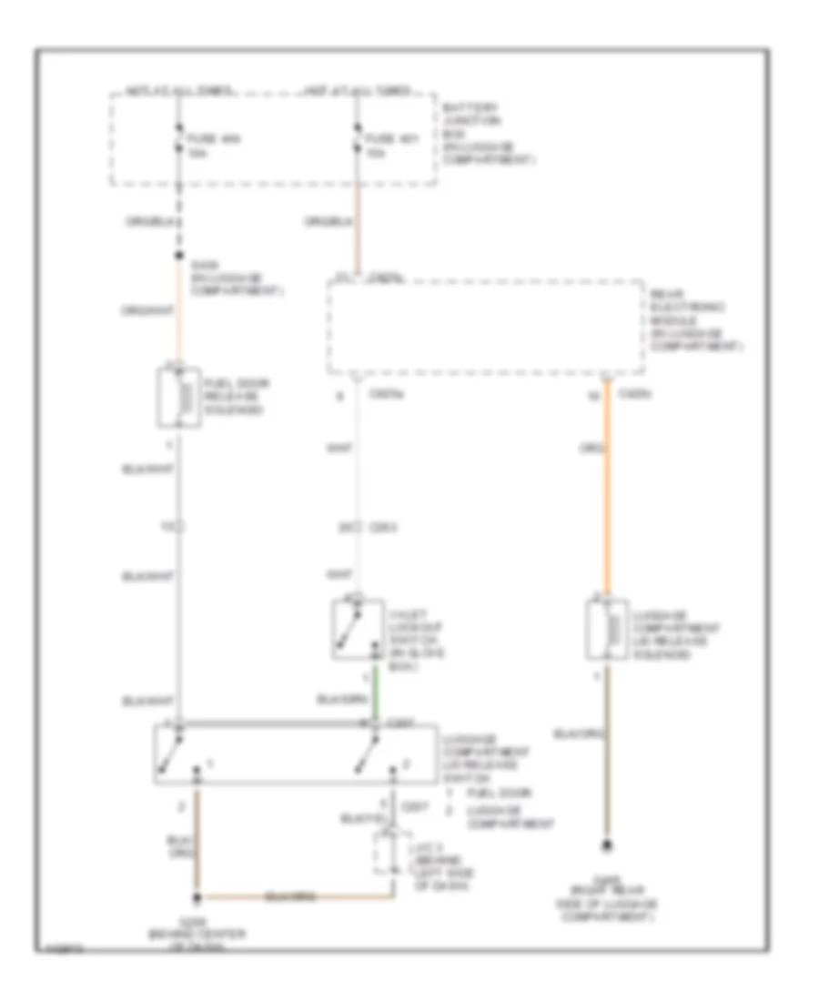 https://portal-diagnostov.com/license.html
Automotive Electricians Portal FZCO
Automotive Electricians Portal FZCO
https://portal-diagnostov.com/license.html
https://portal-diagnostov.com/license.html
Automotive Electricians Portal FZCO
Automotive Electricians Portal FZCOList of elements for Trunk, Tailgate, Fuel Door Wiring Diagram for Lincoln LS 2001:
- (behind center of dash)
- 10a
- 15a
- Battery junction box (in luggage compartment)
- C207
- C263
- C420a
- C420c
- Fuel door
- Fuel door release solenoid
- Fuse 401
- Fuse 404
- G206
- G405 (right rear side of luggage compartment)
- Hot at all times
- J/c 3 (behind left side of dash)
- Luggage compartment
- Luggage compartment lid release solenoid
- Luggage compartment lid release switch
- Rear electronic module (in luggage compartment)
- S430 (in luggage compartment)
- Valet lockout switch (in glove box)
WARNING SYSTEMS
Warning Systems Wiring Diagram for Lincoln LS 2001
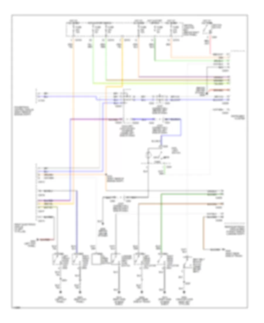 https://portal-diagnostov.com/license.html
Automotive Electricians Portal FZCO
Automotive Electricians Portal FZCO
https://portal-diagnostov.com/license.html
https://portal-diagnostov.com/license.html
Automotive Electricians Portal FZCO
Automotive Electricians Portal FZCOList of elements for Warning Systems Wiring Diagram for Lincoln LS 2001:
- (behind center of dash) g206
- Auxiliary junction box (interior) (under left side of dash)
- C103
- C175a
- C201a
- C201c
- C201e
- C201f
- C205
- C220a
- C220b
- C220c
- C223
- C224
- C250
- C262
- C270a
- C270c
- C270d
- C283a
- C283c
- C283d
- C420b
- C420c
- C420d
- C525
- C609
- C704
- C804
- Central junction box (behind right kick panel)
- Front electronic module (in left "a" pillar)
- Fuse 10a
- Fuse 20a
- Fuse 5a
- G200 (left kick panel)
- G203 (right kick panel)
- G206 (behind center of dash)
- G300 (vehicle floor near left 'c' pillar)
- G313 (right side of rear shelf)
- G404 (left rear side of trunk)
- G405 (right rear side of trunk)
- Head
- Hot at all times
- Hot in start or run
- Ignition switch
- Instrument cluster
- Joint connector 2 (behind right side of dash)
- Joint connector 3 (behind left side of dash)
- Joint connector 4 (behind left side of dash)
- Left front door lock unit c525
- Left rear door lock actuator c704
- Luggage compart- ment ajar switch
- Main light switch
- Off
- Oil pres- sure switch
- Park
- Powertrain control module (right rear of engine compt)
- Rear electronic module (rem) (in right side of luggage compt)
- Right front door lock unit c609
- Right rear door lock actuator c804
- S153 (right rear of engine compt)
- S397
- S504
- Seat belt buckle switch (under driver seat)
WIPER/WASHER
Wiper/Washer Wiring Diagram for Lincoln LS 2001
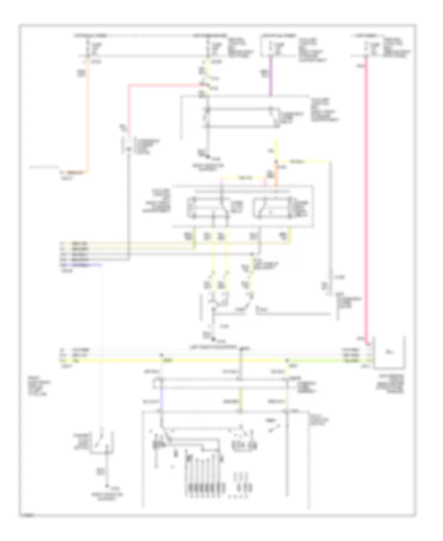 https://portal-diagnostov.com/license.html
Automotive Electricians Portal FZCO
Automotive Electricians Portal FZCO
https://portal-diagnostov.com/license.html
https://portal-diagnostov.com/license.html
Automotive Electricians Portal FZCO
Automotive Electricians Portal FZCOList of elements for Wiper/Washer Wiring Diagram for Lincoln LS 2001:
- (left radiator support)
- (right radiator support)
- .249k
- .402k
- .953k
- 1.910k
- 2.670k
- Auxiliary junction box (right front of engine compartment)
- C1026
- C125
- C144
- C201a
- C201b
- C201f
- C202
- C218b
- C270c
- C270e
- C914
- Central junction box (behind right kick panel)
- Front electronic module (in left "a" pillar)
- Fuse 10a
- Fuse 30a
- Fuse 3a
- Fuse 5a
- G108
- G109
- High
- Hot at all times
- Hot in run
- Hot in run or acc
- Int
- Low
- Max
- Min
- Mist
- Multi- function switch
- Off
- Park
- Pnk
- Rain sensor module (rear center of roof panel opening)
- Run
- S115 (left side of eng compt)
- S140
- S152
- S203
- S204
- S209
- Steering wheel assembly
- Wash
- Washer fluid level switch
- Windshield washer pump motor
- Windshield wiper motor
- Windshield wiper relay
- Wiper hi/low relay
- Wiper run/ park relay

 Čeština
 Dansk
Dansk Deutsch
 Ελληνικά
 English
 English
 Español
 Suomi
Suomi Français
 Français
 עברית
עברית Hrvatski
 Magyar
 Italiano
 日本語
日本語 Nederlands
 Polski
 Português
 Português
 Română
 Русский
 Slovenčina
 Slovenščina
 Svenska
 Türkçe
 中文 (中国)
