Land Rover Defender 90 1995 - 1995 ELECTRICAL COMPONENT LOCATOR Defender & Range Rover - 3.9L & 4.2L
Land Rover Defender 90 1995 - BUZZERS, RELAYS & TIMERS
NOTE: Defender service information is similar to Range Rover service information. Land Rover does not provide Defender specific service information.
Land Rover Defender 90 1995 BUZZERS, RELAYS & TIMERS
Description (Components) Component Locations ABS Load Relay (K101) Beneath Left Front Seat. See Fig. 42 . ABS Pump Relay (K102) Beneath Left Front Seat. See Fig. 42 . ABS Warning Relay (K103) Beneath Left Front Seat. See Fig. 43 . Accessory Relay (K174) Behind Left Footwell Trim Panel. See Fig. 18 . A/C Logic Relay (K170) Behind Right Footwell Trim Panel. See Fig. 37 . Air Suspension Compressor Relay (K156) Beneath Right Front Seat. See Fig. 46 . Air Suspension Delay Relay (K158) Beneath Right Front Seat. See Fig. 46 . Alarm Relay (K208) Behind Right Side Of Fascia. See Fig. 34 . Auxiliary Lamps Relay (K105) Left Side Behind Footwell Trim Panel. See Fig. 35 . Blower Motor Relay (K188) Behind Right Side Of Fascia. See Fig. 30 . Bulb Check Relay (K173) Behind Right Side Of Fascia On Bracket. See Fig. 36 . Compressor Clutch Relay (K108) Right Side Behind Footwell Trim Panel. See Fig. 36 and Fig. 37 . Condenser Fan Relay (K109) Right Side Behind Footwell Trim Panel. See Fig. 36 . Cruise Control Lockout Relay (K110) Right Side Behind Footwell Trim Panel. See Fig. 35 . Engine Control Load Relay (K116) Behind Right Footwell Trim Panel. See Fig. 37 . Fuel Pump Relay (K119) Beneath Right Front Seat. See Fig. 37 . Front Wiper Relay (K185) Behind Right Footwell Trim Panel. See Fig. 37 . Heated Front Window Relay (K121) Near Steering Column Above Lower Dash Panel. See Fig. 35 . Heated Rear Window Relay (K122) Near Steering Column Above Lower Dash Panel. See Fig. 19 . Horn Relay (K189) Behind Left Footwell Trim Panel. See Fig. 18 . Ignition Load Relay (K127) Near Steering Column Above Lower Dash Panel. See Fig. 37 . Interlock Relay 1 (K153) Behind Right Side Of Fascia. See Fig. 34 . Interlock Relay 2 (K151) Behind Right Side Of Fascia. See Fig. 34 . Left Seat Heat Relay (K129) In Center Console Beneath Cubby Box Liner. Left Seat Power Relay (K113) Beneath Left Front Seat. Power Wash Relay (K182) Behind Left Side Of Fascia On Bracket. See Fig. 35 . Rear Wiper Relay (K183) Behind Left Footwell Trim Panel. See Fig. 18 . Refrigerator Relay (K148) Right Side Of Luggage Compartment. Right Horn Relay (K134) Behind Right Side Of Front Grille. Right Seat Heat Relay (K135) In Center Console Beneath Cubby Box Liner. See Fig. 47 . Right Seat Power Relay (K131) Beneath Right Front Seat. See Fig. 47 . Starter Solenoid Relay (K137) Near Steering Column Above Lower Dash Panel. See Fig. 36 . Sunroof Load Relay (K138) Left Side Behind Trim Panel. See Fig. 35 . Theft Alarm Relay (K159) Behind Driver's Side Of Dash. See Fig. 18 . Transfer Box Warning Relay (K186) Behind Right Side Of Fascia. See Fig. 34 . Transmission Range Selector Illumination Relay (K104) Near Steering Column Above Lower Dash Panel. See Fig. 34 . Warning Lamp Relay (K155) Beneath Right Front Seat. See Fig. 46 .
Land Rover Defender 90 1995 - CIRCUIT PROTECTION DEVICES
Land Rover Defender 90 1995 CIRCUIT PROTECTION DEVICES
Component Component Locations Air Recirculation Solenoid In-Line Fuse (P138) Behind Right Side Of Fascia. See Fig. 32 . Air Suspension In-Line Fuse (P123) Beneath Right Front Seat. Air Suspension In-Line Maxi Fuse (P122) Beneath Right Front Seat. See Fig. 46 . Driver Underseat Fuse Box (P108) Beneath Driver Seat. Engine Compartment Fuse Box (P125) Right Front Of Engine Compartment. See Fig. 9 . Fascia Fuse Box (P126) Behind Left Side Of Fascia Left Of Steering Column. See Fig. 18 . Fusible Link (P119) Right Side Of Engine Compartment Behind Battery. See Fig. 9 . Heated Front Window Fuse Block (P114) Near Steering Column Above Lower Dash Panel. See Fig. 31 . Heated Front Window In-Line Maxi-Fuse (P139) Right Front Of Engine Compartment Behind Battery. See Fig. 9 . Passenger Underseat Fuse Box (P116) Beneath Front Passenger Seat. See Fig. 47 . Refrigerator Fuse - Control (P141) Right Side Of Luggage Compartment. Refrigerator Fuse - Power (P121) Right Side Of Luggage Compartment. Satellite Fuse Box 1 (P127) Behind Left Side Of Fascia On Fascia Fuse Box. See Fig. 18 . Satellite Fuse Box 2 (P128) Behind Left Side Of Fascia On Fascia Fuse Box. See Fig. 18 .
Land Rover Defender 90 1995 - CONTROL UNITS
Land Rover Defender 90 1995 CONTROL UNITS
Component Component Locations ABS Booster Unit (Z103) Left Rear Corner Of Engine Compartment. See Fig. 2 . ABS ECU (Z108) Beneath Left Front Seat. See Fig. 42 . ABS Pressure Switch Unit (Z104) Driver's Side Of Engine Compartment. See Fig. 2 . Air Bag Diagnostic Control Module (Z151) Beneath Center Console. See Fig. 29 . Air Suspension ECU (Z165) Beneath Right Front Seat. See Fig. 46 . Blower Resistor Unit (Z112) Inside Heater Unit Beneath Center Of Dash. See Fig. 30 . Central Locking Control Unit (Z113) Near Steering Column Above Lower Dash Panel. See Fig. 33 . Cruise Control Diode (Z186) Behind Right Side Of Fascia. See Fig. 35 . Cruise Control ECU (Z121) Near Steering Column Above Lower Dash Panel. Daytime Running Lights Control Unit (Z122) Left Side Behind Footwell Trim. EGR Valve Control Module (Z149) Behind Right Side Of Fascia. See Fig. 33 . Engine Control Module (ECM) (Z132) Beneath Right Front Seat. See Fig. 33 . Fan Control Module (Z118) Beneath Right Front Seat. See Fig. 37 . Flasher Unit (Z128) Driver's Side Above Lower Dash Panel. See Fig. 19 . Fuel Pump Module (Z134) Top Of Fuel Tank. See Fig. 51 . Glow Plug Timer Unit (Z135) Right Front Of Engine Compartment Behind Battery. See Fig. 9 . Ignition Control Module (Z139) Front Center Of Engine Attached To Distributor. See Fig. 6 . Left Headlight Level Unit (Z145) Behind Left Headlight. Memory Seat ECU (Z146) Underside Of Driver's Seat. See Fig. 44 . Multi-Function Unit (MFU) (Z148) Behind Left Side Of Fascia On Fascia Fuse Box. See Fig. 19 . Multi-Port Fuel Injection Fault Display Unit (Z133) Beneath Right Front Seat. See Fig. 47 . Right Headlight Level Unit (Z155) Behind Right Headlight. Service Reminder Unit (Z126) Beneath Right Front Seat. See Fig. 47 . Speed Trip Module (Z164) Right Side Behind Footwell Trim Panel. See Fig. 35 . Subwoofer Control (X232) Center Of Fascia. Sunroof Control Unit (Z162) Front Center Of Roof. See Fig. 30 . Theft Alarm Unit (Z163) Behind Driver's Side Of Dash. See Fig. 34 . Window Lift ECU (Z147) Behind Right Side Of Fascia On Bracket. See Fig. 33 .
Land Rover Defender 90 1995 - SENDING UNITS & SENSORS
Land Rover Defender 90 1995 SENDING UNITS & SENSORS
Component Component Locations Alarm Sensor (X213) Front Center Of Roof. See Fig. 29 . EGR Valve Position Sensor (X218) Left Side Of Engine. Engine Coolant Temperature Gauge Sensor (X114) Top Center Of Engine On Intake Manifold. See Fig. 4 . Engine Coolant Temperature Sensor (X126) Top Center Of Engine On Intake Manifold. See Fig. 4 . Engine Fuel Temperature Sensor (X128) Front Center Of Engine. See Fig. 4 . Fore-Aft Sensor (X196) Underside Of Left Front Seat. See Fig. 45 . Front Height Sensor (X194) Underside Of Left Front Seat. See Fig. 45 . Left Front Height Sensor (X205) Behind Left Front Wheel. See Fig. 50 . Left Front Wheel Speed Sensor (X137) Behind Left Front Wheel. See Fig. 15 . Left Heated Oxygen Sensor (X139) Lower Left Side Of Engine Compartment. See Fig. 14 . Left Rear Height Sensor (X206) Behind Left Rear Wheel. See Fig. 49 . Left Rear Wheel Speed Sensor (X140) Behind Left Rear Wheel. See Fig. 15 . Mass Air Flow Sensor (X105) Left Side Of Engine. See Fig. 3 . Rear Height Sensor (X195) Underside Of Left Front Seat. See Fig. 45 . Recline Sensor (X197) Underside Of Left Front Seat. See Fig. 45 . Right Front Height Sensor (X207) Behind Right Front Wheel. See Fig. 50 . Right Front Wheel Speed Sensor (X158) Behind Right Front Wheel. See Fig. 15 . Right Heated Oxygen Sensor (X160) Lower Right Side Of Engine Compartment. See Fig. 13 . Right Rear Height Sensor (X208) Behind Right Rear Wheel. See Fig. 49 . Right Rear Wheel Speed Sensor (X161) Behind Right Rear Wheel. See Fig. 15 . Throttle Position Sensor (X171) Top Center Of Engine. See Fig. 4 . Vehicle Speed Sensor (X190) On Left Frame Rail Beneath Center Of Passenger Compartment. See Fig. 16 .
Land Rover Defender 90 1995 - MOTORS
Land Rover Defender 90 1995 MOTORS
Component Component Locations ABS Hydraulic Pump (M102) Driver's Side Of Engine Compartment Top Of Fender Well. See Fig. 2 . Air Suspension Compressor (M140) Beneath Right Side Of Vehicle. See Fig. 50 . Cruise Control Vacuum Pump (M103) Left Front Corner Of Engine Compartment On Fender Well. See Fig. 5 . Front Blower Motor (M101) Behind Right Side Of Fascia. See Fig. 32 . Front Window Wash Pump (M105) Passenger's Rear Corner Of Engine Compartment. See Fig. 14 . Front Wiper Motor (M107) Driver's Side Of Bulkhead Beneath Dash. Headlight Wash Pump (M110) Passenger's Rear Corner Of Engine Compartment. See Fig. 14 . Left Condenser Fan Motor (M113) Behind Front Grille. See Fig. 7 . Left Front Window Motor (M130) In Front Of Left Front Door. See Fig. 38 . Left Rear Window Motor (M116) Inside Respective Rear Door. See Fig. 41 . Rear Window Wash Pump (M119) Passenger's Rear Corner Of Engine Compartment. See Fig. 14 . Rear Wiper Motor (M120) Center Rear Of Roof. See Fig. 52 . Right Condenser Fan Motor (M121) Behind Front Grille. See Fig. 7 . Right Front Window Motor (M133) In Front Of Right Front Door. See Fig. 38 . Right Rear Window Motor (M124) Inside Respective Rear Door. See Fig. 41 . Seat Base Motor With Memory (M126) Underside Of Respective Front Seat. See Fig. 44 and Fig. 48 . Seat Base Motor Without Memory (M126) Underside Of Respective Front Seat. See Fig. 43 . Seat Height (Front) Motor With Memory (M127) Underside Of Respective Front Seat. See Fig. 44 and Fig. 48 . Seat Height (Front) Motor Without Memory (M127) Underside Of Respective Front Seat. See Fig. 43 . Seat Height (Rear) Motor With Memory (M128) Underside Of Respective Front Seat. See Fig. 44 and Fig. 48 . Seat Height (Rear) Motor Without Memory (M128) Underside Of Respective Front Seat. See Fig. 43 . Seat Recline Motor With Memory (M129) Underside Of Respective Front Seat. See Fig. 44 and Fig. 48 . Seat Recline Motor Without Memory (M129) Underside Of Respective Front Seat. See Fig. 43 . Sunroof Motor (M131) Front Center Of Roof. See Fig. 30 .
Land Rover Defender 90 1995 - SOLENOIDS & SOLENOID VALVES
Land Rover Defender 90 1995 SOLENOIDS & SOLENOID VALVES
Component Component Locations Air Recirculation Solenoid (K123) Behind Right Side Of Fascia Left Side Of Heater Evaporator Unit. See Fig. 30 . Brake Switch Vent Valve (X112) On Brake Pedal Support Above Lower Dash Panel. EGR Control Solenoid (K171) Left Front Corner Of Engine Compartment. See Fig. 5 . Evaporative Emission Canister Purge Valve (K132) Right Side Of Engine Compartment. See Fig. 13 . Fuel Flap Actuator (M108) Right Side Of Luggage Compartment. See Fig. 53 . Fuel Shut-Off Solenoid (K111) Right Side Of Engine On Injector Pump. Idle Air Control Valve (M112) Top Rear Of Engine. See Fig. 11 . Ignition Key Lock Solenoid (K191) Top Of Steering Column. See Fig. 22 . Left Front Door Lock Actuator (M114) Inside Respective Front Door Near Lock Switch. See Fig. 39 . Left Mirror Actuator (M115) Top Front Of Left Front Door. Left Rear Door Lock Actuator (M117) Inside Respective Rear Door. See Fig. 41 . Right Front Door Lock Actuator (M122) Inside Respective Front Door Near Lock Switch. See Fig. 39 . Right Mirror Actuator (M123) Top Front Of Right Front Door. Right Rear Door Lock Actuator (M125) Inside Respective Rear Door. See Fig. 41 . Starter Solenoid (K136) Lower Right Side Of Engine. See Fig. 12 . Tailgate Lock Actuator (M132) Lower Center Of Rear Screen. See Fig. 53 . Transfer Box Solenoid (K154) In Transfer Box. Water Valve (K206) Right Rear Corner Of Engine Compartment. See Fig. 14 .
Land Rover Defender 90 1995 - SWITCHES
Land Rover Defender 90 1995 SWITCHES
Component Component Locations A/C Dual Pressure Switch (X102) Right Side Of Engine Compartment. See Fig. 13 . Air Supply Selector Switch (X180) Center Of Fascia. See Fig. 27 . Air Suspension Down Switch (X211) Center Of Fascia. See Fig. 26 . Air Suspension Inhibit Switch (X209) Center Of Fascia. See Fig. 26 . Air Suspension Up Switch (X210) Center Of Fascia. See Fig. 26 . Alarm Hood Switch (X212) Passenger's Rear Corner Of Engine Compartment. See Fig. 13 . Automatic Transmission Oil Temperature Switch (X108) Left Front Of Engine Compartment. See Fig. 9 . Auxiliary Lamps Switch (X109) Center Of Fascia. See Fig. 25 . Brake Fluid Level Switch (X111) Driver's Rear Corner Of Engine Compartment Top Of Brake Fluid Reservoir. See Fig. 1 . Clutch Pedal Position Switch (X200) Near Steering Column Above Lower Dash Panel. Compressor Clutch Cut-Out Switch (X259) Right Front Of Engine. Condenser Fan Coolant Temperature Switch (X113) Top Center Of Engine On Thermostat Housing. See Fig. 6 . Cruise Control Switch (X115) Center Of Fascia. See Fig. 25 . Direction Indicator Switch (X116) Top Of Steering Column. See Fig. 22 . Disable Switch (X203) Beneath Right Front Seat. See Fig. 46 . Fan Speed Switch (X179) Center Of Fascia. See Fig. 27 . Front A/C Evaporator Temperature Switch (X101) Left Side Of Fascia Left Of Steering Column. See Fig. 24 . Front A/C Switch (X225) Center Of Fascia. See Fig. 27 . Front Wipe/Wash Switch (X124) Top Of Steering Column. See Fig. 21 . Fuel Flap Release Switch (X125) Top Left Side Of Fascia Left Of Steering Column. See Fig. 20 . Handbrake Switch (X191) On Handbrake Lever Beneath Cubby Box Liner. See Fig. 29 . Hazard Switch (X220) Center Of Fascia. See Fig. 25 . Heated Front Window Switch (X131) Center Of Fascia. See Fig. 25 . Heated Rear Window Switch (X132) Center Of Fascia. See Fig. 25 . Heated Washer Jets Thermoswitch (X133) Behind Right Side Of Front Grille. See Fig. 7 . Hood Switch (X110) Left Rear Corner Of Engine Compartment. See Fig. 1 . Horn Switches (X258) In Steering Wheel. See Fig. 21 . Ignition Switch (X134) In Steering Column Behind Trim. See Fig. 22 . Inertia Fuel Shut-Off Switch (X135) Beneath Left Front Seat. See Fig. 14 . Interior Lamps Switch (X136) Center Of Fascia. See Fig. 26 . Key-Barrel Switch (X230) Top Of Steering Column On Ignition Switch. See Fig. 22 . Key-In Switch (X229) Top Of Steering Column On Ignition Switch. See Fig. 22 . Left Front Door Handle Switch (X138) Inside Respective Front Door At Door Handle. Left Front Door Key Switch (X201) Inside Respective Front Door Near Lock Switch. See Fig. 40 . Left Front Door Switch (X150) Front Of Left Front Door Jamb. Left Front Seat Control Switch With Memory (X152) Right Side Of Left Front Seat. See Fig. 43 . Left Front Seat Control Switch Without Memory (X152) Right Side Of Left Front Seat. See Fig. 43 . Left Front Window Switch (X122) In Rear Of Center Console. See Fig. 27 . Left Maximum Cool Switch (X267) Behind Heater And A/C Control Panel. See Fig. 27 . Left Rear Door Switch (X142) Middle Of Respective Rear Door Jamb Area. See Fig. 40 . Left Rear Window Console Switch (X141) In Rear Of Center Console. See Fig. 28 . Left Rear Window Door Switch (X188) In Top Of Left Rear Door. See Fig. 41 . Left Seat Heat Switch (X143) In Rear Of Center Console. See Fig. 28 . Main Lighting Switch (X145) Top Of Steering Column. See Fig. 22 . Mirror Adjustment Switch (X146) Top Left Side Of Fascia Left Of Steering Column. See Fig. 20 . Oil Pressure Switch (X149) Front Right Side Of Engine Oil Pump Housing. See Fig. 8 . Park/Neutral Position Switch (X167) Beneath Vehicle On Left Side Of Transmission.. See Fig. 16 . Park Switch (X173) Beneath Center Console. Rear Fog Guard Lamps Switch (X154) Center Of Fascia. See Fig. 25 . Rear Window Wash Switch (X222) Top Left Side Of Fascia Left Of Steering Column. See Fig. 20 . Rear Window Wipe Switch (X221) Top Left Side Of Fascia Left Of Steering Column. See Fig. 20 . Rear Window Isolation Switch (X187) In Rear Of Center Console. See Fig. 28 . Reservoir Pressure Switch (X204) Beneath Left Side Of Vehicle. See Fig. 49 . Reverse Switch (X157) On Top Of Transmission. See Fig. 16 . Right Front Door Handle Switch (X159) Inside Respective Front Door At Door Handle. Right Front Door Key Switch (X202) Inside Respective Front Door Near Lock Switch. See Fig. 40 . Right Front Door Switch (X118) Front Of Right Front Door Jamb. Right Front Seat Control Switch (X121) Left Side Of Right Front Seat. See Fig. 48 . Right Front Window Switch (X151) In Rear Of Center Console. See Fig. 27 . Right Maximum Cool Switch (X268) Behind Heater And A/C Control Panel. See Fig. 27 . Right Rear Door Switch (X163) Middle Of Respective Rear Door Jamb Area. See Fig. 40 . Right Rear Window Console Switch (X162) In Rear Of Center Console. See Fig. 28 . Right Rear Window Door Switch (X189) In Top Of Rh Rear Door. See Fig. 41 . Right Seat Heat Switch (X164) In Rear Of Center Console. See Fig. 28 . Steering Wheel Cruise Switches (X266) In Steering Wheel. See Fig. 21 . Stop Lamp Switch (X168) On Brake Pedal Support Above Lower Dash Panel. See Fig. 20 . Sunroof Switch (X169) Front Center Of Roof. See Fig. 29 . Tailgate Switch (X170) Top Left Side Of Rear Window Opening. See Fig. 52 . Transfer Box Oil Temperature Switch (X174) In Transfer Box. See Fig. 16 . Transfer Box Position Switch (X175) Top Right Side Of Transfer Box. See Fig. 17 . Transmission Range Selector Switch (Z110) Beneath Center Console Near Transmission Range Selector. See Fig. 28 .
Land Rover Defender 90 1995 - MISCELLANEOUS
Land Rover Defender 90 1995 MISCELLANEOUS
Component Component Locations ABS Diode (Z192) Beneath Left Front Seat. See Fig. 42 . Air Supply Selector Diode (Z208) Behind Left Side Of Fascia Left Of Heater Evaporator Unit. See Fig. 24 . Air Suspension Disable Diode. (Z187) Beneath Right Front Seat. See Fig. 46 . Air Suspension Indicator Diode (Z188) Beneath Right Front Seat. See Fig. 45 . Air Suspension Resistor (K167) Beneath Right Front Seat. See Fig. 46 . Air Valve Block (K163) Beneath Right Side Of Vehicle. See Fig. 50 . CD Changer (Z114) Right Side Of Engine Compartment. Clock (Z117) Center Of Fascia. See Fig. 25 . Column Switch Illumination (B104) Top Of Steering Column On Ignition Switch. See Fig. 21 . Compressor Clutch (K107) Right Side Of Engine On Front Of A/C Compressor. See Fig. 12 . Condenser Fan Control Diode 1 (Z209) Behind Right Side Of Fascia. Condenser Fan Control Diode 2 (Z210) Behind Right Side Of Fascia. See Fig. 32 . Data Link Connectors (X127) Behind Right Side Of Fascia. See Fig. 31 . Daytime Running Lamps Diode (Z200) Behind Right Side Of Fascia Near Daytime Running Lamps Control Unit. Direction Indicator Diode 1 (Z212) Behind Instrument Cluster. See Fig. 23 . Direction Indicator Diode 2 (Z213) Behind Instrument Cluster. See Fig. 23 . Distributor (Z125) Front Center Of Engine. See Fig. 6 . ETC Valve Block (K162) Left Rear Corner Of Engine Compartment. See Fig. 2 . Fan Timer Diode (Z211) Behind Right Side Of Fascia. Fascia Cigar Lighter (B106) In Front Of Center Console. See Fig. 25 . Fuel Injectors (K141) Left Rear Of Engine Compartment. See Fig. 3 , Fig. 4 and Fig. 12 . Generator Left Front Corner Of Engine. See Fig. 12 . Generator Suppression Capacitor (Z182) Top Center Front Of Engine Generator. See Fig. 12 . GLow Plugs (P120) Right Side Of Engine Handbrake Diode (Z197) Beneath Center Console Near Handbrake Switch. Ignition Coil (Z140) MFI - V8 Left Side Of Engine Compartment On Inner Fender Well. See Fig. 6 . Ignition Coil Noise Suppressor (Z237) Left Front Of Engine Compartment On Ignition Coil. See Fig. 6 . Inhibit Indicator Diode (Z191) Fascia Wire Harness Near Air Suspension Inhibit Switch. Instrument Cluster (Z142) Top Left Side Of Fascia. See Fig. 23 . Instrument Illumination Rheostat (Z143) Top Left Side Of Fascia. See Fig. 21 . Interlock Diode 1 (Z189) Main Wire Harness Near Cruise Control ECU. Interlock Diode 2 (Z190) Main Wire Harness Near Cruise Control ECU. Left Antenna Amplifier (Z177) Right Rear Of Roof. See Fig. 55 . Left Front Speaker Crossover (Z224) In Front Of Left Front Door. Left Headlight (B116) Left Front Corner Of Engine Compartment. See Fig. 8 . Left Heated Washer Jet (B118) Mounted On The Hood. See Fig. 2 . Left Horn (K128) Behind Left Side Of Front Grille. See Fig. 5 . Left Repeater Lamp (B122) Left Front Of Vehicle. See Fig. 8 . Left Seat Power Relay Diode (Z223) Beneath Left Front Seat. Multiport Fuel Injection Ignition Resistor 1 (K115) Left Front Of Engine Compartment Near Ignition Coil. See Fig. 6 . Multiport Fuel Injection Ignition Resistor 2 (K168) Left Front Of Engine Compartment Near Ignition Coil. See Fig. 6 . NAS Diode (Z229) Behind Left Side Of Fascia Near Fascia Fuse Box.. Neutral Sense Resistor (K166) Gearbox Wire Harness Near C105. Phase Tap Resistor (K184) Top Center Front Of Engine On Generator. See Fig. 12 . Power Mirror Diode (Z185) Behind Right Side Of Fascia. Radio (Z111) Center Of Fascia. See Fig. 26 . Radio Amplifier (Z175) Right Side Of Luggage Compartment. See Fig. 54 . Rear Interior Roof Lamp (B124) Center Of Roof. Refrigerator (Z172) Rear Of Luggage Compartment. Reservoir Pressure Resistor (K169) Beneath Right Front Seat. See Fig. 45 . Right Antenna Amplifier (Z178) Right Rear Of Roof. See Fig. 55 . Right Front Inboard Brake Pad (B129) In Right Front Brake Caliper. See Fig. 15 . Right Front Speaker Crossover (Z225) In Front Of Right Front Door. Right Headlight (B130) Right Front Of Engine Compartment. See Fig. 8 . Right Heated Washer Jet (B132) Mounted On Hood. See Fig. 2 . Right Horn (K134) Left Front Corner Of Engine Compartment. See Fig. 5 . Right Rear Inboard Brake Pad (B135) In Right Rear Brake Caliper. See Fig. 15 . Right Repeater Lamp (B137) Rh Front Of Vehicle. See Fig. 8 . Right Seat Power Relay Diode (Z222) Beneath Left Front Seat. Rotary Coupler (Z119) Top Of Steering Column. See Fig. 22 . Starter (M134) Lower Right Side Of Engine. See Fig. 12 . Starter Relay Diode (Z158) Behind Right Footwell Trim Panel. See Fig. 36 . Stop Lamp Switch Suppressor (Z206) Behind Left Side Of Fascia Near Steering Column. See Fig. 20 . Subwoofer (K146) Right Rear Of Luggage Compartment. See Fig. 54 . Subwoofer Amplifier (Z176) Right Side Of Luggage Compartment. See Fig. 54 . Trailer Auxiliary Socket (X172) Behind Right Side Of Rear Bumper. See Fig. 51 . Transfer Box Solenoid Diode (Z232) Gearbox Wire Harness Near C105. Tune Select Resistor (K140) Behind Right Side Of Fascia. See Fig. 31 .
Land Rover Defender 90 1995 - CONNECTORS
Land Rover Defender 90 1995 CONNECTORS
Component Component Locations ABS Diagnostic Connector (X104) Beneath Left Front Seat. See Fig. 43 . Air Suspension Diagnostic Connector (Z167) Beneath Right Front Seat. See Fig. 45 . C100 (3-W) Right Front Of Engine Compartment On Engine Compartment Fuse Box. See Fig. 10 . C101 (4-W) Right Front Of Engine Compartment On Engine Compartment Fuse Box. See Fig. 10 . C102 (1-B) Left Rear Corner Of Engine Compartment. See Fig. 1 . C103 (3-B) Right Front Of Engine Compartment On Right Headlight. See Fig. 8 . C104 (3-B) Left Front Corner Of Engine Compartment On Left Headlight. See Fig. 8 . C105 (13-B) Left Rear Corner Of Engine Compartment. See Fig. 1 . C106 (2-B) Behind Right Side Of Front Bumper To Right Auxiliary Lamp. See Fig. 7 . C107 (2-B) Behind Left Side Of Front Bumper To Left Auxiliary Lamp. See Fig. 7 . C108 (1-B) Left Rear Corner Of Engine Compartment. See Fig. 1 . C109 (4-B)) Left Front Of Vehicle To Left Front Lamp Assembly. See Fig. 8 . C110 (4-B) Right Front Of Vehicle To Right Front Lamp Assembly. See Fig. 8 . C112 (3-W) Left Rear Corner Of Engine To Left Heated Oxygen Sensor. See Fig. 14 . C113 (3-W) Rh Rear Of Engine To Right Heated Oxygen Sensor. See Fig. 11 . C114 (2-W) Right Front Of Engine Compartment On Engine Compartment Fuse Box. See Fig. 10 . C115 (3-W) Right Front Of Engine Compartment On Engine Compartment Fuse Box. See Fig. 10 . C116 (1-W) Right Front Of Engine Compartment On Engine Compartment Fuse Box. See Fig. 10 . C118 (1-W) Right Front Of Engine Compartment Behind Battery. See Fig. 9 . C120 (2-W) Right Rear Corner Of Engine Compartment On Rear Window Wash Pump. See Fig. 14 . C121 (2-B) Lower Right Side Of Windscreen To Heated Front Window. See Fig. 1 . C122 (2-B) Lower Left Side Of Windscreen To Heated Front Window. See Fig. 1 . C123 (2-B) Right Front Of Vehicle On Right Repeater Lamp. See Fig. 8 . C124 (2-B) Left Front Of Vehicle On Left Repeater Lamp. See Fig. 8 . C125 (2-W) Left Rear Corner Of Engine Compartment To ABS Hydraulic Pump. See Fig. 2 . C126 (5-B) Left Rear Corner Of Engine Compartment On ABS Pressure Switch Unit. See Fig. 2 . C127 (3-B) Left Rear Corner Of Engine Compartment On Brake Fluid Level Switch. See Fig. 1 . C128 (2-B) Left Rear Corner Of Engine Compartment On ETC Valve Block. See Fig. 2 . C129 (12-B) Left Rear Corner Of Engine Compartment On ABS Booster Unit. See Fig. 2 . C130 (2-W) Left Rear Of Engine Compartment To Left Front Wheel Speed Sensor. See Fig. 2 . C131 (2-W) Right Side Of Engine Compartment To Right Front Wheel Speed Sensor. C132 (4-B) Top Rear Of Engine On Idle Air Control Valve. See Fig. 11 . C133 (6-B) Left Side Of Engine On Fuel Injectors. See Fig. 3 . C134 (2-B) Left Side Of Engine On Fuel Injectors. See Fig. 4 . C135 (2-B) Right Side Of Engine On Fuel Injectors. See Fig. 12 . C136 (2-B) Left Side Of Engine On Fuel Injectors. See Fig. 4 . C137 (2-B) Right Side Of Engine On Fuel Injectors. See Fig. 12 . C138 (2-B) Left Side Of Engine On Fuel Injectors. See Fig. 4 . C139 (2-B) Right Side Of Engine On Fuel Injectors. See Fig. 12 . C140 (2-B) Left Side Of Engine On Fuel Injectors. See Fig. 3 . C141 (2-B) Right Side Of Engine On Fuel Injectors. See Fig. 12 . C144 (2-Ru) Right Side Of Engine Compartment On Evaporative Emission Canister Purge Valve. See Fig. 13 . C145 (2-W) Right Side Of Engine To Compressor Clutch. See Fig. 12 . C146 (2-B) Top Center Front Of Engine On Condenser Fan Coolant Temperature Switch. See Fig. 6 . C148 (3-B) Top Center Front Of Engine To Distributor. See Fig. 6 . C149 (3-B) Top Center Front Of Engine To Throttle Position Sensor. See Fig. 4 . C150 (2-S) Top Center Front Of Engine On Engine Fuel Temperature Sensor. See Fig. 4 . C152 (2-N) Top Center Front Of Engine On Engine Coolant Temperature Sensor. See Fig. 4 . C153 (1-B) Left Front Of Engine Compartment On Ignition Coil. See Fig. 6 . C154 (1-B) Left Front Of Engine Compartment On Ignition Coil. See Fig. 6 . C155 (1-B) Left Front Of Engine Compartment On Ignition Coil. See Fig. 6 . C156 (1-W) Left Front Of Engine Compartment On Ignition Coil. See Fig. 6 . C159 (6-B) Right Front Of Engine Compartment On Glow Plug Timer Unit. See Fig. 9 . C162 (2-B) Rh Front Of Engine On Compressor Clutch Cut-Out Switch. C164 (3-B) Left Side Of Engine On EGR Valve Position Sensor. C165 (2-S) Left Front Corner Of Engine Compartment On EGR Control Solenoid. See Fig. 5 . C166 (2-B) Lower Left Front Of Engine Compartment On Automatic Transmission Oil Temperature Switch. See Fig. 9 . C167 (3-B) Left Front Corner Of Engine Compartment On Cruise Control Vacuum Pump. See Fig. 5 . C168 (2-B) Left Front Of Engine Compartment On Left Horn. see Fig. 5 . C169 (2-B) Left Front Of Engine Compartment On Right Horn. See Fig. 5 . C170 (2-B) Right Rear Corner Of Engine Compartment On Front Window Wash Pump. See Fig. 14 . C171 (3-B) Right Rear Corner Of Engine Compartment On Inertia Fuel Shut-Off Switch. See Fig. 14 . C173 (2-Wr) Right Rear Corner Of Engine Compartment To Headlight Wash Pump. See Fig. 14 . C174 (2-W) Right Rear Corner Of Engine Compartment. See Fig. 13 . C178 (2-B) Right Rear Corner Of Engine Compartment To Alarm Hood Switch. See Fig. 13 . C179 (2-U) Right Rear Corner Of Engine Compartment On Water Valve. See Fig. 14 . C180 (3-B) Right Rear Corner Of Engine Compartment. See Fig. 13 . C181 (2-S) Right Rear Corner Of Engine Compartment On A/C Dual Pressure Switch. See Fig. 13 . C182 (2-B) Behind Front Grille To Left Condenser Fan Motor. See Fig. 7 . C183 (2-B) Behind Front Grille To Right Condenser Fan Motor. See Fig. 7 . C184 (2-B) Right Front Of Vehicle To Heated Washer Jets Thermoswitch. See Fig. 7 . C188 (2-W) Mounted On Hood To Left Heated Washer Jet. See Fig. 2 . C189 (2-W) Mounted On Hood To Right Heated Washer Jet. See Fig. 2 . C200 (4-W) Behind Left Side Of Fascia Near Steering Column. See Fig. 23 . C201 (7-W) Top Of Steering Column On Main Lighting Switch. See Fig. 22 . C202 (24-W) Behind Left Side Of Fascia Near Steering Column. See Fig. 23 . C203 (7-W) Behind Left Side Of Fascia On Fascia Fuse Box. See Fig. 19 . C204 (24-W) Behind Left Side Of Fascia On Fascia Fuse Box. See Fig. 19 . C205 (24-B) Behind Left Side Of Fascia On Multi-Function Unit (MFU). See Fig. 19 . C206 (4-W) Behind Left Side Of Fascia On Fascia Fuse Box. See Fig. 19 . C207 (10-B) On Instrument Cluster. See Fig. 23 . C208 (18-W) Behind Left Side Of Fascia On Fascia Fuse Box. See Fig. 19 . C209 (24-G) Behind Left Side Of Fascia, Left Side Of Heater/Evaporator Unit. See Fig. 24 . C211 (10-W) Behind Left Side Of Fascia On Fascia Fuse Box. See Fig. 19 . C212 (14-W) Top Of Left A-Post. See Fig. 17 . C213 (14-W) Top Of Right A-Post. See Fig. 38 . C214 (3-B) Top Left Side Of Fascia On Instrument Illumination Rheostat. See Fig. 21 . C215 (24-Y) Behind Left Side Of Fascia, Left Side Of Heater/Evaporator Unit. See Fig. 24 . C216 (7-N) Behind Right Side Of Fascia Right Of Heater Evaporator Unit. See Fig. 33 . C217 (20-W) Behind Right Side Of Fascia Right Of Heater Evaporator Unit. See Fig. 33 . C218 (8-W) Behind Right Side Of Fascia On Bracket. See Fig. 35 . C219 (4-W) Behind Left Side Of Fascia On Fascia Fuse Box. See Fig. 19 . C220 (3-N) Behind Left Side Of Fascia To Ignition Switch. See Fig. 20 . C221 (10-W) On Instrument Cluster. See Fig. 23 . C222 (10-W) On Instrument Cluster. See Fig. 23 . C223 (5-U) On Instrument Cluster. See Fig. 23 . C224 (6-W) Behind Left Side Of Fascia To Front Wiper Motor. See Fig. 24 . C225 (16-B) Behind Right Side Of Fascia On Theft Alarm Unit. See Fig. 34 . C226 (3-W) Behind Left Side Of Fascia On Fascia Fuse Box. See Fig. 19 . C227 (4-B) Behinf Left Side Of Fascia On Stop Lamp Switch. See Fig. 20 . C228 (8-W) Behind Left Side Of Fascia On Mirror Adjustment Switch. See Fig. 20 . C229 (1-W) Behind Left Side Of Fascia On Fascia Fuse Box. See Fig. 19 . C230 (8-S) Center Of Fascia On Radio. See Fig. 26 . C231 (2-W) Behinf Right Footwell Trim Panel. C232 (2- ) Behind Right Side Of Fascia Near Right Front Tweeter. C233 (4-W) Behind Right Footwell Trim Panel. See Fig. 36 . C234 (3- ) Center Of Fascia. C235 (4-W) Behind Left Footwell Trim Panel. See Fig. 17 . C236 (2-W) Behind Left Footwell Trim Panel. C237 (2- ) Behind Left Side Of Fascia Near Left Front Tweeter. C238 (9-B) Behind Right Footwell Trim Panel On Fan Control Module. See Fig. 37 . C239 (5-B) Behind Right Footwell Trim Panel On Engine Control Load Relay. See Fig. 37 . C240 (5-U) Behind Right Footwell Trim Panel On Fuel Pump Relay. See Fig. 37 . C241 (5-Y) Behind Right Footwell Trim Panel On Compressor Clutch Relay. See Fig. 36 . C242 (5-Y) Behind Right Footwell Trim Panel On A/C Logic Relay. See Fig. 37 . C243 (40-B) Behind Right Side Of Fascia On Engine Control Module (ECM). See Fig. 33 . C244 (5-W) Behind Right Side Of Fascia Data Link Connectors. See Fig. 31 . C245 (5-W) Behind Right Side Of Fascia Data Link Connectors. See Fig. 31 . C246 (2-U) Behind Right Side Of Fascia On Tune Select Resistor. See Fig. 31 . C247 (16-B) Behind Right Side Of Fascia On EGR Valve Control Module. See Fig. 33 . C248 (3-W) Behind Right Side Of Fascia Data Link Connector (EGR). See Fig. 31 . C249 (5-G) Behind Left Side Of Fascia On Rear Window Wash Switch. See Fig. 20 . C250 (5-W) Behind Left Side Of Fascia On Rear Window Wipe Switch. See Fig. 20 . C251 (5-U) Behind Left Side Of Fascia On Fuel Flap Release Switch. See Fig. 20 . C252 (6-R) Behind Left Side Of Fascia Near Steering Column. See Fig. 20 . C253 (4-W) Behind Left Side Of Fascia. See Fig. 19 . C254 (1-W) Behind Left Side Of Fascia On Fascia Fuse Box. See Fig. 19 . C255 (1-B) On Instrument Cluster. See Fig. 23 . C256 (6-R) Center Of Fascia On Air Suspension Up Switch. See Fig. 26 . C257 (6-W) Center Of Fascia On Air Suspension Inhibit Switch. See Fig. 26 . C258 (6-G) Center Of Fascia On Air Suspension Down Switch. See Fig. 26 . C260 (6- ) Center Of Fascia To Subwoofer Control. C261 (5-W) Center Of Fascia On Auxiliary Lamps Switch. See Fig. 25 . C262 (5-U) Center Of Fascia On Cruise Control Switch. See Fig. 25 . C263 (5-U) Center Of Fascia On Rear Fog Guard Lamps Switch. See Fig. 25 . C264 (5-U) Center Of Fascia On Heated Rear Window Switch. See Fig. 25 . C265 (5-G) Center Of Fascia On Heated Front Window Switch. See Fig. 25 . C266 (5-W) Center Of Fascia On Interior Lamps Switch. See Fig. 26 . C267 (10-W) Center Of Fascia On Hazard Switch. See Fig. 25 . C268 (8-N) Center Of Fascia On Radio. See Fig. 26 . C269 (2-B) Center Of Fascia On Theft Alarm Led. See Fig. 26 . C270 (2-W) Center Of Fascia On Clock. See Fig. 25 . C274 (6-W) Behind Right Side Of Fascia On Theft Alarm Unit. See Fig. 34 . C277 (2-W) Top Of Left A-Post. See Fig. 17 . C278 (2-S) Left A-Post. See Fig. 17 . C279 (5-N) Behind Left Footwell Trim Panel On Theft Alarm Relay. See Fig. 18 . C281 (5-G) Behind Left Footwell Trim Panel On Rear Wiper Relay. See Fig. 18 . C282 (5-Y) Behind Left Footwell Trim Panel On Accessory Relay. See Fig. 18 . C283 (5-Y) Behind Left Footwell Trim Panel On Horn Relay. See Fig. 18 . C284 (15-B) Behind Right Side Of Fascia On Cruise Control ECU. C287 (10-W) Behind Right Side Of Fascia On Window Lift ECU. See Fig. 33 . C288 (8-W) Behind Right Side Of Fascia On Window Lift ECU. See Fig. 33 . C289 (12-B) Behind Right Side Of Fascia On Central Locking Control Unit. See Fig. 33 . C290 (5-Y) Behind Right Side Of Fascia On Bulb Check Relay. See Fig. 36 . C291 (5-Y) Behind Right Side Of Fascia On Auxiliary Lamps Relay. See Fig. 35 . C292 (5-Y) Behind Right Side Of Fascia On Condenser Fan Relay. See Fig. 36 . C294 (5-B) Behind Right Side Of Fascia On Heated Front Window Relay. See Fig. 35 . C295 (5-Y) Behind Right Side Of Fascia On Sunroof Load Relay. See Fig. 35 . C298 (3-W) Behind Right Side Of Fascia. See Fig. 32 . C301 (6-W) Beneath Center Console. See Fig. 29 . C302 (24-W) Beneath Left Front Seat To Memory Seat ECU. See Fig. 44 . C303 (4-W) Beneath Left Front Seat To Memory Seat ECU. See Fig. 44 . C304 (3-W) Beneath Right Front Seat. See Fig. 47 and Fig. 48 . C305 (2-W) Beneath Center Console. See Fig. 29 . C306 (3-W) Beneath Center Console. See Fig. 29 . C307 (2-W) Beneath Right Front Seat. See Fig. 47 . C309 (2-W) Beneath Left Front Seat. C311 (14-W) Beneath Right Front Seat. See Fig. 47 . C312 (35-B) Beneath Left Front Seat On Anti-Lock Brake System ECU. See Fig. 42 . C313 (5-U) Beneath Left Front Seat Of ABS Diagnostic Connector. See Fig. 43 . C314 (3-B) Beneath Right Front Seat. See Fig. 46 . C315 (3-W) Beneath Left Front Seat. See Fig. 44 . C316 (6-B) Left Side Of Right Front Seat On Right Front Seat Control Switch. See Fig. 48 . C317 (6-B) Left Side Of Right Front Seat On Right Front Seat Control Switch. See Fig. 48 . C318 (9-U) Underside Of Right Front Seat. See Fig. 48 . C319 (6-B) Right Side Of Left Front Seat On Left Front Seat Control Switch. See Fig. 43 . C320 (6-B) Right Side Of Left Front Seat On Left Front Seat Control Switch. See Fig. 43 . C321 (9-U) Underside Of Left Front Seat. See Fig. 44 . C323 (5-B) Left Side Of Transmission, To Park/Neutral Position Switch. See Fig. 16 . C324 (10-W) Underside Of Left Front Seat, To Memory Seat ECU. See Fig. 44 . C325 (6-B) Right Side Of Left Front Seat, On Left Front Seat Control Switch. See Fig. 43 . C326 (6-B) Right Side Of Left Front Seat, On Left Front Seat Control Switch. See Fig. 43 . C327 (3-B) Right Side Of Left Front Seat, On Left Front Seat Control Switch. See Fig. 43 . C328 (9-UB) Underside Of Left Front Seat. See Fig. 44 . C329 (6-W) Underside Of Left Front Seat. See Fig. 45 . C330 (13-W) Beneath Right Front Seat. See Fig. 46 . C331 (35-B) Beneath Right Front Seat, On Air Suspension ECU. See Fig. 46 . C332 (13-B) Beneath Right Side Of Vehicle, To Air Valve Block. See Fig. 50 . C333 (4-B) Beneath Right Side Of Vehicle, To Air Suspension Compressor. See Fig. 50 . C334 (3-B) Front Center Of Roof To Electrochromic Rear View Mirror. See Fig. 30 . C335 (4-B) Front Center Of Roof, On Alarm Sensor. See Fig. 29 . C336 (2-W) Front Center Of Roof, To Sunroof Control Unit. C337 (7-G) In Rear Of Center Console On Left Front Window Switch. See Fig. 27 . C338 (7-W) In Rear Of Center Console On Right Front Window Switch. See Fig. 27 . C339 (7-Y) In Rear Of Center Console On Left Rear Window Console Switch. See Fig. 28 . C340 (7-R) In Rear Of Center Console On Right Rear Window Console Switch. See Fig. 28 . C341 (5-W) In Rear Of Center Console On Left Seat Heat Switch. See Fig. 28 . C342 (5-G) In Rear Of Center Console On Right Seat Heat Switch. See Fig. 28 . C343 (7-N) In Rear Of Center Console On Rear Window Isolation Switch. See Fig. 28 . C344 (6-B) Beneath Center Console To Transmission Range Selector Switch. See Fig. 28 . C345 (2-B) Beneath Center Console On Park Switch. See Fig. 29 . C346 (2-U) Beneath Center Console To Automatic Gear Selector Illumination. See Fig. 28 . C348 (5-Y) Beneath Left front Seat On Left Seat Power Relay. C349 (5-W) Beneath Left front Seat On Left Seat Heat Relay. C350 (5-U) Beneath Left front Seat On ABS Warning Relay. See Fig. 43 . C351 (5-B) Beneath Left front Seat On ABS Load Relay. See Fig. 42 . C352 (5-B) Beneath Left front Seat On ABS Pump Relay. See Fig. 42 . C353 (2-W) Center Of Fascia On Fascia Cigar Lighter. See Fig. 25 . C354 (2-W) Beneath Center Rear Of Vehicle To Left Rear Wheel Speed Sensor. See Fig. 51 . C355 (2-W) Beneath Center Rear Of Vehicle To Right Rear Wheel Speed Sensor. See Fig. 51 . C357 (5-W) Beneath Right Front Seat On Right Seat Heat Relay. See Fig. 47 . C358 (5-Y) Beneath Right Front Seat On Right Seat Power Relay. See Fig. 47 . C359 (3-B) Behind Left Front Wheel To Left Front Height Sensor. See Fig. 49 . C360 (3-B) Behind Right Front Wheel To Right Front Height Sensor. See Fig. 50 . C361 (5-Y) Beneath Right Front Seat On Air Suspension Compressor Relay. See Fig. 46 . C362 (5-W) Beneath Right Front Seat On Air Suspension Delay Relay. See Fig. 46 . C363 (5-W) Beneath Right Front Seat On Warning Lamp Relay Relay. See Fig. 46 . C364 (5-B0 Beneath Right Front Seat On Disable Switch. See Fig. 46 . C365 (5-B) Beneath Right Front Seat On Air Suspension Diagnostic Connector. See Fig. 45 . C366 (1-W) Automatic Transmission Beneath Right Front Seat. See Fig. 47 . C366 (1-W) Manual Transmission Beneath Right Front Seat. See Fig. 47 . C367 (1-W) Automatic Transmission Beneath Right Front Seat. See Fig. 47 . C367 (1-W) Manual Transmission Beneath Right Front Seat. See Fig. 47 . C368 (3-B) Top Right Side Of Transfer Box Position Switch. See Fig. 17 . C369 (2-B) Top Right Side Of Transfer Box To Transfer Box Solenoid. C370 (3-B) Left Side Of Transfer Box On Vehicle Speed Sensor. See Fig. 16 . C371 (2-B) Top Right Side Of Transfer Box On Transfer Box Oil Temperature Switch. See Fig. 16 . C372 (2-W) Left Side Of Transmission To Reverse Switch. See Fig. 15 . C377 (2-B) Forward Of Left Rear Wheel To Reservoir Pressure Switch. See Fig. 49 . C379 (5-N) Beneath Right Front Seat On Service Reminder Unit. See Fig. 47 . C380 (5-B) Beneath Right Front Seat On Multiport Fuel Injection Fault Display Unit. See Fig. 47 . C384 (5-W) Front Center Of Roof On Sunroof Switch. See Fig. 29 . C387 (3-B) Front Center Of Roof To Sunroof Motor. See Fig. 30 . C398 (2-W) Underside Of Left Front Seat To Left Heated Seat. See Fig. 48 . C399 (2-W) Underside Of Right Front Seat To Right Heated Seat. See Fig. 48 . C400 (7-B) Behind Right Side Of Rear Bumper Trailer Auxiliary Socket. See Fig. 51 . C401 (1-B) Center Of Tailgate. See Fig. 55 . C402 (1-B) Center Of Tailgate. See Fig. 55 . C403 (6-B) Left Side Of Rear Bumper. See Fig. 55 . C404 (1-B) Center Of Tailgate. See Fig. 55 . C405 (1-B) Center Of Tailgate. See Fig. 55 . C406 (6-B) Right Side Of Rear Bumper. See Fig. 55 . C407 (3-B) Beneath Left Rear Of Vehicle Near Fuel Tank. See Fig. 51 . C408 (4-W) Left Rear Corner Of Roof. See Fig. 52 . C410 (2-W) Front Center Of Roof To Front Interior Roof Lamp. See Fig. 30 . C411 (2-W) Center Of Roof To Rear Interior Roof Lamp. See Fig. 52 . C412 (8-W) Right Rear Of Luggage Compartment On Subwoofer Amplifier. See Fig. 54 . C413 (8-B) Right Rear Of Luggage Compartment On Subwoofer Amplifier. See Fig. 54 . C414 (2-W) Lower Center Of Rear Screen To Tailgate Lock Actuator. See Fig. 53 . C415 (4-B) Right Rear Of Roof. See Fig. 53 . C416 (3-B) Beneath Center Rear Of Vehicle. See Fig. 51 . C418 (4-B) Right Rear Of Luggage Compartment To Subwoofer. See Fig. 54 . C419 (1-B) Right Rear Of Luggage Compartment. See Fig. 54 . C420 (8-W) Right Rear Corner Of Roof. See Fig. 53 . C421 (3-W) Right Rear Of Luggage On CD Changer. See Fig. 54 . C422 (18-W) Right Rear Of Luggage On Radio Amplifier. See Fig. 54 . C423 (2-N) Right Rear Of Luggage On Fuel Flap Actuator. See Fig. 53 . C424 (1-B) Behind Right Side Of Rear Bumper Trailer Auxiliary Socket. See Fig. 51 . C425 (1-B) Behind Right Side Of Rear Bumper Trailer Auxiliary Socket. See Fig. 51 . C432 (3-W) Forward Of Right Rear Wheel To Right Rear Height Sensor. See Fig. 50 . C433 (3-W) Forward Of Left Rear Wheel To Left Rear Height Sensor. See Fig. 49 . C434 (4-B) Top Of Fuel Tank To Fuel Pump Module. See Fig. 51 . C436 (12- ) Right Rear Of Luggage Compartment On Radio Amplifier. C485 (2-B) Behind Right Rear Wheel To Right Rear Inboard Brake Pad. See Fig. 15 . C500 (3-B) In Front Of Left Front Door To Left Front Window Motor. See Fig. 38 . C501 (8-W) Behind Left Footwell Trim Panel. See Fig. 17 . C502 (13-W) Behind Left Footwell Trim Panel. See Fig. 17 . C503 (5-W) Top Front Of Left Front Door To Left Mirror Actuator. See Fig. 38 . C504 (4-W) In Top rear Of Left Front Door To Left front Door Key Switch. See Fig. 39 . C505 (5-B) In Lower Portion Of Left Front Door. See Fig. 40 . C506 (5-B) In Lower Portion Of Left Front Door. See Fig. 39 . C507 (6-W) In Rear Of Left Front Door To Left Front Door Lock Actuator. See Fig. 39 . C509 (5-U) In Top front Of Left Front Door To Left Mirror Actuator. See Fig. 38 . C514 (2-B) In Front Of Left Front Door On Left Front Mid-Range Speaker. See Fig. 39 . C515 (2-W) In Front Of Left Front Door On Left Bass Speaker. See Fig. 39 . C600 (3-B) In Front Of Right Front Door To Right Front Window motor. See Fig. 38 . C601 (8-W) Behind Right Footwell Trim Panel. See Fig. 36 . C602 (13-W) Behind Right Footwell Trim Panel. See Fig. 36 . C603 (5-W) Top Front Of Right Front Door To Right Mirror Actuator. See Fig. 38 . C604 (4-W) In Top Rear Of Right Front Door To Right Front Door Key Switch. See Fig. 39 . C605 (5-B) In Lower Portion Of Right Front Door. See Fig. 40 . C606 (5-B) In Lower Portion Of Right Front Door. See Fig. 39 . C607 (6-W) In Rear Of Right Front To Right Front Door Lock Actuator. See Fig. 39 . C609 (5-U) Top Front Of Right Front Door To Right Mirror Actuator. See Fig. 38 . C614 (2-B) In Front Of Right Front Door On Right Front Midrange Speaker. See Fig. 39 . C615 (2-W) In Front Of Right Front Door On Right Front Bass Speaker. See Fig. 39 . C700 (3-W) In Lower Part Of Left B-Post. See Fig. 40 . C701 (2-W) Short Wheel Base In Lower Part Of Left B-Post. See Fig. 40 . C701 (4-W) Long Wheel Base In Lower Part Of Left B-Post. See Fig. 40 . C703 (3-W) In Lower Portion Of Left Rear Door To Left Rear Window Motor. See Fig. 41 . C704 (5-B) In Lower Portion Of Left Rear Door. See Fig. 42 . C705 (5-B) In Lower Portion Of Left Rear Door. See Fig. 41 . C706 (2-W) In Lower Portion Of Left Rear Door To Left Rear Door Lock Actuator. See Fig. 41 . C707 (5-B) Inside Front Of Left Rear Door. See Fig. 42 . C709 (5-W) In Top Of Left Rear Door On Left Rear Window Door Switch. See Fig. 41 . C800 (3-W) In Lower Part Of Right B-Post. See Fig. 40 . C801 (2-W) Short Wheel Base In Lower Part Of Right B-Post. See Fig. 40 . C801 (4-W) Long Wheel Base In Lower Part Of Right B-Post. See Fig. 40 . C803 (3-W) In Lower Portion Of Right Rear door To Right Rear Window Motor. See Fig. 41 . C804 (5-B) In Lower Portion Of Right Rear Door. See Fig. 42 . C805 (5-B) In Lower Portion Of Right Rear Door. See Fig. 41 . C806 (2-W) In Lower Portion of Right Rear Door To Right Rear Door Lock Actuator. See Fig. 41 . C807 (5-B) Inside Front Of Right Rear Door. See Fig. 42 . C809 (5-W) In Top Of Right Rear Door On Right Rear Window Door Switch. See Fig. 41 . C1018 (1-W) Left Front Of Engine Compartment On Ignition Control Module. See Fig. 6 . C1019 (2-B) Behind Right Front Wheel To Right Front Inboard Brake Pad. See Fig. 15 . C1035 (3-B) Left Front Of Engine Compartment On Ignition Control Module. See Fig. 55 . C1036 (3-B) Left Front Of Engine Compartment On Ignition Control Module. See Fig. 55 . C2000 (5-G) Behind Right Side Of Fascia On Interlock Relay 1. See Fig. 34 . C2001 (5-Y) Behind Right Side Of Fascia On Interlock Relay 2. See Fig. 34 . C2002 (2-S) Right A-Post. See Fig. 38 . C2005 (2-W) Behind Left Side Of Fascia On Brake Switch Vent Valve. C2006 (5-Y) Behind Right Footwell Trim Panel On Starter Solenoid Relay. See Fig. 36 . C2007 (5-G) Behind Right Footwell Trim Panel On Ignition Load Relay. See Fig. 37 . C2008 (5-G) Behind Right Footwell Trim Panel On Front Wiper Relay. See Fig. 37 . C2009 (4-W) Top Of Steering Column On Direction Indicator Switch. See Fig. 22 . C2010 (6-W) Top Of Steering Column To Rotary Coupler. See Fig. 22 . C2011 (6-W) Top Of Steering Column On Front Wipe/Wash Switch. See Fig. 21 . C2012 (8-W) Top Of Steering Column. See Fig. 22 . C2013 (4-W) Top Of Steering Column. See Fig. 21 . C2014 (2-B) Top Of Steering Column On Ignition Key Lock Solenoid. See Fig. 22 . C2015 (8-W) Top Of Steering Column On Front Wipe/Wash Switch. See Fig. 21 . C2016 (1-W) Behind Left Side Of Fascia On Fascia Fuse Box. See Fig. 19 . C2020 (29-R) Beneath Center Console On Air Bag Diagnostic Control Module. See Fig. 29 . C2021 (5-B) Automatic Transmission Behind Right Side Of Fascia On Cruise Control Lockout Relay. C2021 (5-B) Manual Transmission Behind Right Side Of Fascia On Speed Trip Module. See Fig. 35 . C2022 (5-W) Behind Heater & A/C Control Panel On Fan Speed Switch. See Fig. 27 . C2023 (4-W) Behind Heater & A/C Control Panel. See Fig. 27 . C2025 (5-W) Behind Heater & A/C Control Panel On Front A/C Switch. See Fig. 27 . C2026 (5-B) Behind Heater & A/C Control Panel On Air Supply Selector Switch. See Fig. 27 . C2027 (5-W) Behind Left Side Of Fascia Left Side Of Heater Evaporator Unit. See Fig. 24 . C2028 (6-W) Behind Right Footwell Trim Panel On E200. See Fig. 36 . C2029 (6-W) Behind Left Footwell Trim Panel On E201. See Fig. 18 . C2030 (10-K) Center Of Fascia On Radio. See Fig. 26 . C2031 (6-W) Beneath Center Console On E303. See Fig. 29 . C2032 (10- ) Center Of Fascia On Radio. C2035 (2-B) Behind Left Side Of Fascia On Clutch Pedal Position Switch. C2036 (7-B) In Steering Wheel To Rotary Coupler. See Fig. 21 . C2039 (4-B) Behind Left Side Of Fascia Left Of Steering Column. See Fig. 19 . C2040 (1-W) Behind Left Side Of Fascia Near Fascia Fuse Box. See . C2041 (1-W) Behind Left Side Of Fascia Near Fascia Fuse Box. C2042 (1-W) Behind Left Side Of Fascia Near Fascia Fuse Box. C2043 (1-W) Behind Left Side Of Fascia Near Fascia Fuse Box. C2044 (5-G) Behind Right Side Of Fascia On Transmission Range Selector Illumination Relay. See Fig. 34 . C2045 (5-Y) Behind Right Side Of Fascia On NAS Alarm Relay. See Fig. 34 . C2046 (5-G) Behind Right Side Of Fascia On Transfer Box Warning Relay. See Fig. 34 . C2063 (2-B) Behind Left Side Of Fascia To Stop Lamp Switch Suppressor. See Fig. 20 . C2066 (8-W) Behind Right Side Of Fascia Right Of Heater Evaporator Unit. See Fig. 30 . C2067 (10-W) Behind Left Side Of Fascia Left Side Of Heater Evaporator Unit. See Fig. 24 . C2068 (5-B) Behind Right Side Of Fascia On Blower Motor Relay. See Fig. 30 . C2069 (2-B) Behind Right Side Of Fascia On Front Blower Motor. See Fig. 32 . C2070 (4-B) Behind Right Side Of Fascia On Blower Resistor Unit. See Fig. 30 . C2071 (2-B) Behind Right Side Of Fascia On Air Recirculation Solenoid In-Line Fuse. See Fig. 32 . C2072 (4-Y) Behind Right Side Of Fascia On Air Recirculation Selenoid. See Fig. 30 . C2073 (10-W) Behind Right Side Of Fascia Right Of Heater Evaporator Unit. See Fig. 32 . C2074 (5-Y) Behind Right Side Of Fascia On Power Wash Relay. See Fig. 35 . C2078 (2-W) Center Of Fascia On Radio. C2079 (2-W) Center Of Fascia On Radio. C3000 (1-B) Left Side Of Transmission To Reverse Switch. See Fig. 15 . C3001 (1-B) Left Side Of Transmission To Reverse Switch. See Fig. 15 .
Land Rover Defender 90 1995 - GROUNDS
Land Rover Defender 90 1995 GROUNDS
Component Component Locations E100 Right Front Of Engine Compartment. E101 Left Front Of Engine Compartment. See Fig. 5 . E102 Left Rear Of Engine Compartment. See Fig. 1 . E103 Left Rear Corner Of Engine Below Valve Cover. See Fig. 3 . E104 Lower Right Rear Of Engine Compartment On Frame Rail. E105 Lower Left Front Of Engine Compartment. E106 Lower Left Rear Of Engine. E107 Mounted On Hood. E108 Near Starter. E109 Left Rear Corner Of Engine. E200 Behind Right Footwell Trim Panel. See Fig. 36 . E201 Behind Left Footwell Trim Panel. See Fig. 18 . E202 Front Center of Roof. See Fig. 30 . E300 Beneath Right Front Seat. See Fig. 47 . E301 Beneath Left front Seat. See Fig. 42 . E302 Beneath Left Front Seat. See Fig. 42 . E303 Beneath Center Console. See Fig. 29 . E304 Beneath Right Front Seat. E400 Left Rear Corner Of Roof. See Fig. 52 . E401 Right Rear Corner Of Roof. See Fig. 53 . E402 Center Rear Of Roof. See Fig. 52 . E403 Right Rear Of Luggage Compartment. See Fig. 54 .
Land Rover Defender 90 1995 - SPLICES
Land Rover Defender 90 1995 SPLICES
Component Component Locations HJ1 (20-S) Behind Right Side Of Fascia. See Fig. 32 . HJ2 (20-S) Behind Right Side Of Fascia. See Fig. 33 . HJ3 (20-U) Behind Right Side Of Fascia. See Fig. 32 . HJ4 (20-S) Behind Right Side Of Fascia. See Fig. 33 . HJ5 (20-S) Behind Right Side Of Fascia. See Fig. 32 . HJ6 (20-G) Behind Right Side Of Fascia. See Fig. 33 . HJ7 (20-U) Behind Right Side Of Fascia. See Fig. 31 . HJ8 (20-S) Behind Instrument Cluster. See Fig. 23 . HJ9 (20-S) Behind Instrument Cluster. See Fig. 23 . HJ10 (20-S) Behind Right Side Of Fascia.
Land Rover Defender 90 1995 - COMPONENT LOCATION GRAPHICS
NOTE:
Fig.res may show multiple component locations. - appropriate table for proper figure references.

Fig. 1: Land Rover Defender 90 1995 - Component Locations - Component Locations (1 Of 55)
Fig. 2: Land Rover Defender 90 1995 - Component Locations - Component Locations (2 Of 55)
Fig. 3: Land Rover Defender 90 1995 - Component Locations - Component Locations (3 Of 55)

Fig. 4: Land Rover Defender 90 1995 - Component Locations - Component Locations (4 Of 55)
Fig. 5: Land Rover Defender 90 1995 - Component Locations - Component Locations (5 Of 55)
Fig. 6: Land Rover Defender 90 1995 - Component Locations - Component Locations (6 Of 55)
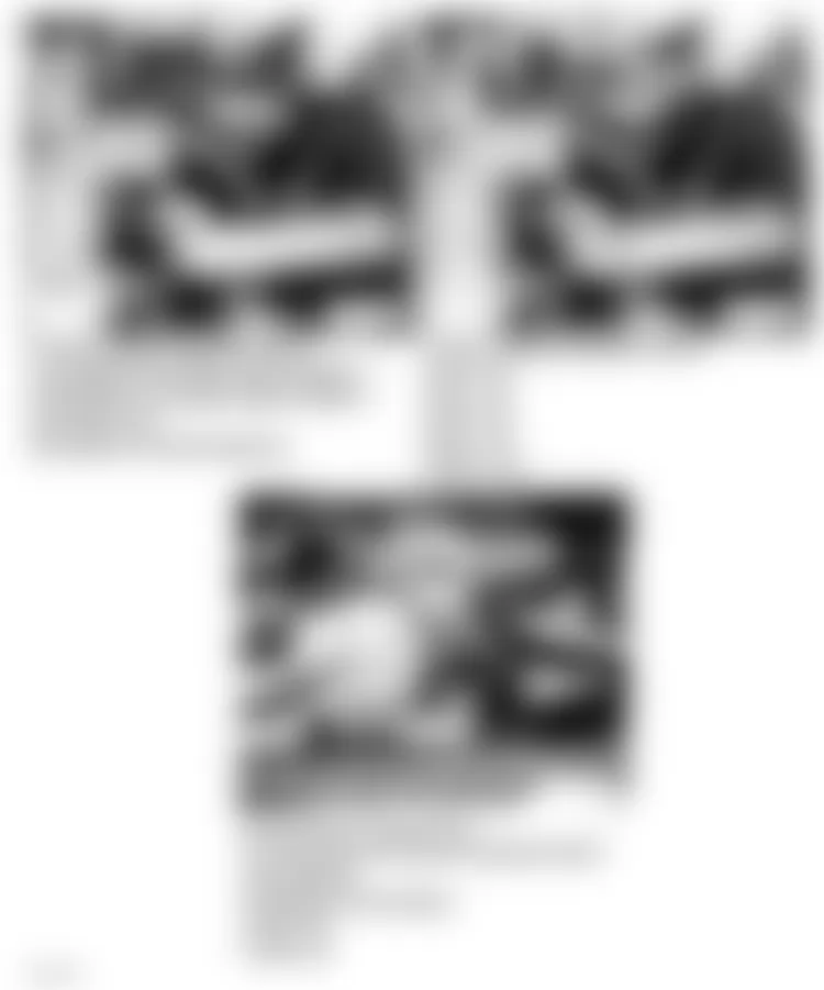
Fig. 7: Land Rover Defender 90 1995 - Component Locations - Component Locations (7 Of 55)

Fig. 8: Land Rover Defender 90 1995 - Component Locations - Component Locations (8 Of 55)

Fig. 9: Land Rover Defender 90 1995 - Component Locations - Component Locations (9 Of 55)

Fig. 10: Land Rover Defender 90 1995 - Component Locations - Component Locations (10 Of 55)
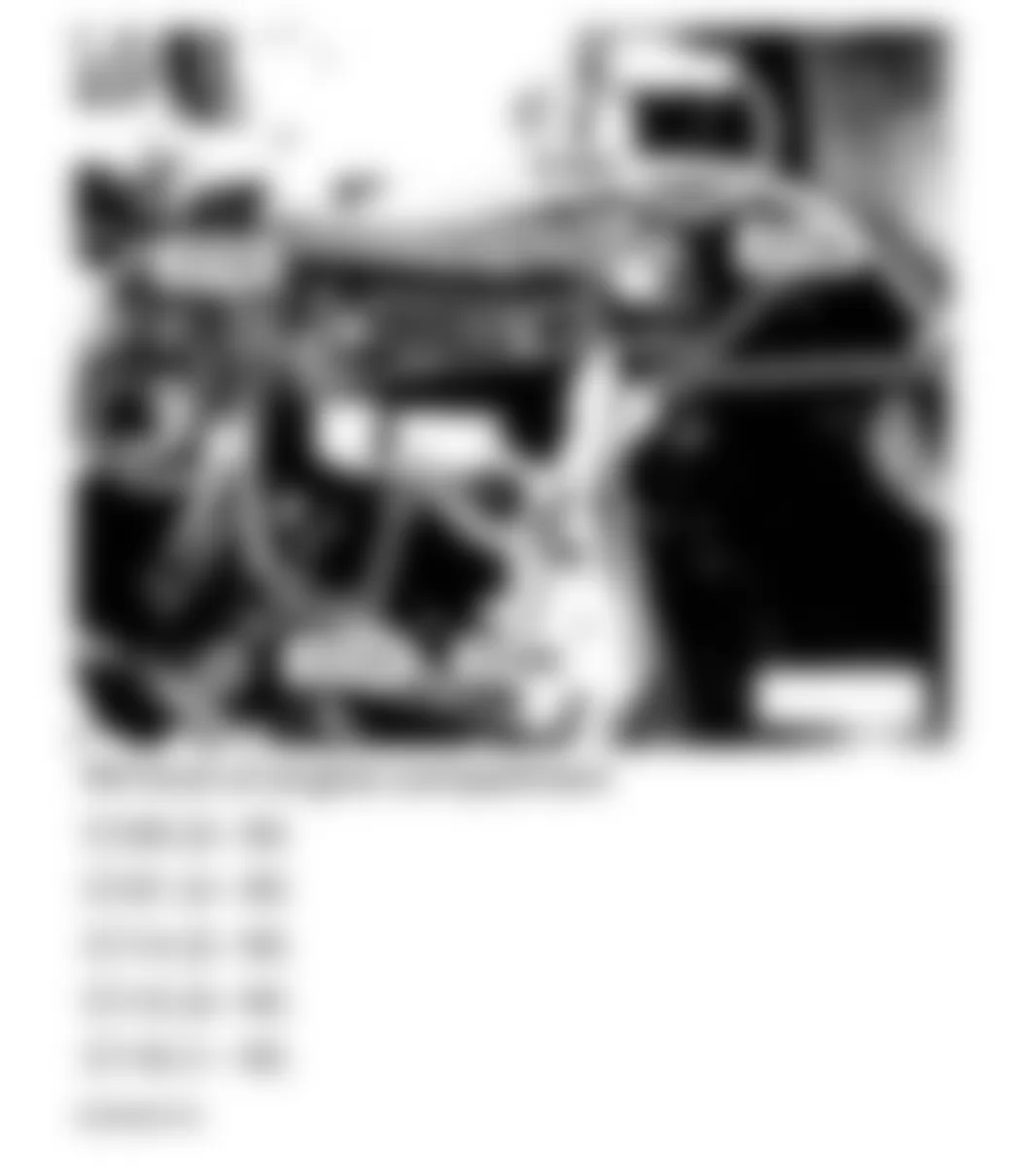
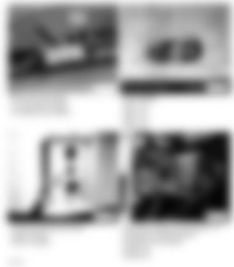
Fig. 11: Land Rover Defender 90 1995 - Component Locations - Component Locations (11 Of 55)
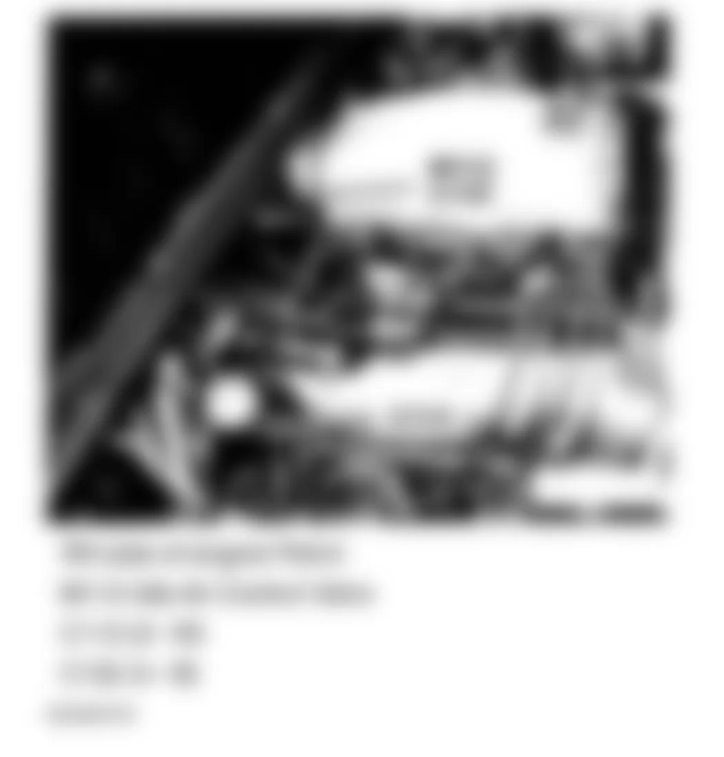
Fig. 12: Land Rover Defender 90 1995 - Component Locations - Component Locations (12 Of 55)
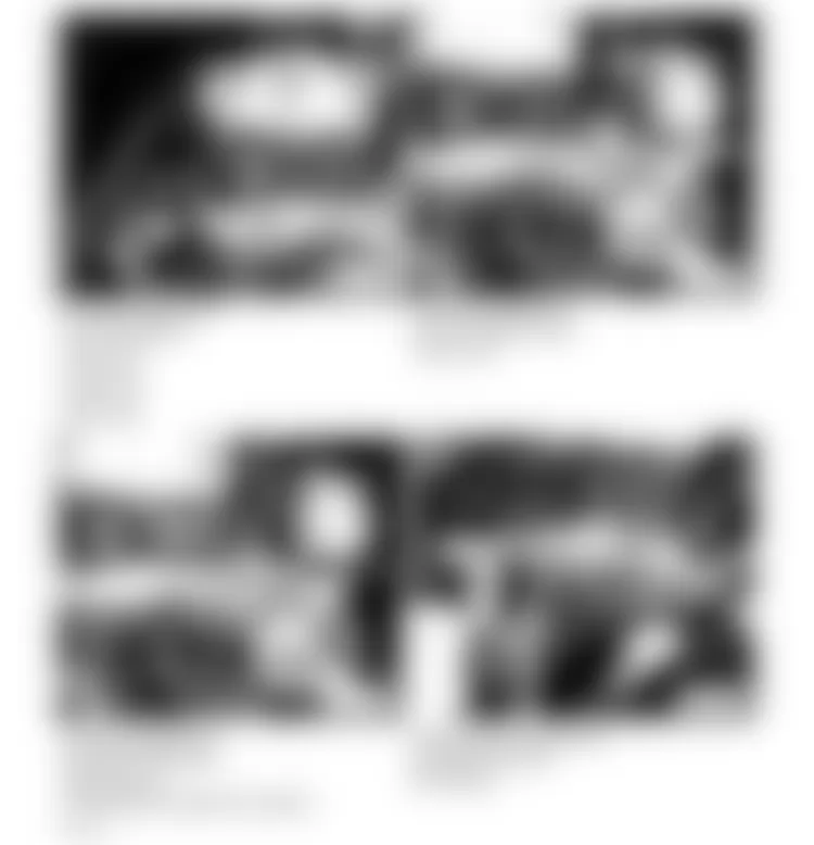
Fig. 13: Land Rover Defender 90 1995 - Component Locations - Component Locations (13 Of 55)
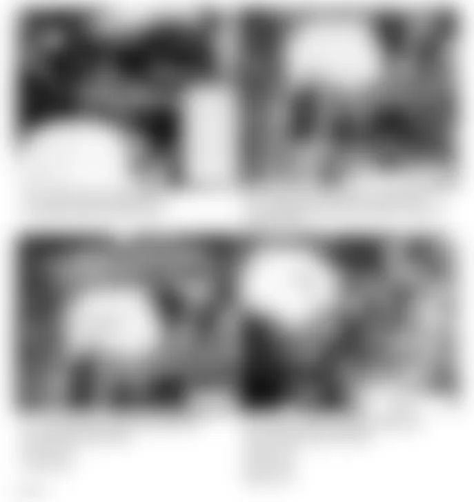
Fig. 14: Land Rover Defender 90 1995 - Component Locations - Component Locations (14 Of 55)
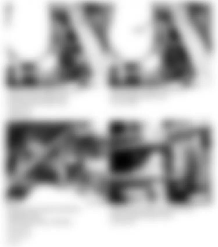
Fig. 15: Land Rover Defender 90 1995 - Component Locations - Component Locations (15 Of 55)
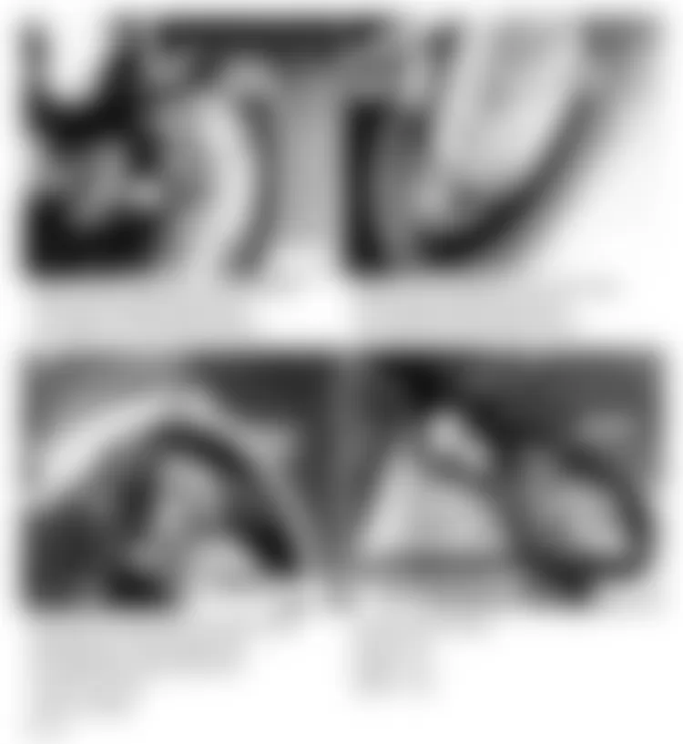
Fig. 16: Land Rover Defender 90 1995 - Component Locations - Component Locations (16 Of 55)
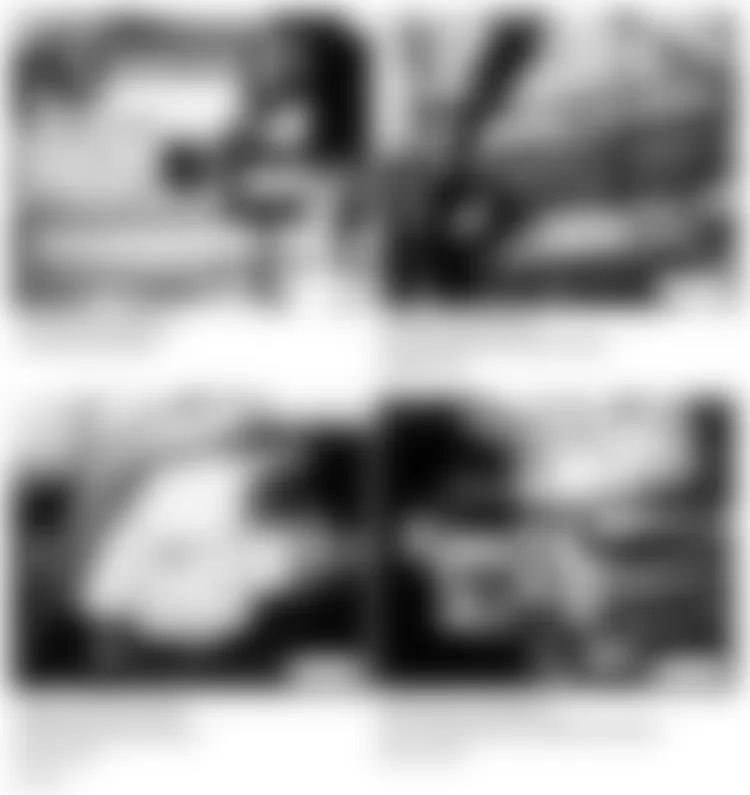
Fig. 17: Land Rover Defender 90 1995 - Component Locations - Component Locations (17 Of 55)

Fig. 18: Land Rover Defender 90 1995 - Component Locations - Component Locations (18 Of 55)

Fig. 19: Land Rover Defender 90 1995 - Component Locations - Component Locations (19 Of 55)
Fig. 20: Land Rover Defender 90 1995 - Component Locations - Component Locations (20 Of 55)
Fig. 21: Land Rover Defender 90 1995 - Component Locations - Component Locations (21 Of 55)
Fig. 22: Land Rover Defender 90 1995 - Component Locations - Component Locations (22 Of 55)
Fig. 23: Land Rover Defender 90 1995 - Component Locations - Component Locations (23 Of 55)
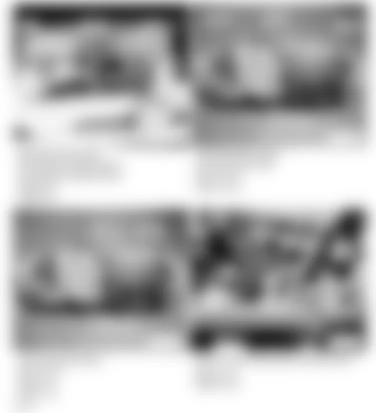
Fig. 24: Land Rover Defender 90 1995 - Component Locations - Component Locations (24 Of 55)
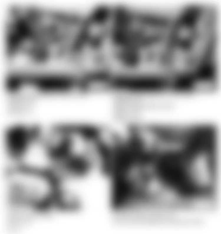
Fig. 25: Land Rover Defender 90 1995 - Component Locations - Component Locations (25 Of 55)
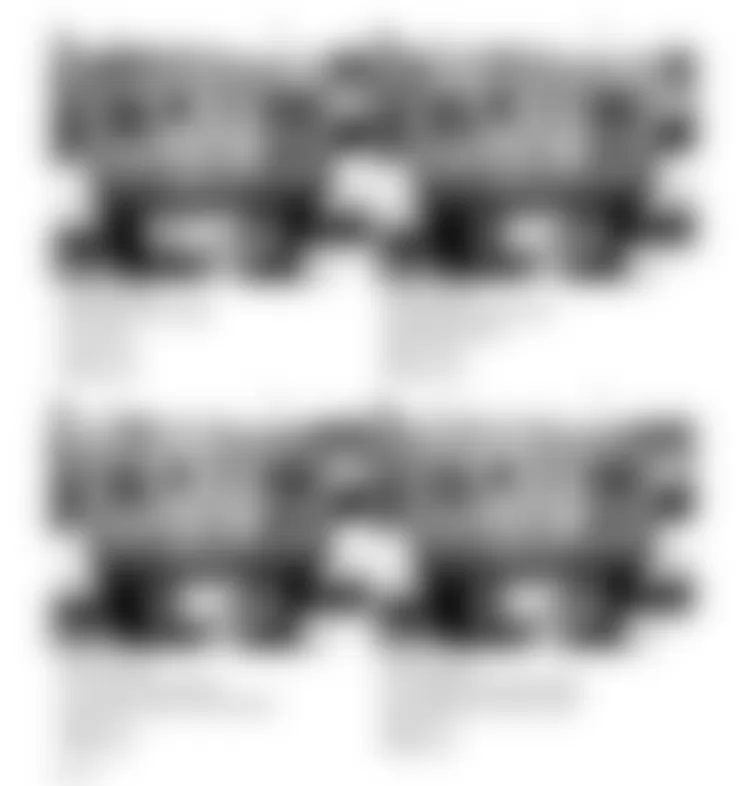
Fig. 26: Land Rover Defender 90 1995 - Component Locations - Component Locations (26 Of 55)
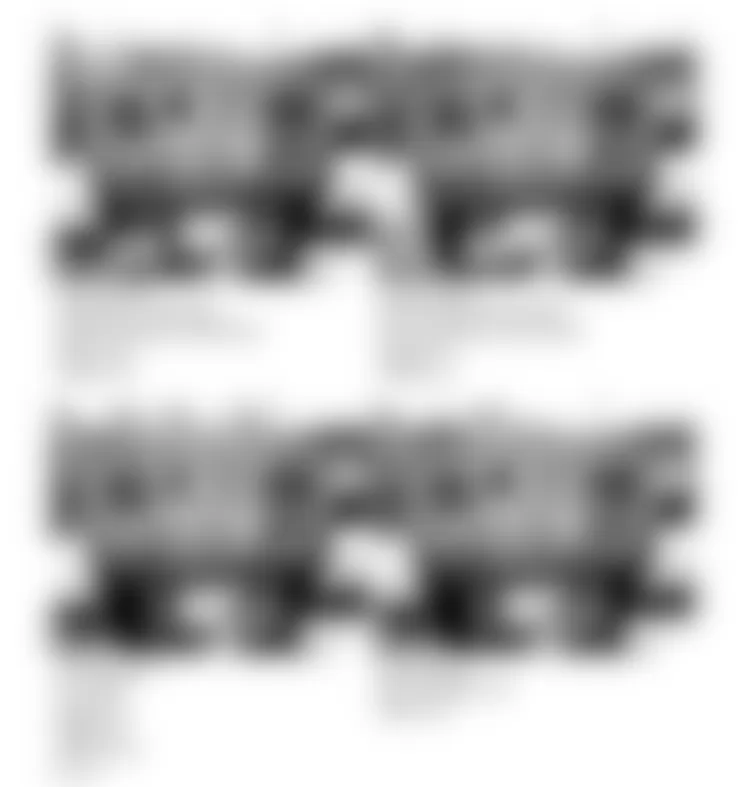
Fig. 27: Land Rover Defender 90 1995 - Component Locations - Component Locations (27 Of 55)
Fig. 28: Land Rover Defender 90 1995 - Component Locations - Component Locations (28 Of 55)

Fig. 29: Land Rover Defender 90 1995 - Component Locations - Component Locations (29 Of 55)
Fig. 30: Land Rover Defender 90 1995 - Component Locations - Component Locations (30 Of 55)
Fig. 31: Land Rover Defender 90 1995 - Component Locations - Component Locations (31 Of 55)
Fig. 32: Land Rover Defender 90 1995 - Component Locations - Component Locations (32 Of 55)
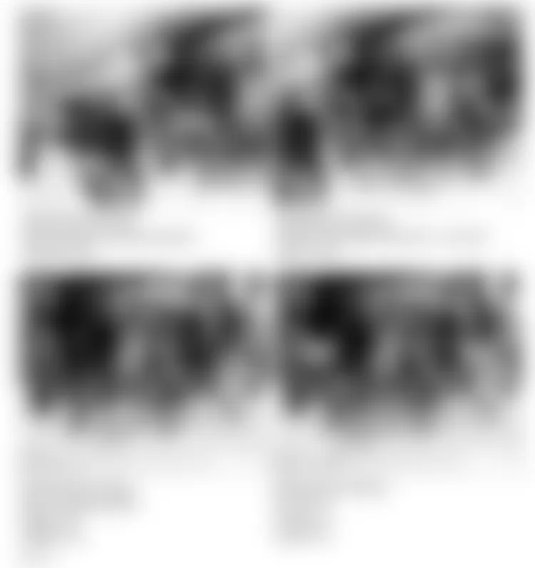
Fig. 33: Land Rover Defender 90 1995 - Component Locations - Component Locations (33 Of 55)

Fig. 34: Land Rover Defender 90 1995 - Component Locations - Component Locations (34 Of 55)
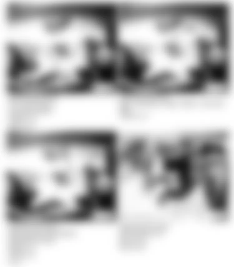
Fig. 35: Land Rover Defender 90 1995 - Component Locations - Component Locations (35 Of 55)
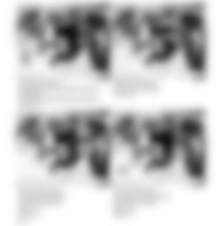
Fig. 36: Land Rover Defender 90 1995 - Component Locations - Component Locations (36 Of 55)

Fig. 37: Land Rover Defender 90 1995 - Component Locations - Component Locations (37 Of 55)
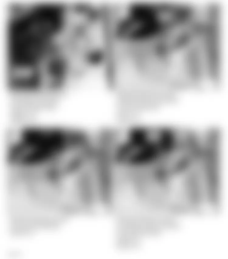
Fig. 38: Land Rover Defender 90 1995 - Component Locations - Component Locations (38 Of 55)

Fig. 39: Land Rover Defender 90 1995 - Component Locations - Component Locations (39 Of 55)
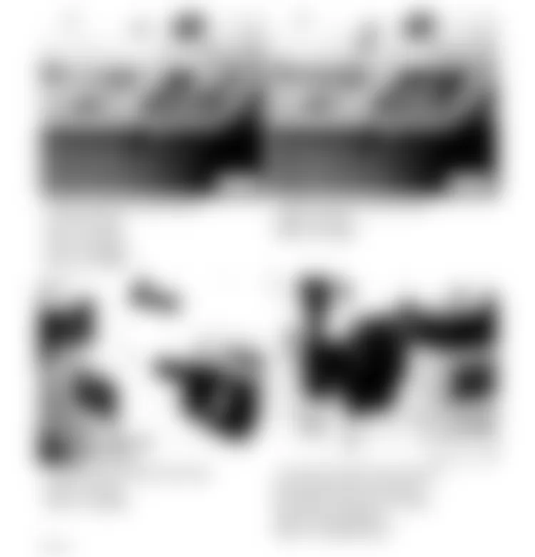
Fig. 40: Land Rover Defender 90 1995 - Component Locations - Component Locations (40 Of 55)
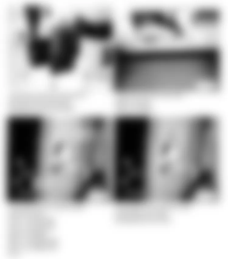
Fig. 41: Land Rover Defender 90 1995 - Component Locations - Component Locations (41 Of 55)
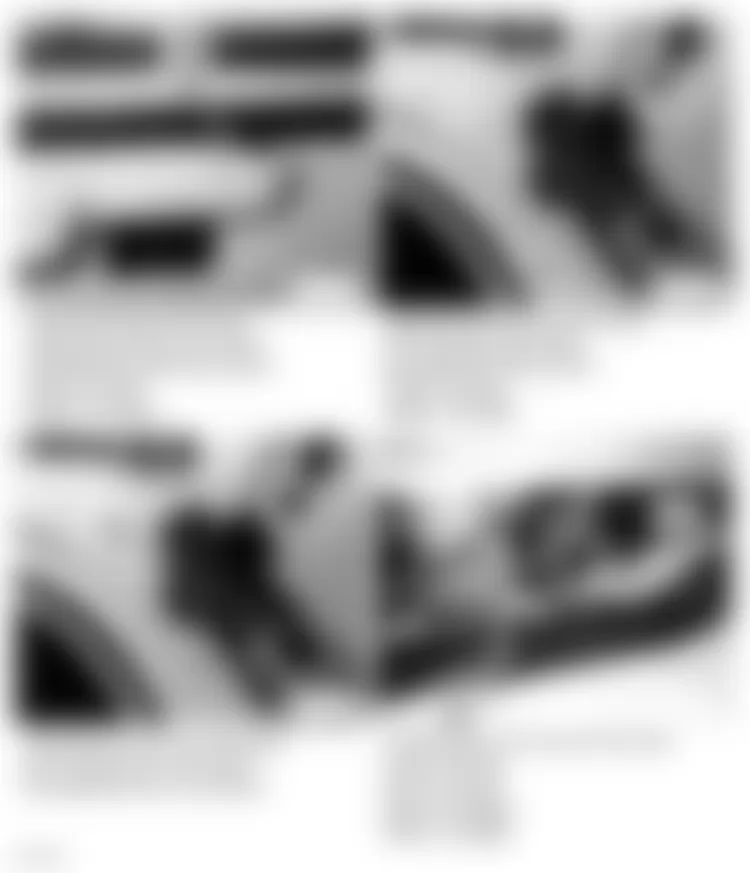
Fig. 42: Land Rover Defender 90 1995 - Component Locations - Component Locations (42 Of 55)
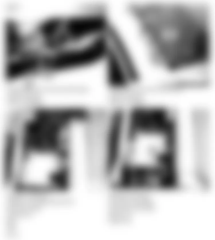
Fig. 43: Land Rover Defender 90 1995 - Component Locations - Component Locations (43 Of 55)
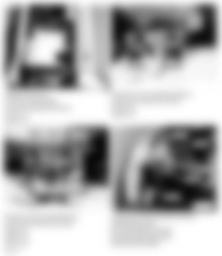
Fig. 44: Land Rover Defender 90 1995 - Component Locations - Component Locations (44 Of 55)
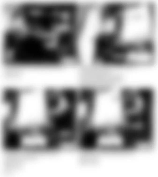
Fig. 45: Land Rover Defender 90 1995 - Component Locations - Component Locations (45 Of 55)

Fig. 46: Land Rover Defender 90 1995 - Component Locations - Component Locations (46 Of 55)
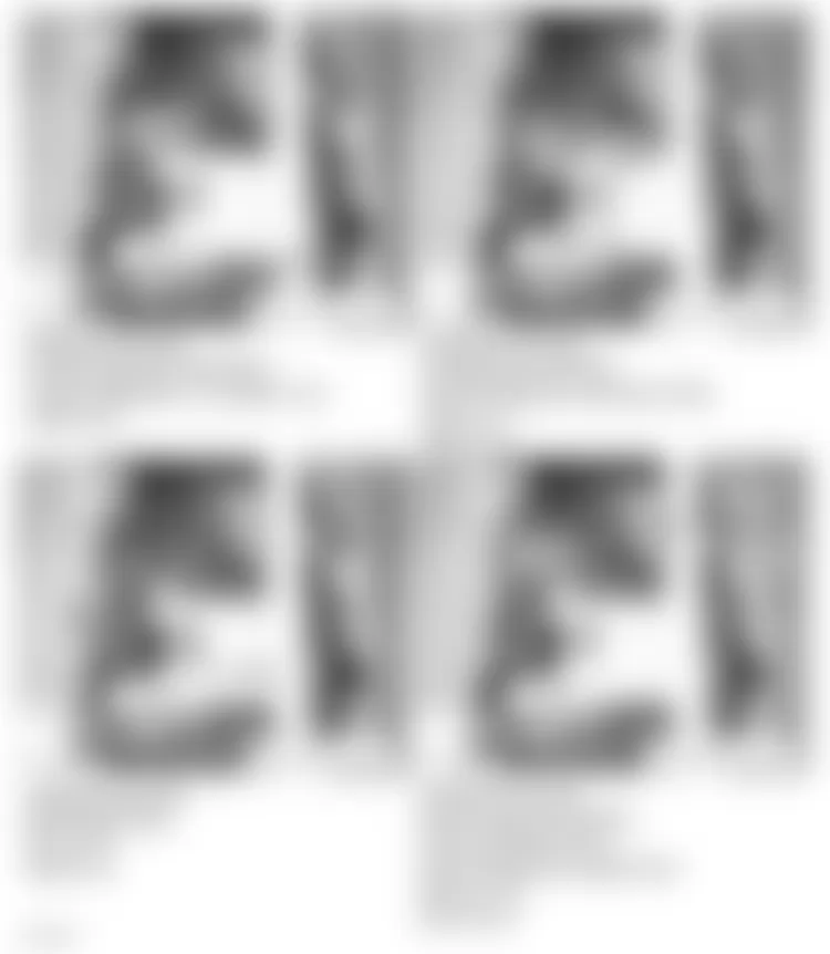
Fig. 47: Land Rover Defender 90 1995 - Component Locations - Component Locations (47 Of 55)
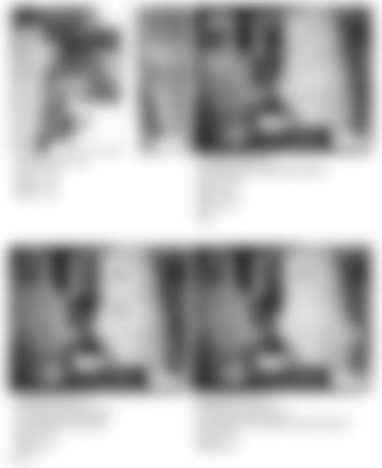
Fig. 48: Land Rover Defender 90 1995 - Component Locations - Component Locations (48 Of 55)
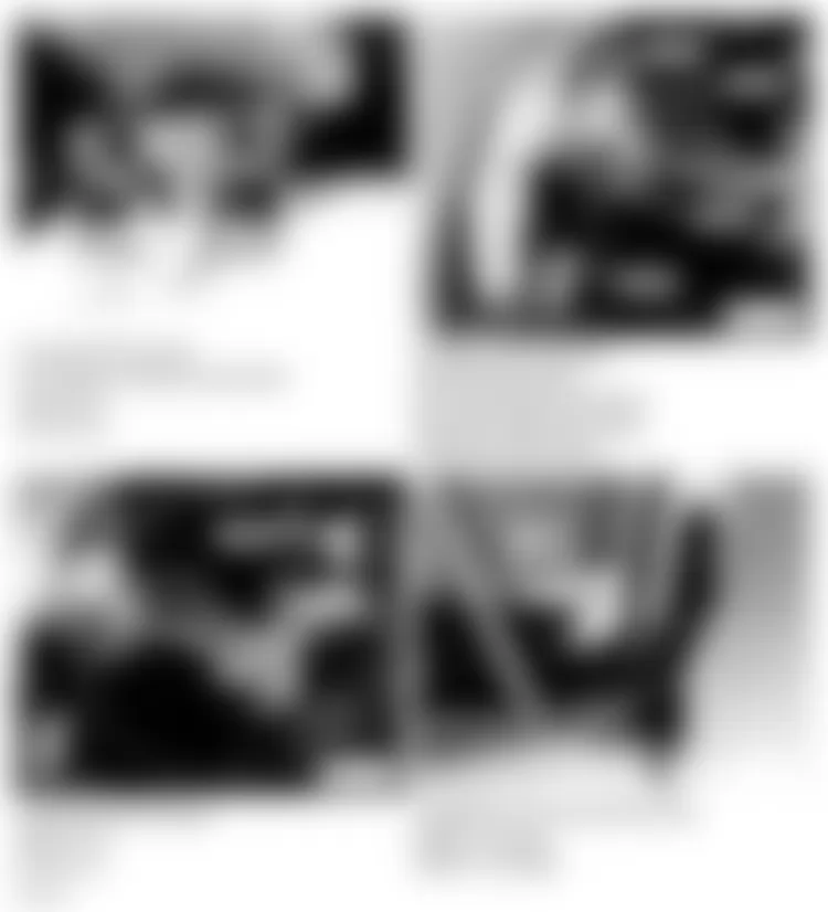
Fig. 49: Land Rover Defender 90 1995 - Component Locations - Component Locations (49 Of 55)
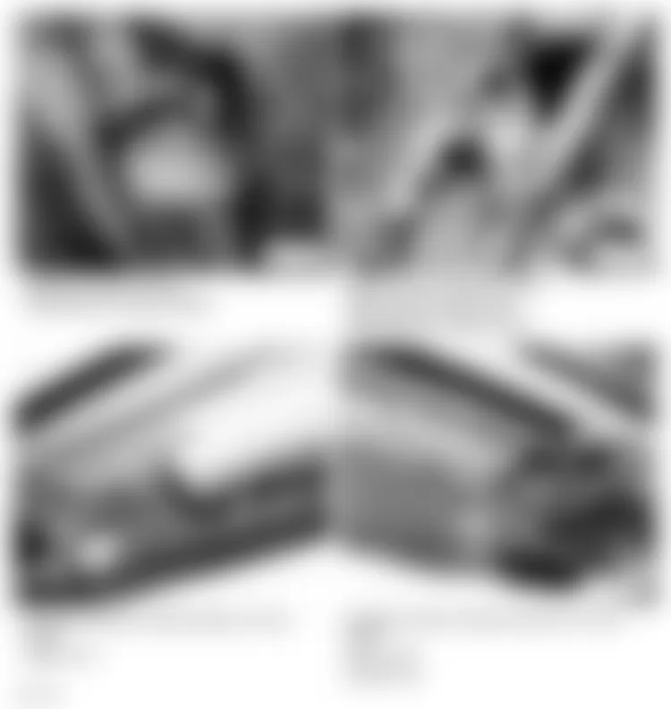
Fig. 50: Land Rover Defender 90 1995 - Component Locations - Component Locations (50 Of 55)
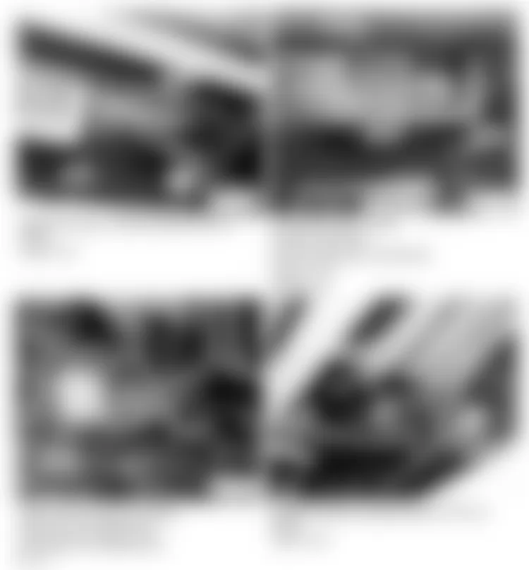
Fig. 51: Land Rover Defender 90 1995 - Component Locations - Component Locations (51 Of 55)
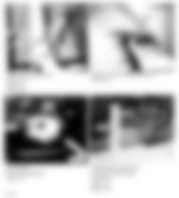
Fig. 52: Land Rover Defender 90 1995 - Component Locations - Component Locations (52 Of 55)
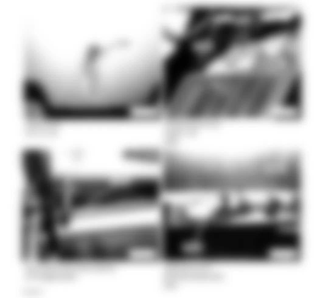
Fig. 53: Land Rover Defender 90 1995 - Component Locations - Component Locations (53 Of 55)
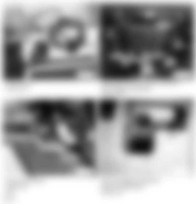
Fig. 54: Land Rover Defender 90 1995 - Component Locations - Component Locations (54 Of 55)
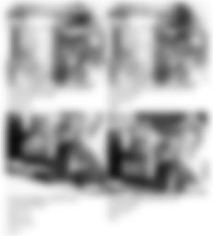
Fig. 55: Land Rover Defender 90 1995 - Component Locations - Component Locations (55 Of 55)
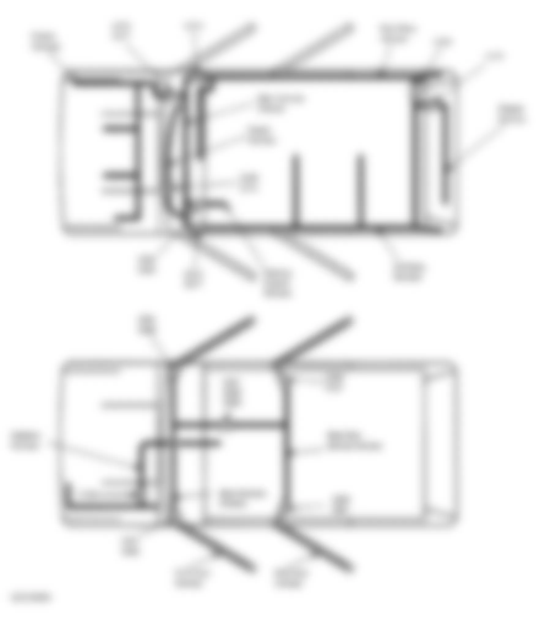
Land Rover Defender 90 1995 - WIRE HARNESS ROUTING
Fig. 56: Land Rover Defender 90 1995 - Component Locations - Wire Harness Routing (1 Of 2)
Fig. 57: Land Rover Defender 90 1995 - Component Locations - Wire Harness Routing (2 Of 2)