MEMORY SYSTEMS
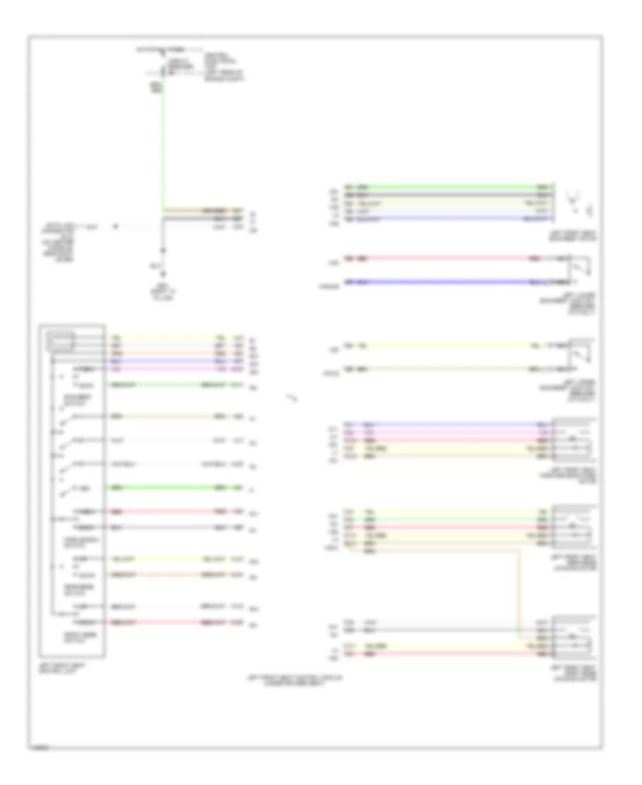
Driver's Memory Seat Wiring Diagram for Volvo V70 GLT 1999
List of elements for Driver's Memory Seat Wiring Diagram for Volvo V70 GLT 1999:
- A10
- A11
- A12
- A13
- A14
- A15
- A16
- Back
- Backrest switch
- C10
- C11
- C12
- C13
- C14
- Central electrical unit (left rear of engine compt)
- Circuit breaker
- Data link connector (dlc) (on center console, near shift lever)
- Down
- Forw
- Forw-backw switch
- Front edge switch
- G901 (right "a" pillar)
- Hot at all times
- Left front seat backrest motor
- Left front seat control module (under driver's seat)
- Left front seat control unit
- Left front seat forward-backward motor
- Left front seat front edge up-down motor
- Left front seat rear edge up-down motor
- Left lower backrest contact breaker (c70 only)
- Left upper backrest contact breaker (c70 only)
- M1+
- M1-
- M2+
- M2-
- M3+
- M3-
- M4+
- M4-
- Mem
- Nca
- R1+
- R1-
- R2+
- R2-
- R3+
- R3-
- R31
- R4+
- R4-
- Rear edge switch
- Red
- Vangle
- Vfold
- Vg1
- Vg2
- Vg3/4
- Vga
- Vgf
- Vr1
- Vr2
- Vr3
- Vr4
 English