MEMORY SYSTEMS
Memory System Wiring Diagrams for Volvo V70 R 1998
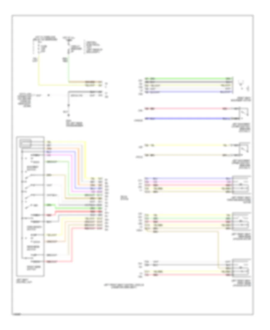
List of elements for Memory System Wiring Diagrams for Volvo V70 R 1998:
- (s70 & v70)
- Back
- Backrest switch
- C10
- C11
- C12
- C13
- C14
- Central electrical unit (left rear of eng compt)
- Circuit breaker
- D10
- D11
- D12
- D13
- D14
- D15
- D16
- Data link connector (on center console, near shift lever)
- Down
- Forw
- Forw-backw switch
- Front edge switch
- Front seat backrest motor
- Fuse c36 15a
- G304 (on left rear crossmember)
- Hot at all times
- Hot w/ overload relay 105 energized
- Left backrest lower contact breaker (c70 only)
- Left backrest upper contact breaker (c70 only)
- Left front seat control module (under driver's seat)
- Left front seat forward-backward motor
- Left front seat front edge up-down motor
- Left front seat rear edge up-down motor
- Left seat control unit
- M1+
- M1-
- M2+
- M2-
- M3+
- M3-
- M4+
- M4-
- Mem
- Nca
- R1+
- R1-
- R2+
- R2-
- R3+
- R3-
- R31
- R4+
- R4-
- Rear edge switch
- Red
- Solid state
- Vangle
- Vfold
- Vg1
- Vg2
- Vg3/4
- Vga
- Vgf
- Vr1
- Vr2
- Vr3
- Vr4
 English