
Mercedes-Benz 300E 4Matic 1992 - G - TESTS W/CODES - 2.6L 1992-93 ENGINE PERFORMANCE Mercedes-Benz 2.6L 6-Cylinder CIS-E Self-Diagnostics
Mercedes-Benz 300E 4Matic 1992 - INTRODUCTION
NOTE: Limited diagnostic information is available for 190E 2.6L.
If no faults were found while performing preliminary inspection, go to RETRIEVING CODES in this article. If no fault codes or only pass codes are present, go to the TESTS W/O CODES article for diagnosis by symptom (i.e., ROUGH IDLE, NO START, etc.).
NOTE: All voltage tests should be performed with a Digital Volt-Ohmmeter (DVOM) with a minimum 10-megohm input impedance, unless specifically stated different in testing procedures.
Mercedes-Benz 300E 4Matic 1992 - SELF-DIAGNOSTIC SYSTEM
NOTE: When diagnosing vehicle, read faults before starting diagnostic work. During some testing procedures, components are disconnected with engine running causing simulated faults. Ensure faults are recorded before starting diagnostic work to ensure only actual faults are diagnosed.
Mercedes-Benz 300E 4Matic 1992 - CIS-E
The CIS-E system is equipped with a self-diagnostic capability for trouble shooting, however, there are 2 methods of retrieving diagnostic information. All vehicles can be tested reading an on/off ratio output as a percentage to identify malfunctioning components or systems. California vehicles can be tested reading stored Diagnostic Trouble Codes (DTC's). Only vehicles built for California have the capability to identify and store a DTC. Federal vehicles can only be diagnosed reading an on/off ratio output as a percentage. On California vehicles, the CIS-E control unit must be switched to output an on/off ratio before diagnosing vehicle using on/off ratio tester.
The CIS-E system can be tested using Pulse Counter (124 589 19 21 00), Contact Box (124 589 00 21 00), 25-Pin Test Cable (124 589 33 63 00), Test Cable (124 589 34 63 00), On/Off Ratio Tester (909 589 00 21 00), DVOM, and on 6-cylinder and 8-cylinder only, Pulse Counter Adapter (140 589 14 63 00).
Mercedes-Benz 300E 4Matic 1992 - PRETEST CONDITIONS
Start and run engine until engine oil temperature is 176?F (80?C). Turn air conditioning off. Ensure shift lever is in Park. Check all fuses and replace as necessary. Verify battery voltage is 11-14 volts.
NOTE: For component locations, see the THEORY/OPERATION - 2.6L article.
Mercedes-Benz 300E 4Matic 1992 - RETRIEVING CODES
NOTE: On CIS-E vehicles, the on/off ratio output is used to diagnose intermittent problems. On CIS-E California vehicles, Diagnostic Trouble Codes (DTC's) are used to diagnose hard failures.
Mercedes-Benz 300E 4Matic 1992 - CIS-E
NOTE: On California vehicles, the CIS-E control unit must be switched to output on/off ratio before diagnosing vehicle using on/off ratio tester. If CIS-E control unit is not switched to output an on/off ratio, on/off ratio output will be wrong resulting in incorrect diagnosis.
Mercedes-Benz 300E 4Matic 1992 - On/Off Ratio Output (CIS-E)
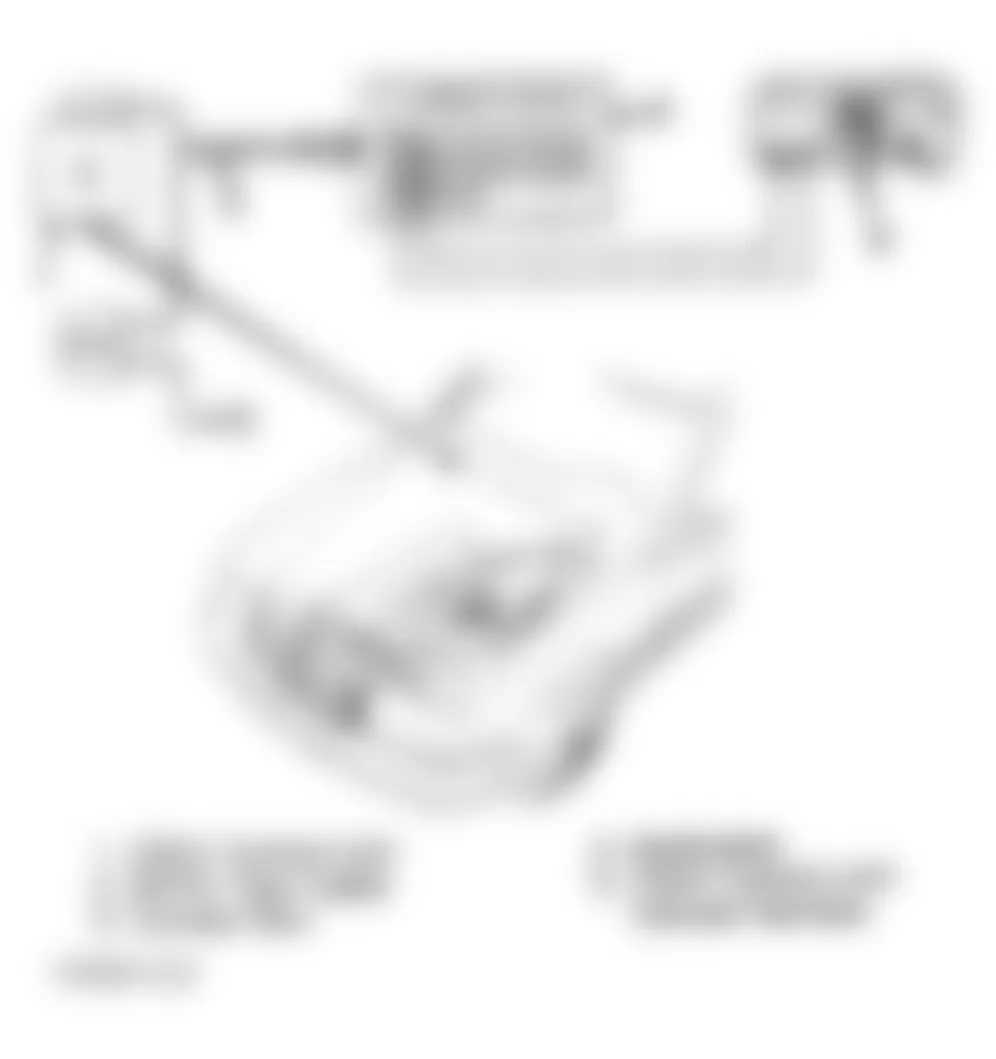
- Turn ignition off. Perform pretest conditions. See PRETEST CONDITIONS . If diagnosing a Federal vehicle, go to step 3). If diagnosing a California vehicle, turn ignition on. Press non-locking switch located on diagnostic connector in right rear corner of engine compartment for 2-4 seconds. See Fig. 1 .
- CIS-E control unit will begin flashing LED light on diagnostic connector. See Fig. 1 . Wait for LED to stop flashing. When LED illuminates constantly, press non-locking switch again for 2-4 seconds. Pressing non-locking switch puts CIS-E control unit into on/off ratio output mode.

Fig. 1: Mercedes-Benz 300E 4Matic 1992 - Component Locations - Connecting On/Off Ratio TesterNOTE: Limited diagnostic information is available for 190E 2.6L. - Connect On/Off Ratio Tester (909 589 00 21 00) to diagnostic connector located on left fender apron. See Fig. 1 . Start engine. Read on/off ratio. Turn ignition off. On 6-cylinder vehicles, see CIS-E (2.6L) under ON/OFF RATIO IDENTIFICATION . On 4-cylinder vehicles, before diagnosing on/off ratio readout, disconnect on/off ratio tester. Connect 25-Pin Test Cable (124 589 33 63 00) between CIS-E control unit and vehicle wiring harness.
- Connect Contact Box (124 589 00 21 00) to 25-pin test cable. See Fig. 2 . See ON/OFF RATIO DIAGNOSIS for testing. If no on/off ratio is output, see NO ON/OFF RATIO OUTPUT under ON/OFF RATIO DIAGNOSIS .
Fig. 2: Mercedes-Benz 300E 4Matic 1992 - Component Locations - Connecting Contact Box
Mercedes-Benz 300E 4Matic 1992 - Diagnostic Trouble Code (DTC CIS-E)
- Turn ignition off. Perform pretest conditions. See PRETEST CONDITIONS . If using a pulse counter to diagnose vehicle, go to step 6). If pulse counter is not available, go to next step.
- If diagnosing California vehicle, turn ignition on. Press non-locking switch located on diagnostic connector in right rear corner of engine compartment for 2-4 seconds. See Fig. 1 .
- CIS-E control unit will begin output of fault codes by flashing LED light on diagnostic connector. See Fig. 1 . If LED only flashes once, this indicates no fault codes are stored. If fault codes are stored, LED will flash indicating stored fault code.
- Press non-locking switch again for 2-4 seconds. If more fault codes are stored, LED on diagnostic connector will display next code. Continue pressing non-locking switch for 2-4 seconds at a time until LED lights steadily indicating end of fault code display.
- Record all fault codes. On 6-cylinder vehicles, refer to CIS-E FAULT CODE IDENTIFICATION to identify fault code. On 4-cylinder vehicles, see CIS-E FAULT CODE IDENTIFICATION to identify fault code and cross-over to an on/off ratio percentage for diagnosis. After crossing-over to an on/off ratio percentage, see ON/OFF RATIO DIAGNOSIS to diagnose vehicle.
- Connect Pulse Counter (124 589 19 21 00) to vehicle battery and diagnostic connector located in right rear corner of engine compartment. See Fig. 3 .
Fig. 3: Mercedes-Benz 300E 4Matic 1992 - Component Locations - Connecting Pulse Counter - U-BATT LED on pulse counter display will illuminate if equipment is properly connected. If U-BATT LED illuminates, go to step 10). If U-BATT LED does not illuminate, check pulse counter fuse. Replace as necessary. If pulse counter fuse is okay, go to next step.
- Using a DVOM, measure voltage between diagnostic connector terminal No. 1 and battery positive terminal. Voltage should be 11-14 volts. If voltage is not 11-14 volts, repair wiring as necessary or replace vehicle battery.
- Using a DVOM, measure voltage between diagnostic connector terminals No. 1 and 3. Voltage should be .7-2.5 volts. If voltage is not .7-2.5 volts, repair wiring as necessary.
- Start engine and idle. Press START button on pulse counter for 2-4 seconds maximum. Pressing push button longer than 2-4 seconds will erase code in memory. Read pulse output on pulse counter. If pulse counter displays "1", no faults are stored. If pulse counter displays a number greater than "1", faults are stored.
- Press start button again for 2-4 seconds. If more fault codes are stored, pulse counter will display next code. Continue pressing start button for 2-4 seconds at a time until pulse counter displays first fault again. Record all fault codes. On 6-cylinder vehicles, see CIS-E FAULT CODE IDENTIFICATION to identify fault code. On 4-cylinder vehicles, see CIS-E FAULT CODE IDENTIFICATION to identify fault code and cross-over to an on/off ratio percentage for diagnosis. After crossing-over to an on/off ratio percentage, see ON/OFF RATIO DIAGNOSIS to diagnose vehicle.

Mercedes-Benz 300E 4Matic 1992 - CIS-E FAULT CODE IDENTIFICATION
Mercedes-Benz 300E 4Matic 1992 CIS-E (2.6L) FAULT CODE IDENTIFICATION
Fault Code Malfunctioning Component/System 1 (1) * 2 Throttle Valve Switch (Full Throttle Contact) 3 Coolant Temperature Sensor 4 Airflow Sensor Potentiometer 5 Oxygen Sensor 6 (2) * 7 TNA (Engine RPM) Signal 8 Altitude Pressure Signal From EZL Ignition Control Unit 9 Current To Electrohydraulic Actuator 10 Throttle Valve Switch (Idle Contact) 11 Air Injection System 12 Absolute Pressure Valves From EZL Ignition Control Unit 13 Intake Air Temperature Signal 14 Road Speed Signal At CIS-E Control Unit 15 (2) * 16 Exhaust Gas Recirculation (EGR) 17 Oxygen Sensor Signal 18 Current To Idle Speed Air Valve 19 (2) * 20 (2) * 21 (2) * 22 Oxygen Sensor Heating Current 23 Short To Positive In Regeneration Switchover Valve Circuit 24 (2) * 25 Short To Positive In Start Valve Circuit 26 Short To Positive In Shift Point Retard Circuit 27 Data Exchange Fault Between CIS-E & EZL Ignition Control Units 28 Loose Contact In Coolant Temp. Sensor Circuit 29 Difference In Coolant Temp. Between CIS-E & EZL Ignition Control Units 30 (2) * 31 Loose Contact In Intake Air Temp. Sensor Circuit 32 (2) * 33 (2) * 34 Faulty Coolant Temp. Sensor Signal From EZL Ign. Control Unit
(1) No faults in system.
(2) Not assigned.
Mercedes-Benz 300E 4Matic 1992 - CLEARING CODES CIS-E
- On Federal vehicles, disconnect vehicle battery. Stored codes are now erased. On California vehicles, disconnecting vehicle battery will not erase codes. Each code stored in CIS-E control unit must be erased individually. Start engine and idle. If using a pulse counter to diagnose vehicle, go to step 3). If pulse counter is not available, go to next step.
- If diagnosing a California vehicle, turn ignition on. Press non-locking switch located on diagnostic connector in right rear corner of engine compartment for 2-4 seconds. When fault is displayed, press non-locking switch for 6-8 seconds. Fault is now cleared. Continue procedure until all stored faults have been erased.
- Press START button on pulse counter for 2-4 seconds maximum. Pulse counter will display fault code. Press start button again for 6-8 seconds. Fault code is erased when pulse counter no longer displays fault code. Repeat procedure for other stored fault codes. When pulse counter displays "1", no faults are stored. Disconnect test equipment.
Mercedes-Benz 300E 4Matic 1992 - ON/OFF RATIO DIAGNOSIS
NOTE: Contact Box (124 589 00 21 00) terminals correspond with CIS-E control unit connector terminals. See Fig. 4 .
Mercedes-Benz 300E 4Matic 1992 - NO ON/OFF RATIO OUTPUT
- Turn ignition on. Connect a voltmeter between contact box terminal No. 2 and battery positive terminal. Voltage should be 11-14 volts. If voltage is within specification, go to next step. If voltage is not within specification, engine ground has an open circuit. Repair as necessary.
- Connect a voltmeter between contact box terminal No. 7 and battery positive terminal. Voltage should be 11-14 volts. If voltage is within specification, go to next step. If voltage is not within specification, CIS-E control unit may be faulty.
- Connect a voltmeter between contact box terminal No. 20 and battery positive terminal. Voltage should be 11-14 volts. If voltage is within specification, go to next step. If voltage is not within specification, battery ground connection is loose or open. Repair as necessary.
- Connect a voltmeter between contact box terminals No. 1 and 2. Voltage should be 11-14 volts. If voltage is within specification, go to next step. If voltage is not within specification, repair open circuit on overvoltage protection relay connector terminal No. 1 (Red wire), terminal No. 2 (Red/Yellow wire) or terminal No. 3 (Black/Red wire).
- Turn ignition off. Disconnect overvoltage protection relay. Connect a voltmeter between contact box terminal No. 2 and overvoltage protection relay connector terminal No. 1 (Red wire). Voltage should be 11-14 volts. If voltage is within specification, go to next step. If voltage is not within specification, repair open circuit in Red wire.
- Turn ignition on. Connect voltmeter between contact box terminal No. 2 and overvoltage protection relay connector terminal No. 3 (Black/Red wire). Voltage should be 11-14 volts. If voltage is within specification, go to next step. If voltage is not within specification, repair open circuit in Black/Red wire.
- Turn ignition off. Connect an ohmmeter between contact box terminal No. 1 and overvoltage protection relay terminal No. 2 (Red/Yellow wire). Resistance should be less than one ohm. If resistance is within specification, go to next step. If voltage is not within specification, repair open circuit in Red/Yellow wire.
- Connect an ohmmeter between contact box terminal No. 2 and overvoltage protection relay connector terminal No. 5 (Brown wire). Resistance should be less than one ohm. If resistance is within specification, go to next step. If resistance is not within specification, repair open circuit in Brown wire.
- Connect a voltmeter between contact box terminals No. 15 and 4. Voltage should be 11-14 volts. If voltage is within specification, go to next step. If voltage is not within specification, overvoltage protection relay may be faulty, fuse may be faulty, or terminal No. 4 wire may be open. Repair as necessary.
- Turn ignition off. Connect an ohmmeter between contact box terminals No. 15 and 4. Resistance should be less than one ohm. If resistance is within specification, go to next step. If resistance is not within specification, repair open circuit.
- Connect Test Cable (102 545 04 63 00) to electrohydraulic actuator. Electrohydraulic actuator is located on fuel distributor assembly. Connect DVOM to test cable. Turn ignition on. Measure current at electrohydraulic actuator under different operating conditions. See the ELECTROHYDRAULIC ACTUATOR CURRENT SPECIFICATIONS table below.
Mercedes-Benz 300E 4Matic 1992 ELECTROHYDRAULIC ACTUATOR CURRENT SPECIFICATIONS
Condition Milliamps Ignition On, Engine Off 20 40 Seconds After Engine Start W/O2 Sensor Disconnected (1) -1 - 1 Engine Idling At Operating Temperature -3 - 3 Engine Warm-Up Enrichment 8-14 Acceleration Enrichment (Blipping Throttle) More Than 15 Engine At Partial Load Fluctuating (1) Engine coolant temperature 68?F (20?C) or less. - If electrohydraulic actuator current is within specification, go to next step. If electrohydraulic actuator current is not within specification, possible failures are electrohydraulic actuator, wiring, CIS-E control unit or CIS-E resistance trimming plug. Repair or replace components as necessary.
- Turn ignition off. Disconnect CIS-E control unit from test harness. Disconnect test cable from electrohydraulic actuator. Connect ohmmeter between contact box terminals No. 10 and 12. Resistance should be 18.5-20.5 ohms. If resistance is within specification, go to next step. If resistance is not within specification, replace electrohydraulic actuator or repair wiring as necessary.
- Disconnect electrical connector from electrohydraulic actuator. Connect an ohmmeter between electrohydraulic actuator terminals. Resistance should be 18.5-20.5 ohms. If resistance is within specification, go to next step. If resistance is not within specification, replace electrohydraulic actuator.
- Connect an ohmmeter between contact box terminal No. 10 and electrohydraulic actuator connector terminal No. 2 (Brown/Black wire). Resistance should be less than one ohm. If resistance is less than one ohm, go to next step. If resistance is more than one ohm, repair open circuit.
- Connect an ohmmeter between contact box terminal No. 12 and electrohydraulic actuator connector terminal No. 1 (Black wire). Resistance should be less than one ohm. If resistance is within specification, go to next step. If resistance is not within specification, repair open circuit.
- Connect an ohmmeter between contact box terminals No. 7 and 22. Resistance should be less than one ohm. If resistance is within specification, test is complete. If resistance is not within specification, jumper in wiring harness has an open circuit. Repair as necessary.
NOTE: Before performing ON/OFF RATIO ZERO PERCENT, if an on/off ratio of 10-90 percent is indicated with ignition on and engine off, do not perform steps 1), 2) or 3).
Mercedes-Benz 300E 4Matic 1992 - ON/OFF RATIO ZERO PERCENT
- Turn ignition off. Disconnect CIS-E control unit from test cable. Connect an ohmmeter between contact box terminal No. 23 and diagnostic connector terminal No. 3. Diagnostic connector is located on left fender apron. Resistance should be less than one ohm. If resistance is within specification, go to next step. If resistance is not within specification, repair open circuit between CIS-E control unit connector and diagnostic connector. Diagnostic connector is located on left fender apron.
- With ignition off, connect a voltmeter between vehicle battery negative terminal and diagnostic connector terminal No. 6. Diagnostic connector is located on left fender apron. Voltage should be 11-14 volts. If voltage is within specification, go to next step. If voltage is not within specification, replace fuse No. 9 as necessary or repair open circuit.
- With ignition off, connect a voltmeter between diagnostic connector terminal No. 2 and vehicle battery positive terminal. Diagnostic connector is located on left fender apron. Voltage should be 11-14 volts. If voltage is within specification, go to next step. If voltage is not within specification, repair open ground circuit.
- Connect CIS-E control unit to test harness. Connect on/off ratio tester to diagnostic connector located in right rear corner of engine compartment. Diagnostic connector is located on left fender apron. Start engine and idle. With engine at operating temperature, Lambda control on/off ratio should be 40-60 percent. If on/off ratio is within specification, test is complete. If on/off ratio is not within specification, ensure engine control system is functioning properly (i.e. air intake system, coolant temperature sensor, oxygen sensor, etc.). If engine control system is functioning properly, adjust CO as necessary.
Mercedes-Benz 300E 4Matic 1992 - ON/OFF RATIO 10 PERCENT
- With ignition on and on/off ratio tester connected to diagnostic connector located on left fender apron, open microswitch on throttle body without opening throttle valve. If on/off ratio tester output changes to 70 percent, go to next step. If on/off ratio tester output is 20 percent, go to ON/OFF RATIO 20 PERCENT. If on/off ratio tester output is 40 percent, see ON/OFF RATIO 40 PERCENT.
- Turn ignition off. Disconnect CIS-E control unit from test harness. Disconnect EZL control unit connector numbered 1-4. Connect an ohmmeter between contact box terminals No. 2 and 13. Resistance should be less than one ohm. Depress accelerator pedal. Resistance reading should change to infinity. If resistance readings are within specification, go to next step. If resistance readings are not within specification, check throttle valve switch connector for correct polarity, faulty idle speed contact, or wiring failure. Repair as necessary.
- Disconnect throttle valve switch connector. Connect an ohmmeter between throttle valve switch connector terminal No. 1 (Brown/Yellow wire) and terminal No. 2 (Brown wire). Resistance should be less than one ohm. Depress accelerator pedal. Resistance reading should change to infinity. If resistance readings are not within specification, adjust or replace throttle valve switch or repair faulty wiring as necessary.
- Connect an ohmmeter between contact box terminal No. 13 and throttle valve switch connector (harness side) terminal No. 1 (Brown/Yellow wire). Resistance should be less than one ohm. If resistance is within specification, go to next step. If resistance is not within specification, repair open circuit in Brown/Yellow wire.
- Connect an ohmmeter between contact box terminal No. 2 and throttle valve switch connector (harness side) terminal No. 2 (Brown wire). Resistance should be less than one ohm. If resistance is less than one ohm, test is complete. If resistance is more than one ohm, repair open circuit in Brown wire.
Mercedes-Benz 300E 4Matic 1992 - ON/OFF RATIO 20 PERCENT
- Turn ignition off. Disconnect CIS-E control unit from test harness. Connect an ohmmeter between contact box terminals No. 2 and 5. Resistance reading should be infinity. Depress accelerator pedal to full load position. Resistance reading should change to less than one ohm. If resistance readings are within specifications, to next step. If resistance readings are not within specification, check throttle valve switch connector for correct polarity, faulty full load contact, or wiring failure. Repair as necessary.
- Disconnect throttle valve switch connector. Connect an ohmmeter between throttle valve switch connector (component side) terminal No. 2 (Brown wire) and terminal No. 3 (Green wire). Resistance reading should be infinity. Depress accelerator to full load position. Resistance reading should change to less than one ohm. If resistance readings are within specification, go to next step. If resistance readings are not within specification, adjust or replace throttle valve switch.
- Connect an ohmmeter between contact box terminal No. 5 and throttle valve switch connector (harness side) terminal No. 3 (Gray/Yellow wire). Resistance should be less than one ohm. If resistance is within specification, go to next step. If resistance is not within specification, repair open circuit in Gray/Yellow wire.
- Connect an ohmmeter between contact box terminal No. 2 and throttle valve switch connector (harness side) terminal No. 2 (Brown wire). Resistance should be less than one ohm. If resistance is within specification, test is complete. If resistance is not within specification, repair open circuit in Brown wire.
Mercedes-Benz 300E 4Matic 1992 - ON/OFF RATIO 30 PERCENT
- With engine idling at operating temperature and CIS-E control unit connected to test harness, connect a voltmeter between contact box terminals No. 7 and 21. Voltage should be .29-.35 volts with coolant temperature at 176?F (80?C). For other voltage specifications at different temperatures, refer to the COOLANT TEMPERATURE SENSOR SPECIFICATIONS table. If voltage is within specification, go to next step.
- Disconnect coolant temperature sensor connector. Connect an ohmmeter between 2 coolant temperature sensor terminals diagonally. Measure remaining 2 coolant temperature sensor terminals diagonally. Resistance reading will vary with coolant temperature sensor temperature. See COOLANT TEMPERATURE SENSOR SPECIFICATIONS table. If resistance is within specification, go to next step. If resistance is not within specification, replace coolant temperature sensor.
Mercedes-Benz 300E 4Matic 1992 COOLANT TEMPERATURE SENSOR SPECIFICATIONS
Temperature ?F (?C) Ohms Volts -4 (-20) 15,700 3.24-3.94 14 (-10) 9200 2.84-3.47 32 (0) 5900 2.39-2.93 50 (10) 3700 1.94-2.37 68 (20) 2500 1.51-1.84 86 (30) 1700 1.16-1.42 104 (40) 1180 .88-1.08 122 (50) 840 .66-.80 140 (60) 600 .50-.61 158 (70) 435 .38-.46 176 (80) 325 .29-.35 194 (90) 247 .22-.26 - Connect an ohmmeter between negative battery terminal and coolant temperature sensor connector terminal No. 4 (Brown/White wire). Resistance should be less than one ohm. If resistance is within specification, go to next step. If resistance is not within specification, repair open circuit in Brown/White wire.
- Connect an ohmmeter between contact box terminal No. 21 and coolant temperature sensor connector terminal No. 2 (Green/Red wire). Resistance should be less than one ohm. If resistance is within specification, test is complete. If resistance is not within specification, repair open circuit in Green/Red wire.
Mercedes-Benz 300E 4Matic 1992 - ON/OFF RATIO 40 PERCENT
- With engine idling at operating temperature and CIS-E control unit connected to test harness, connect a voltmeter between contact box terminals No. 7 and 17. Voltage should be .55-.95 volts. If voltage is within specification, go to next step. If voltage is not within specification, replace faulty airflow sensor potentiometer.
- Connect a voltmeter between contact box terminals No. 7 and 18. Voltage should be 4.6-5.1 volts. If voltage is within specification, go to next step. If voltage is not within specification, CIS-E control unit may be faulty.
- Turn ignition off. Connect an ohmmeter between contact box terminal No. 7 and airflow sensor connector terminal No. 1 (Brown/White wire). Resistance should be less than one ohm. If resistance is within specification, go to next step. If resistance is not within specification, repair open circuit in Brown/White wire.
- Connect an ohmmeter between contact box terminal No. 18 and airflow sensor connector terminal No. 3 (Blue/Green wire). Resistance should be less than one ohm. If resistance is within specification, go to next step. If resistance is not within specification, repair open circuit in Blue/Green wire.
- Connect an ohmmeter between contact box terminal No. 17 and airflow sensor connector terminal No. 2 (Blue/Black wire). Resistance should be less than one ohm. If resistance is within specification, go to next step. If resistance is not within specification, repair open circuit in Blue/Black wire.
- Connect an ohmmeter between airflow sensor terminals No. 1 (Brown/White wire connects to terminal) and 3 (Blue/Green wire connects to terminal). Resistance should be 3.6-4.4 ohms. If resistance is within specification, go to next step. If resistance is not within specification, replace faulty airflow sensor.
- Connect an ohmmeter between airflow sensor terminals No. 1 (Brown/White wire connects to terminal) and 2 (Blue/Black wire connects to terminal). Slowly deflect airflow sensor plate by hand. Resistance value should increase continuously up to 2/3 of deflection, then drop off. If resistance increases continuously up to 2/3 of deflection, then drop off, test is complete. If resistance does not increase continuously up to 2/3 of deflection, then drop off, replace airflow sensor.
Mercedes-Benz 300E 4Matic 1992 - ON/OFF RATIO 50 PERCENT
- With engine idling at operating temperature and CIS-E control unit connected to test harness, connect a voltmeter between contact box terminals No. 7 and 8. Voltage should fluctuate .1-.9 volts. If voltage is within specification, go to next step. If voltage is not within specification, replace faulty oxygen sensor, repair faulty wiring, or replace faulty CIS-E resistance trimming plug.
- With engine idling at operating temperature, disconnect one wire oxygen sensor connector (Black wire). Ground oxygen sensor connector (harness side) to simulate a lean condition. Connect a voltmeter between contact box terminal No. 7 and one wire oxygen sensor connector (Black wire) sensor side. Voltage should be greater than 450 millivolts. If voltage is within specification, go to next step. If voltage is not within specification, replace oxygen sensor.
- Turn ignition off. Disconnect CIS-E control unit from test harness. Connect an ohmmeter between contact box terminal No. 7 and 8. Ohmmeter should read infinity. If ohmmeter reading is correct, go to next step. If ohmmeter reading is not correct, repair faulty wiring.
- Connect an ohmmeter between contact box terminal No. 8 and one wire oxygen sensor connector (Black wire) harness side. Resistance should be less than one ohm. If resistance is within specification, test is complete. If resistance is not within specification, repair open circuit.
Mercedes-Benz 300E 4Matic 1992 - ON/OFF RATIO 60 PERCENT
- Turn ignition on. During measurement, move vehicle approximately 3.5 feet. Connect a voltmeter between contact box terminals No. 2 and 6. Move vehicle at least 3.5 feet. Voltage should fluctuate 0-12 volts. If voltage is within specification, go to next step. If voltage is not within specification, repair faulty wiring or replace defective hall-effect speed sensor.
- Connect an ohmmeter between contact box terminal No. 6 and hall-effect speed sensor connector White wire. Resistance should be less than one ohm. If resistance is within specification, go to next step. If resistance is not within specification, repair open circuit in White wire.
- With on/off ratio tester connected to diagnostic connector located on left fender apron, drive vehicle in 3rd gear accelerating to 2000 RPM for approximately 6 seconds. On/off ratio readout should fluctuate after easing off accelerator pedal. If on/off ratio readout fluctuates after easing off accelerator pedal, test is complete. If on/off ratio reads 60 percent, replace CIS-E control unit.
Mercedes-Benz 300E 4Matic 1992 - ON/OFF RATIO 70 PERCENT
- With engine idling at operating temperature and CIS-E control unit connected to test harness, connect a voltmeter between contact box terminals No. 2 and 25. Voltage should be 6-12 volts. If voltage is within specification, go to next step. If voltage is not within specification, repair faulty wiring or replace faulty EZL ignition control unit.
- Turn ignition off. Connect an ohmmeter between contact box terminal No. 25 and diagnostic connector terminal No. 1 (Green/Yellow wire). Diagnostic connector is located on left fender apron. Resistance should be less than one ohm. If resistance is within specification, go to next step. If resistance is not within specification, repair open circuit in Green/Yellow wire.
- Disconnect EZL ignition control unit 4-pin connector with 2 wires (Brown wire and Green/Yellow wire). Connect an ohmmeter between EZL ignition control unit 4-pin connector Green/Yellow wire and diagnostic connector terminal No. 1 (Green/Yellow wire). Diagnostic connector is located on left fender apron. Resistance should be less than one ohm. If resistance is within specification, test is complete. If resistance is not within specification, repair open circuit in Green/Yellow wire.
Mercedes-Benz 300E 4Matic 1992 - ON/OFF RATIO 80 PERCENT
- Turn ignition on. With CIS-E control unit connected to test harness, connect a voltmeter between contact box terminals No. 7 and 18. Voltage should be 4.6-5.1 volts. If voltage is within specification, go to next step. If voltage is not within specification, repair faulty wiring or faulty altitude correction sensor.
- Connect a voltmeter between contact box terminals No. 7 and 11. For voltage specification, refer to the ALTITUDE CORRECTION SENSOR SPECIFICATIONS table. If voltage is within specification, go to next step. If voltage is not within specification, replace altitude correction sensor.
Mercedes-Benz 300E 4Matic 1992 ALTITUDE CORRECTION SENSOR SPECIFICATIONS
Altitude (Feet) Air Pressure: psi Volts 0 14.6 3-5 1000 13 2-4 2000 11.5 1-2 - Turn ignition off. Disconnect altitude correction sensor connector. Connect an ohmmeter between contact box terminal No. 11 and altitude correction sensor terminal No. 3 (Brown/White wire). Resistance should be less than one ohm. If resistance is within specification, go to next step. If resistance is not within specification, repair open circuit in Brown/White wire.
- Connect an ohmmeter between contact box terminal No. 18 and altitude correction sensor terminal No. 2 (Blue/Green wire). Resistance should be less than one ohm. If resistance is within specification, go to next step. If resistance is not within specification, repair open circuit in Blue/Green wire.
- Connect an ohmmeter between contact box terminal No. 11 and altitude correction sensor terminal No. 1 (Blue/Red wire). Resistance should be less than one ohm. If resistance is within specification, go to next step. If resistance is not within specification, repair open circuit in Blue/Red wire.
Mercedes-Benz 300E 4Matic 1992 - ON/OFF RATIO 90 PERCENT
Not assigned.
Mercedes-Benz 300E 4Matic 1992 - ON/OFF RATIO 100 PERCENT
An on/off ratio of 100 percent indicates idle speed is too high. See ON/OFF RATIO ZERO PERCENT and ON/OFF RATIO 50 PERCENT to diagnose an on/off ratio of 100 percent.
Mercedes-Benz 300E 4Matic 1992 - ON/OFF RATIO IDENTIFICATION CIS-E (2.6L) On/Off Ratio Zero Percent
Check possible failures in order given:
- No voltage or ground at diagnostic connector located on left fender apron.
- Wiring between diagnostic connector and CIS-E control unit may have an open circuit.
- On/off ratio tester may be faulty.
- Air/fuel mixture may be too rich.
Mercedes-Benz 300E 4Matic 1992 - On/Off Ratio 10 Percent
Check possible failures in order given:
- Airflow sensor potentiometer may have incorrect polarity or is faulty (idle RPM may be fast).
- Throttle valve switch connector may have incorrect polarity or full load contact is shorted.
Mercedes-Benz 300E 4Matic 1992 - On/Off Ratio 20 Percent
Full load contact may have incorrect polarity or is faulty. On/off ratio of 20 percent is output when throttle valve switch is operated.
Mercedes-Benz 300E 4Matic 1992 - On/Off Ratio 30 Percent
Check possible failures in order given:
- Short circuit may be present between CIS-E control unit and coolant temperature sensor.
- Coolant temperature sensor may be faulty.
Mercedes-Benz 300E 4Matic 1992 - On/Off Ratio 40 Percent
Check possible failures in order given:
- Open or short circuit may be present between CIS-E control unit and airflow sensor potentiometer.
- Airflow sensor potentiometer may be faulty (idle RPM may be fast).
Mercedes-Benz 300E 4Matic 1992 - On/Off Ratio 50 Percent
Check possible failures in order given:
- Oxygen sensor may not be operational or faulty.
- Oxygen sensor wiring may have an open circuit.
Mercedes-Benz 300E 4Matic 1992 - On/Off Ratio 60 Percent
No road speed signal (speedometer) at CIS-E control unit. Road speed signal is only checked by CIS-E control unit when vehicle is moving. If an incorrect speed signal is detected, on/off ratio of 60 percent is output. If no speed signal is present, vehicle will jerk when moving with throttle valve closed.
Mercedes-Benz 300E 4Matic 1992 - On/Off Ratio 70 Percent
Check possible failures in order given:
- No engine speed (TNA) signal.
- Open circuit to CIS-E control unit.
Mercedes-Benz 300E 4Matic 1992 - On/Off Ratio 80 Percent
Check possible failures in order given:
- Open or short circuit to ground for intake air temperature sensor.
- Intake air temperature sensor may be faulty.
- Malfunction in data interchange between CIS-E control unit and EZL ignition control unit.
Mercedes-Benz 300E 4Matic 1992 - On/Off Ratio 85 Percent
On/off ratio readout of 85 percent means CIS-E control unit has the capability to output a pulse readout.
Mercedes-Benz 300E 4Matic 1992 - On/Off Ratio 90 Percent
No current to electrohydraulic actuator.
Mercedes-Benz 300E 4Matic 1992 - On/Off Ratio 95 Percent
On/off ratio readout of 95 percents means CIS-E control unit is in deceleration fuel shutoff mode.
Mercedes-Benz 300E 4Matic 1992 - On/Off Ratio 100 Percent
Check possible failures in order given:
- No voltage or ground at CIS-E control unit or CIS-E control unit is faulty.
- Air/fuel mixture may be too lean.
- Oxygen sensor may be faulty or shorted to ground.
- Overvoltage protection relay fuse may be faulty.
- On/off ratio tester may be faulty.
Mercedes-Benz 300E 4Matic 1992 - On/Off Ratio Fluctuates
All monitored signals are functioning properly.