Mercedes-Benz 300SE 1991 - G - TESTS W/CODES - GASOLINE 1991 ENGINE PERFORMANCE Self-Diagnostics - Gasoline
Mercedes-Benz 300SE 1991 - INTRODUCTION
If no faults were found while performing basic test procedures in the BASIC TESTING article, proceed with ENTERING SELF-DIAGNOSTICS. If no fault codes or only pass codes are present, proceed to the H - TEST W/O CODES article in this section for diagnosis by symptom (i.e. ROUGH IDLE, NO START, etc.).
NOTE: All voltage tests should be performed with a Digital Volt-Ohmmeter (DVOM) with a minimum 10-megohm input impedance, unless specifically stated different in testing procedures.
Mercedes-Benz 300SE 1991 - SELF-DIAGNOSTIC SYSTEM HARD FAILURES
Hard failures cause CHECK ENGINE light to illuminate and remain on until the malfunction is repaired. If CHECK ENGINE light comes on and remains on or flashes during vehicle operation, cause of malfunction must be determined using diagnostic (code) charts. If a sensor fails, CIS-E control unit will use a substitute value in its calculations to continue engine operation. In this condition, vehicle is functional, but loss of good driveability will most likely be encountered.
NOTE: The Engine Systems Control Unit is referred to throughout this article as MAS.
Mercedes-Benz 300SE 1991 - INTERMITTENT FAILURES
Intermittent failures may cause CHECK ENGINE light to flicker, or illuminate and then go out after the intermittent fault goes away. The corresponding trouble code, however, will be retained in CIS-E control unit memory and MAS memory. If related fault does not reoccur within a certain time frame, related trouble code will be erased from CIS-E control unit memory. Intermittent failures may be caused by sensor, connector or wiring related problems. See INTERMITTENTS in the H - TEST W/O CODES article in this section.
Mercedes-Benz 300SE 1991 - ON-BOARD DIAGNOSTICS USING MAS UNIT MEMORY
- When engine is running and a fault occurs, any fault codes or malfunctions are also stored in MAS unit memory as well as CIS-E control unit memory.
- On 190E Series and 300 Series except 300SE and 300SEL, MAS unit codes can be read using impulse counter connected directly to diagnostic connector pin sockets No. 1 and No. 14.
- On 300SE and 300SEL, MAS unit codes can ONLY be read using socket box tester connected between MAS unit and MAS unit connector socket. Connect Black impulse counter lead to diagnostic connector pin socket No. 4. Connect Yellow lead to socket box tester pin socket No. 14.
Mercedes-Benz 300SE 1991 - ENTERING SELF-DIAGNOSTICS FLASH CODE METHOD (CALIFORNIA)
An on-board test connection with push button and light emitting diodes is located on left, rear engine compartment firewall. See Fig. 1 . To enter self-diagnostics, turn ignition on and press diagnostic connector push button No. 2, for 2-4 seconds. See Fig. 1 and Fig. 2 . Impulse readout will commence flashing code sequence. Codes may also be retrieved through use of an impulse counter.

Mercedes-Benz 300SE 1991 - IMPULSE COUNT READOUT
- To retrieve codes, connect Impulse Counter (124 589 19 21 00) to diagnostic connector, or by connect Multimeter and Socket Box Tester (124 589 00 21 00) by test cables to CIS-E control unit or to MAS unit (if equipped). See Fig. 2 . Connect appropriate tester as shown in appropriate illustration. See Fig. 3 -5. On models equipped with V8 engine, use only multimeter, socket box tester and CIS-E control unit diagram.
- Connect impulse counter leads to diagnostic connector pins No. 1 and No. 3. Connect red wire to battery voltage. See Fig. 4 and Fig. 5 . Using multimeter, connect leads to socket box tester pin sockets No. 1 and No. 2. Remove CIS-E control unit connector. Connect socket box tester connectors to CIS-E control unit and to CIS-E control unit harness connector as shown in appropriate illustration. See Fig. 3 -5.


Mercedes-Benz 300SE 1991 - RETRIEVING CODES FLASH CODE METHOD (CALIFORNIA)
Enter self-diagnostics. See ENTERING SELF-DIAGNOSTICS . Malfunction code will be indicated by number of flashes emitted from LED on diagnostic connector. Upon completion of each flash code impulse readout, LED will remain on. Press push button No. 2 again for 2-4 seconds. If another malfunction exists, it will be indicated at this time by new flash code numbers. If no other malfunction is detected, CIS-E control unit switches over to on-off ratio readout. See TESTING WITH ON-OFF RATIO TESTER .
Mercedes-Benz 300SE 1991 - IMPULSE COUNTER READOUT
Enter self-diagnostics. See ENTERING SELF-DIAGNOSTICS . Turn ignition on. Ensure drive selector is in Park or Neutral position. If using impulse tester, press START button on impulse tester for 2-4 seconds maximum. If using multimeter, press diagnostic connector pin No. 2 push button for 2-4 seconds maximum. Impulse counter or multimeter will now indicate code(s) stored in memory by digital readout or by needle impulses. Pressing push button longer than 2-4 seconds will erase code in memory.
Mercedes-Benz 300SE 1991 - CLEARING CODES
Disconnecting battery WILL NOT erase codes. Each code stored in CIS-E control unit and MAS unit memory must be erased individually. After malfunction code is displayed, wait 2 seconds then press START button for at least 6-10 seconds. LED will blink once, or impulse readout will display "=1", indicating code is erased. Continue this sequence until all codes are erased and only "=1" is displayed. Disconnect test equipment.
Mercedes-Benz 300SE 1991 - TESTING PREPARATION
To test CIS-E control unit system after malfunction codes are retrieved, use Multimeter and Socket Box Tester (124 589 00 21 00) connected by test cables to CIS-E control unit. See Fig. 3 -5. Connect multimeter leads to socket box tester pin sockets No. 1 and No. 3. Remove CIS-E control unit connector. Connect socket box tester connectors to CIS-E control unit and to CIS-E control unit harness connector according to diagram. See Fig. 3 -5.
Mercedes-Benz 300SE 1991 - TESTING WITH ON-OFF RATIO TESTER
NOTE: Perform On-Off Ratio Test and record results. Proceed to appropriate TEST STEP as indicated in TROUBLE SHOOTING charts. See appropriate TEST STEP CHARTS and perform indicated circuit tests to repair vehicle:
- 6-cylinder models, see: TEST STEP CHARTS - 6-CYLINDER
- V8 models, see: TEST STEP CHARTS - V8
Mercedes-Benz 300SE 1991 - ON-OFF RATIO TEST
- Connect On-Off Ratio Tester (Bosch KDJE-P 600) to diagnostic socket (Circuit TD, located on left side of engine compartment). See Fig. 4 . Turn ignition on. Perform On-Off Ratio tests. Record results of "%" readout shown on On-Off Ratio Tester. See TROUBLE SHOOTING - IGNITION ON, ENGINE OFF TABLE.
- Start engine and allow to idle. Perform and record results of percentage readout shown on on-off ratio tester. See TROUBLE SHOOTING - ENGINE AT IDLE table.
- After recording % readouts from both tests and note test steps to be performed, refer to appropriate test step and correct the malfunction. See TEST STEP CHARTS. - the following list.
- 6-cylinder models, see: TEST STEP CHARTS - 6-CYLINDER
- V8 models, see: TEST STEP CHARTS - V8
Mercedes-Benz 300SE 1991 - LOCATING CIS-E & MAS CONTROL UNITS
Mercedes-Benz 300SE 1991 CIS-E AND MAS CONTROL UNIT LOCATIONS
Model Location 190E Series Behind battery, Right, rear of engine bay. 300 Series (Exc. 300SE & 300SEL) Behind battery, Right, rear of engine bay. 300SE & 300SEL Under right, front passenger seat 420 & 560 Series Under right, front passenger seat
Mercedes-Benz 300SE 1991 - SUMMARY
If no hard fault codes are present, proceed to the appropriate H - TEST W/O CODES article in this section for diagnosis by symptom (i.e. ROUGH IDLE, NO START, etc.) or by intermittent diagnosis procedures.
Mercedes-Benz 300SE 1991 - TROUBLE SHOOTING
Mercedes-Benz 300SE 1991 TROUBLE SHOOTING - IGNITION ON, ENGINE OFF
On-Off Ratio % Readout Malfunction Test Step 0 Not Used Not Used 10 Throttle Valve Switch Idle Contacts Open 10.0-10.3 20 Throttle Valve Switch Full Load Contacts Closed 5.0-5.3 30 Coolant Temp. Not Between 158?-212?F (70?-100?C) 6.0-6.3 40 Airflow Sensor Plate Deflected 7.0-7.6 50 Input Signals In Order N/A 60 Speed Signal Recognized 11.0-11.2 70 Starter Signal Circuit No. 50 Recognized 20.0 80 Drive Position Selected N/A 90 Current at EHA Unlikely 4.0-4.4 100 Not Used N/A
Mercedes-Benz 300SE 1991 COOLANT TEMPERATURE SENSOR SPECIFICATIONS
?F (?C) Ohms Volts at Socket -4 -(20) 15,700 3.24-3.94 14 (-10) 9200 2.84-3.47 32 (0) 5900 2.39-2.93 50 (10) 3700 1.94-2.37 68 (20) 2500 1.51-1.84 86 (30) 1700 1.16-1.42 104 (40) 1180 0.88-1.08 122 (50) 840 0.66-0.80 140 (60) 600 0.50-0.61 158 (70) 435 0.38-0.46 176 (80) 325 0.29-0.35 194 (90) 247 0.22-0.26
Mercedes-Benz 300SE 1991 MALFUNCTION DIAGNOSTIC CODES (IMPULSE READOUT OF CIS-E CONTROL UNIT)
Code No. Malfunction Test Step Possible Cause 1 No System Malfunction N/A N/A 2 TV Switch Contacts-Full Load 5.0-5.3 Short in ckt 31 3 Coolant Temp. Sensor 6.0-6.3 Short in ckt 15, 30, &/or 31 4 Airflow Sensor Position Indicator 7.0-7.6 Short in ckt 15, 30, &/or 31 5 Oxygen Sensor 14.0-14.3 N/A 6 Not Used Not Used Not Used 7 NA Signal (RPM) 8.0-8.1 Open ckt 8 Altitude Pressure Signal Vacuum Line or EZL Control Unit 9 Electro-Hydraulic Actuator (EHA) 4.0-4.4 Short in ckt 15, 30, &/or 31 10 TV Switch-Idle Contacts 10.0-10.3 Short in ckt 31 11 Air Injection System 16.0-16.4 Pneumatic 12 Absolute Pressure Values From EZL Control Unit Vacuum line or EZL Control Unit 13 Intake Air Temp. Sensor 13.0-13.3 Short in ckt 15, 30, &/or 31 14 Speed Signal Sensor 11.0-11.2 Short in ckt 15, 30, &/or 31 15 Not Used Not Used Not Used 16 EGR 21.0-22.2 Electric/Pneumatic 17 O2 Sensor Wire Shorted to B+ or Ground 14.0-14.3 Short in ckt 15, 30, &/or 31 18 Idle Speed Air Valve 18.0-18.3 Short in ckt 15, 30, &/or 31 19 Not Used Not Used Not Used 20 Not Used Not Used Not Used 21 Not Used Not Used Not Used 22 O2 Sensor Heating Current 14.4-14.8 N/A 23 Purge Switchover Valve Shorted to B+ 19.1-19.4 Short in ckt 15, &/or 30 24 Not Used Not Used Not Used 25 Start Valve Shorted to B+ 17.0-17.2 Short in ckt 15, &/or 30 26 Shift Point Delay Shorted to B+ N/A N/A 27 Data Exchange Between CIS-E Control Unit & EZL Control Unit Interrupted 12.0 Check if control units are compatible 28 Coolant Temp. Sensor Intermittent N/A Repair wiring or unit 29 CIS-E & EZL control units read different temperature 6.0-6.3 Check CTS ckt to EZL 30 Not Used Not Used Not Used 31 Intake Air Temp. Intermittent N/A Repair wiring or replace unit 32 Not Used Not Used Not Used 33 Not Used Not Used Not Used 34 EZL control unit reading unlikely temp. N/A Short in ckt 15, 30, &/or 31, or CTS ckt shorted to EZL
Mercedes-Benz 300SE 1991 TROUBLE SHOOTING - ENGINE AT IDLE
On-Off Ratio % Readout Malfunction Test Step 0 Open in ground ckt at diagnostic connector pin socket No. 2. Open ckt in wire to diagnostic connector pin socket No. 3 or No. 6, or on-off ratio tester is defective. Mixture adjustment possibly too rich. (1) Repair as necessary 10 Airflow sensor position indicator polarity reversed or defective 7.0-7.6 10 Connector terminals of throttle valve switch reversed (idle and full load contacts) 5.0-5.3 10 Idle contacts open with microswitch closed 10.0-10.3 20 Full load contacts defective or throttle valve switch polarity reversed 5.0-5.3 20 20% is displayed only when microswitch activated Repair as necessary 30 Short or open ckt between CIS-E control unit and coolant temp. sensor 6.0-6.3 30 Defective coolant temperature sensor, or excessive deviation in temperature values in comparison with EZL ignition control unit Repair as necessary 40 Open or short in airflow sensor position indicator wiring, or defective airflow sensor position indicator 7.0-7.6 50 O2 sensor not operational or defective, or open in ckt 14.0-14.3 60 Unlikely speed signal at CIS-E control unit 11.0-11.2 70 Unlikely TNA-signal (RPM) at CIS-E control unit 8.0-8.1 80 Interrupted data exchange between EZL ignition control unit & CIS-E control unit 12.0 90 Unlikely current reading at EHA 4.0-4.4 95 Deceleration fuel shut-off valve in operation Repair as necessary 100 No voltage or ground at CIS-E control unit, or CIS-E control unit defective, or On-off ratio tester defective 1.0-3.0 100 Lambda adjustment too lean. O2 sensor defective (short to ground). 14.0-14.7 Needle Oscillates. No malfunctions of signals monitored N/A
(1) Check fuse No. 9 to be defective.
Mercedes-Benz 300SE 1991 - TEST STEP CHARTS TEST STEP CHARTS - 6-CYLINDER
Mercedes-Benz 300SE 1991 CONNECTOR ABBREVIATIONS DEFINITIONS - 6-CYL.
Connector Definition A 1p8 Electronic Speedometer Connector B 2 Airflow Sensor Position Indicator B 11/2 Coolant Temperature Sensor B 17/2 Air Temperature Sensor G 3/2x1 O2 Sensor Heater Connector To MAS G 3/2x2 O2 Sensor Connector to CIS-E K 1/1 Overvoltage Protection Relay N 1/2 Ignition Control Unit (EZL) N 3 CIS-E Control Unit N 16 Engine Systems Control Unit (MAS) S 29/2 Throttle Valve Switch S 29/2x1 Throttle Valve SwitchConnector W 10 Ground Connection W 11 Ground Connection X 11 Diagnostic Socket X 53/5 Hall Effect Sensor Connector Y 1 Electrohydraulic Actuator (EHA) Y 6 Idle Speed Air Valve Y 8 Start Valve Y 27 EGR Switchover Valve Y 32 Air Injection Pump Switchover Valve Y 33 Electromagnetic Air Injection Pump Clutch Y 58/1 Purge Switchover Valve 50 Starter Circuit
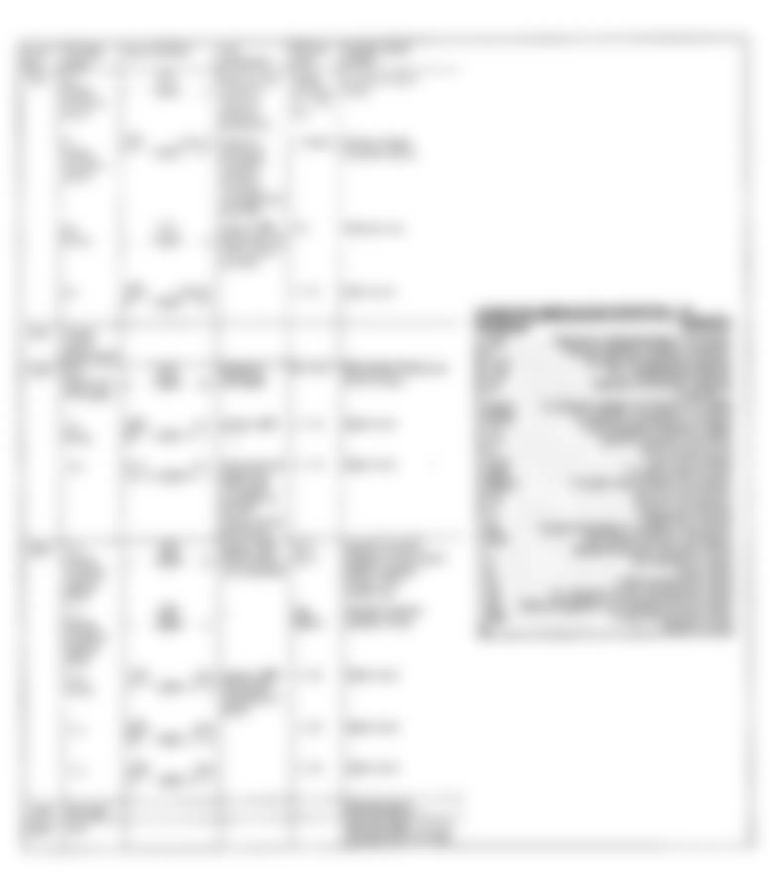
Fig. 6: Mercedes-Benz 300SE 1991 - Component Locations - 6 - CYLINDER TEST STEP CHARTS (1 of 9)
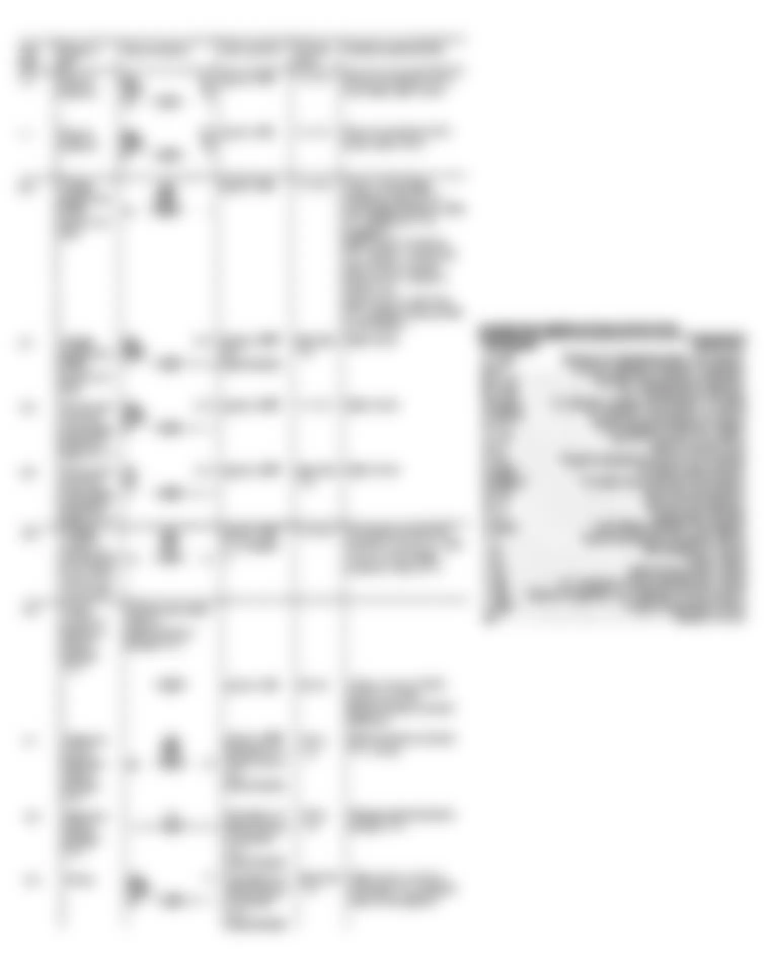
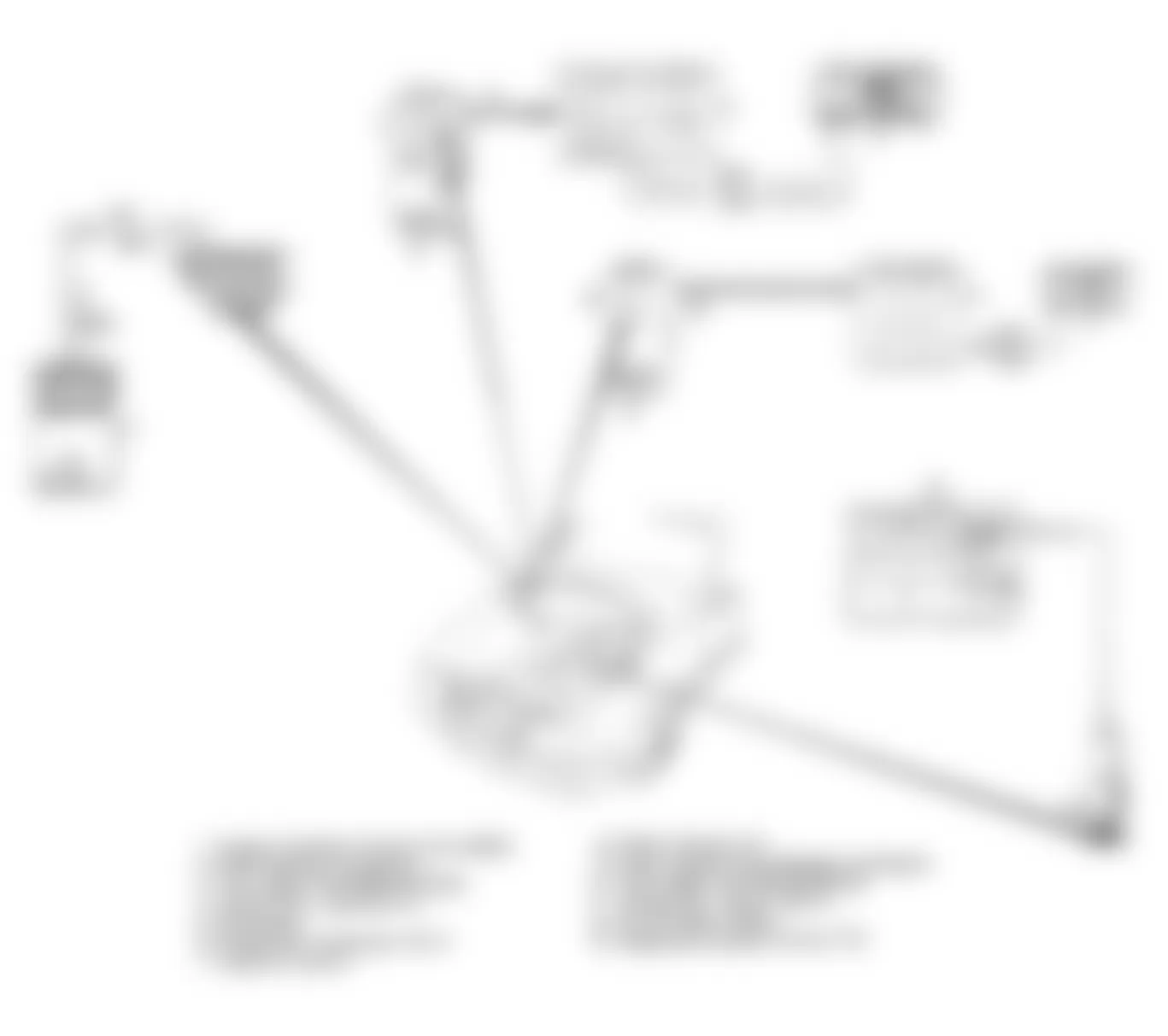
Fig. 7: Mercedes-Benz 300SE 1991 - Component Locations - 6 - Cylinder Test Step Charts (2 of 9)
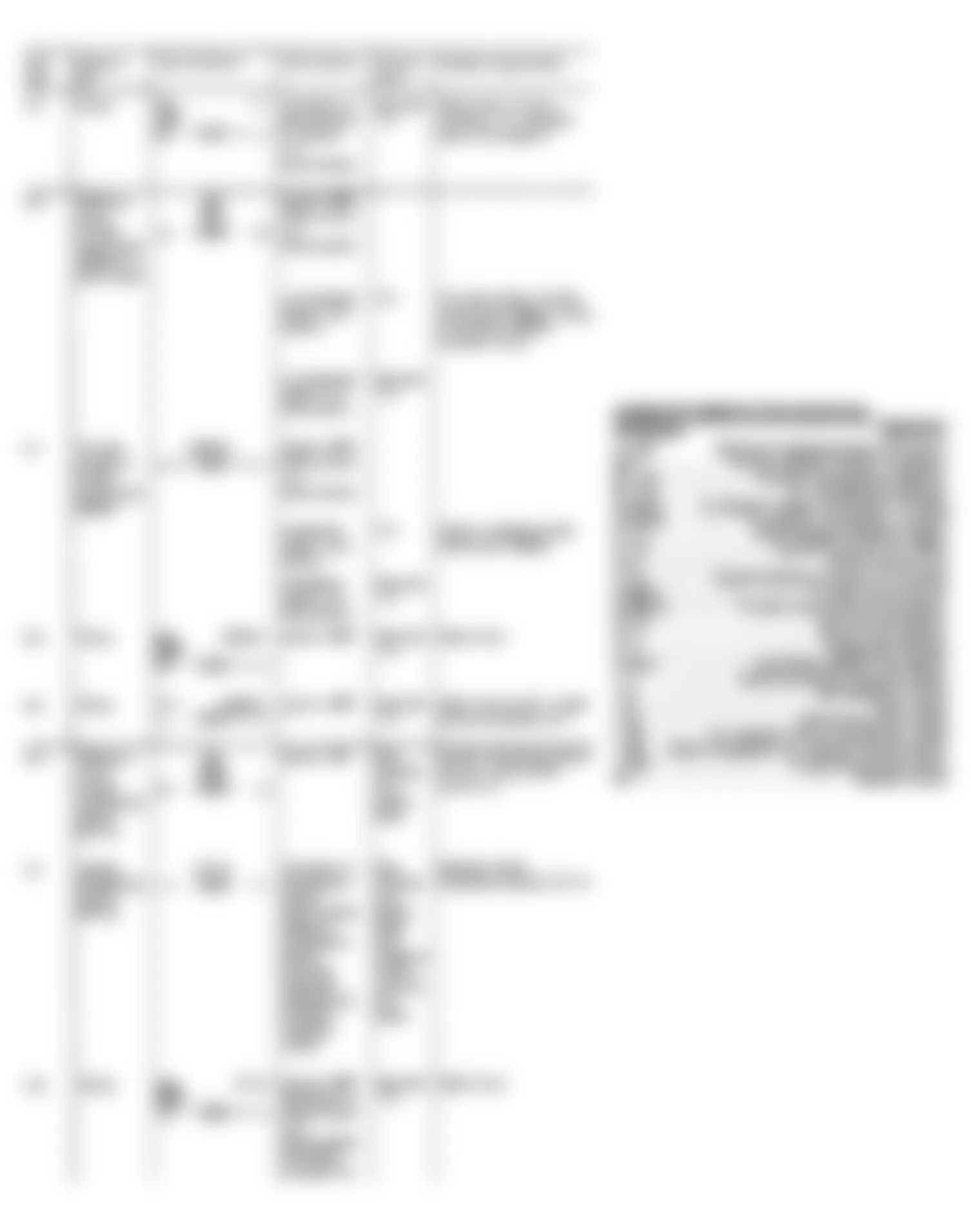
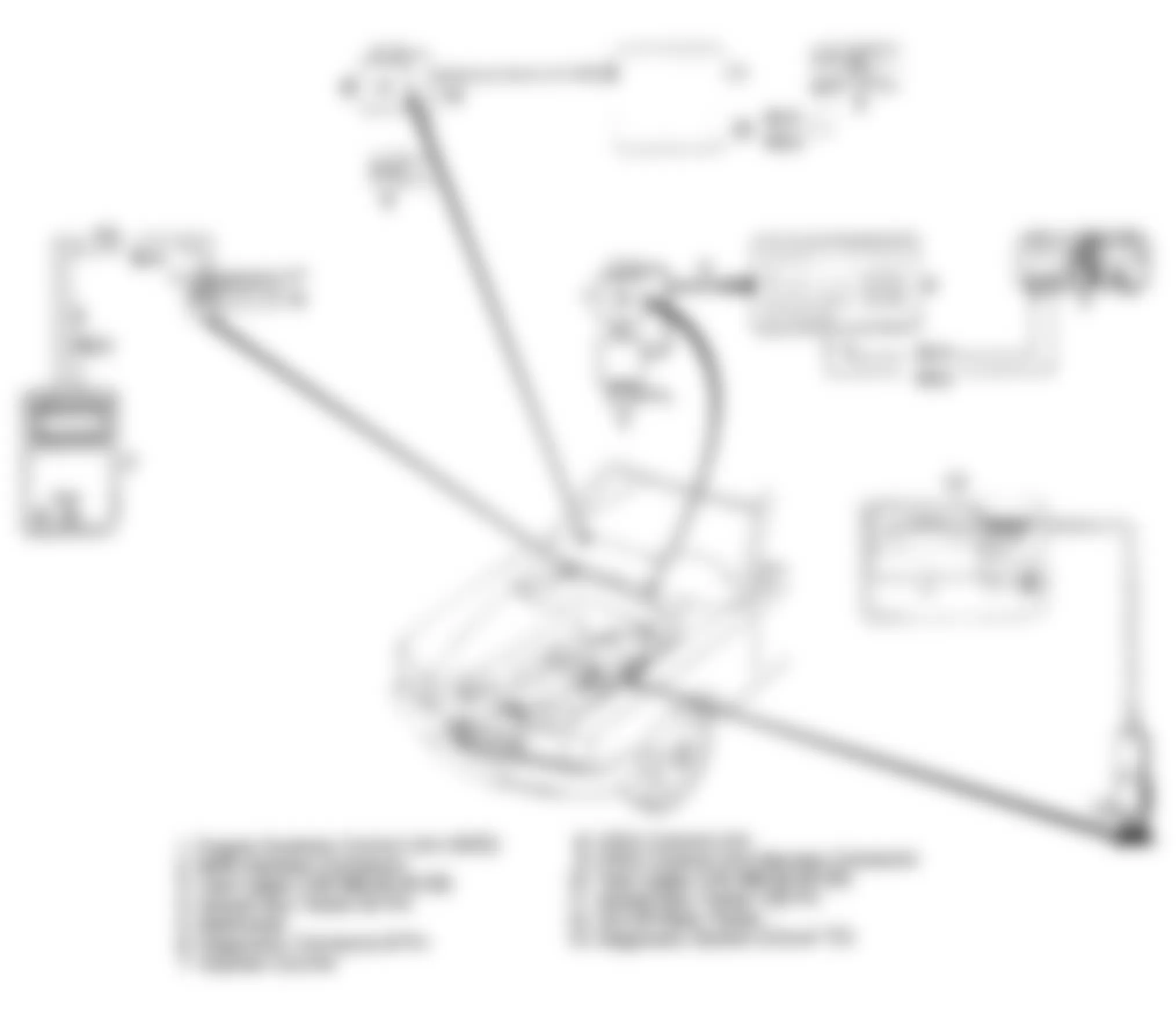
Fig. 8: Mercedes-Benz 300SE 1991 - Component Locations - 6 - Cylinder Test Step Charts (3 of 9)
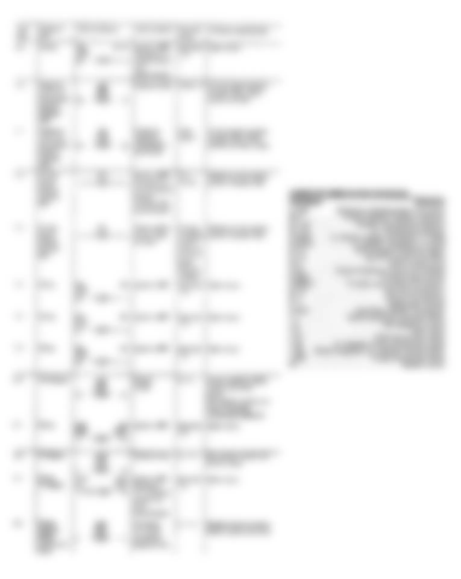
Fig. 9: Mercedes-Benz 300SE 1991 - Component Locations - 6 - Cylinder Test Step Charts (4 of 9)
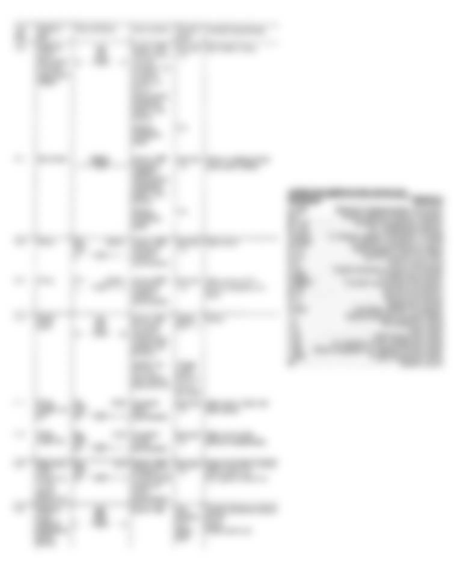
Fig. 10: Mercedes-Benz 300SE 1991 - Component Locations - 6 - Cylinder Test Step Charts (5 of 9)
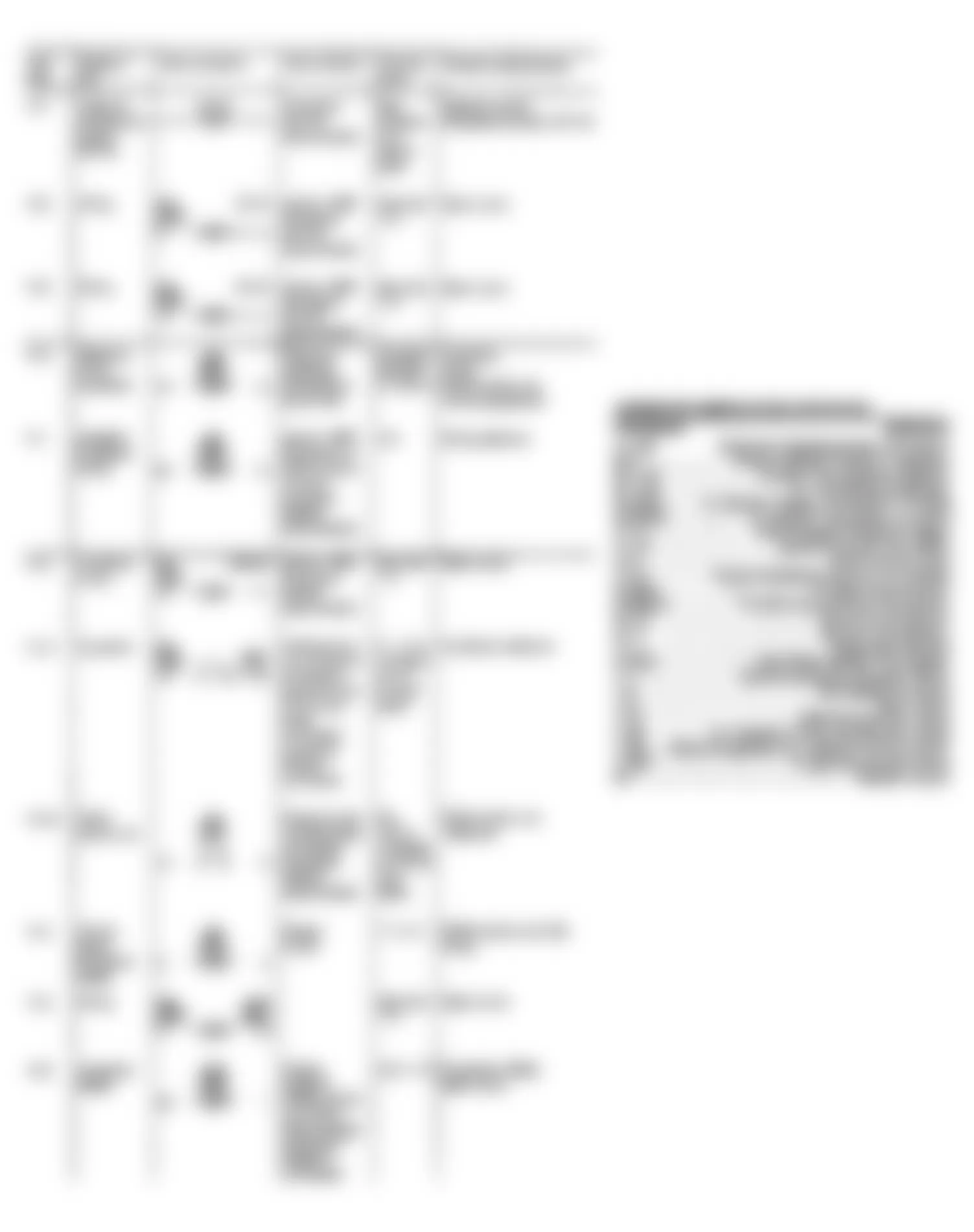
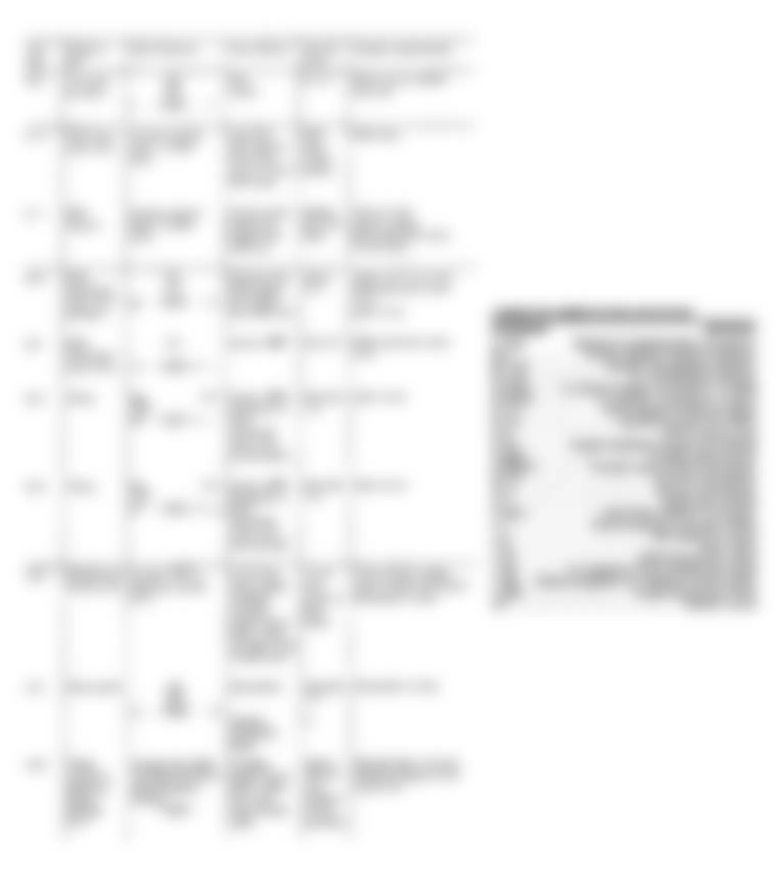
Fig. 11: Mercedes-Benz 300SE 1991 - Component Locations - 6 - Cylinder Test Step Charts (6 of 9)
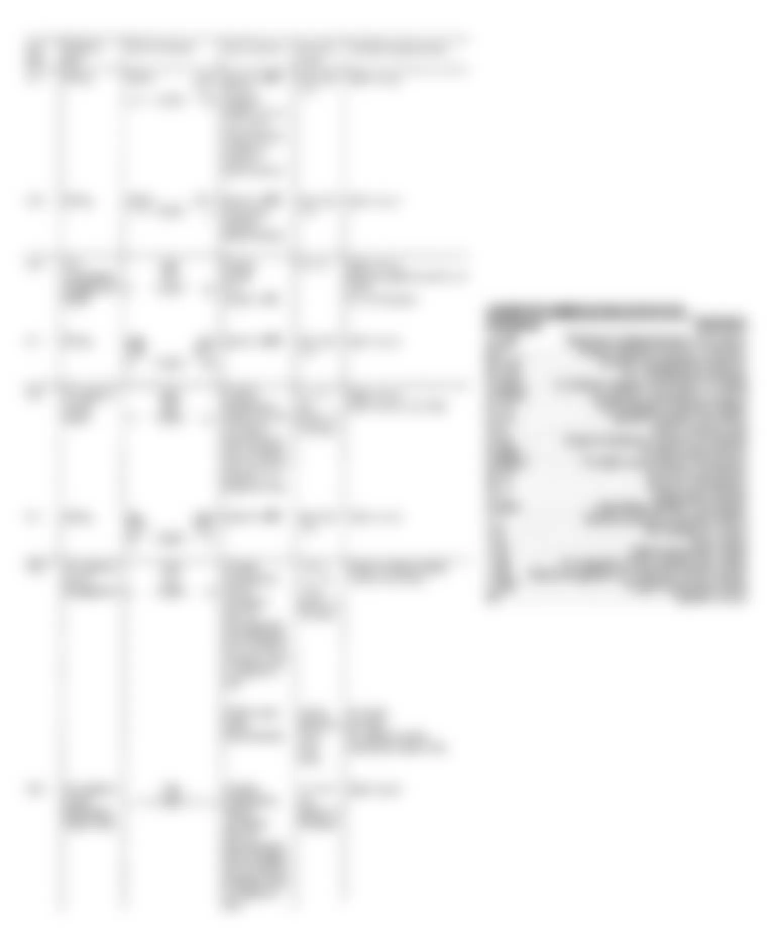
Fig. 12: Mercedes-Benz 300SE 1991 - Component Locations - 6 - Cylinder Test Step Charts (7 of 9)
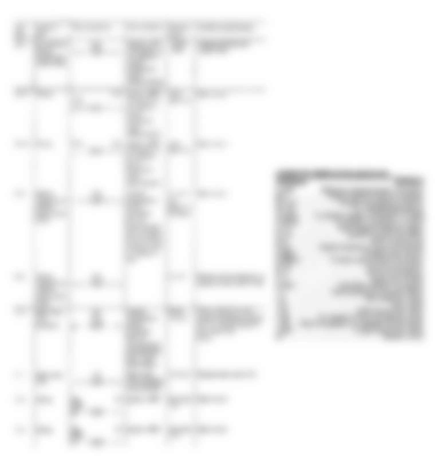
Fig. 13: Mercedes-Benz 300SE 1991 - Component Locations - 6 - Cylinder Test Step Charts (8 of 9)
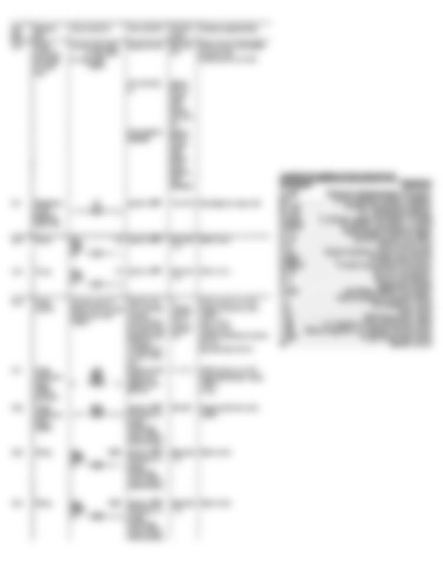
Fig. 14: Mercedes-Benz 300SE 1991 - Component Locations - 6 - Cylinder Test Step Charts (9 of 9)
Mercedes-Benz 300SE 1991 - TEST STEP CHARTS - V8
Mercedes-Benz 300SE 1991 CONNECTOR ABBREVIATIONS DEFINITIONS - V8
Connector Definition A 1p8 Electronic Speedometer Connector B 2 Airflow Sensor Position Indicator B 11/2 Coolant Temperature Sensor B 17/2 Air Temperature Sensor B 18 Altitude Correction Capsule F 1 Fuse No. 7 G 3/2x1 O2 Sensor Heater Connector To MAS G 3/2x2 O2 Sensor Connector To CIS-E K 1/1 Overvoltage Protection Relay N 1/2 Ignition Control Unit (EZL) N 3 CIS-E Control Unit N 16/4 Fuel Pump Relay S 29/2 Throttle Valve Switch S 29/2x1 Throttle Valve Switch Connector W 10 Ground Connection W 11 Ground Connection X 11 Diagnostic Socket X 26 Engine Harness-To-Interior Connector X 53/5 Hall Effect Sensor Connector Y 1 Electrohydraulic Actuator (EHA) Y 6 Idle Speed Air Valve Y 8 Start Valve Y 27 EGR Switchover Valve Y 32 Air Injection Pump Switchover Valve Y 33 Electromagnetic Air Injection Pump Clutch Y 58/1 Purge Switchover Valve 50 Starter Circuit
Fig. 15: Mercedes-Benz 300SE 1991 - Component Locations - Test Step Charts (1 of 4)
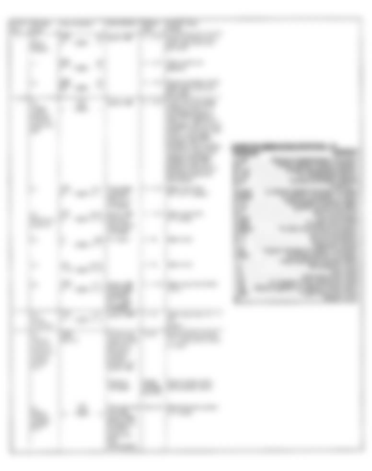
Fig. 16: Mercedes-Benz 300SE 1991 - Component Locations - Test Step Charts (2 of 4)
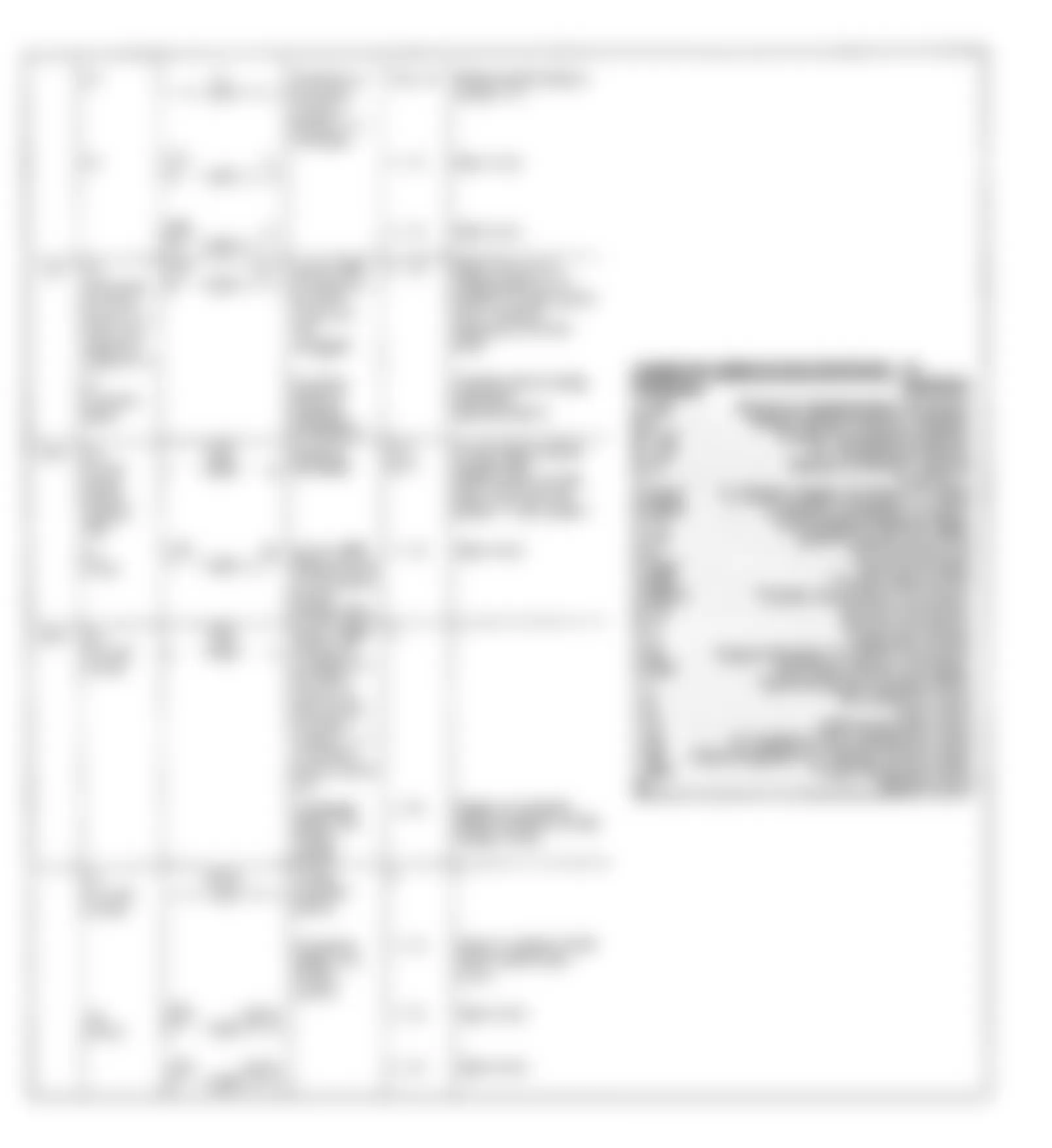
Fig. 17: Mercedes-Benz 300SE 1991 - Component Locations - Test Step Charts (3 of 4)
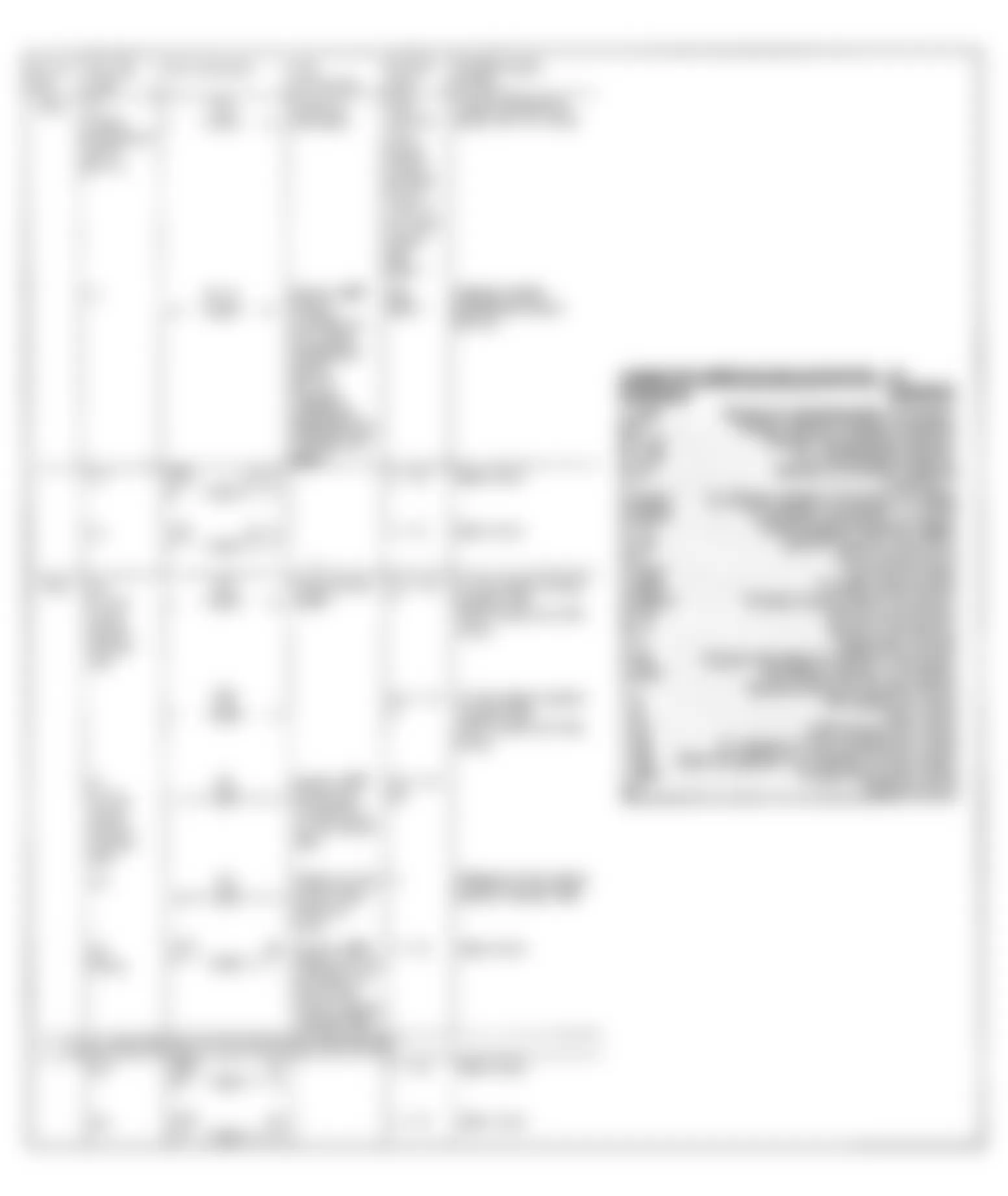
Fig. 18: Mercedes-Benz 300SE 1991 - Component Locations - Test Step Charts (4 of 4)