Mercedes-Benz 500E 1992 - G - TESTS W/CODES - 5.0L 1992-93 ENGINE PERFORMANCE Mercedes-Benz 5.0L V8 LH-SFI Self-Diagnostics
Mercedes-Benz 500E 1992 - INTRODUCTION
| NOTE: | Diagnostic information for 500E is not available. Limited diagnostic information is available for LH-SFI vehicles. |
If no faults were found while performing preliminary inspection, go to RETRIEVING CODES in this article. If no fault codes or only pass codes are present, go to the TESTS W/O CODES in the ENGINE PERFORMANCE section for diagnosis by symptom (i.e., ROUGH IDLE, NO START, etc.).
| NOTE: | All voltage tests should be performed with a Digital Volt-Ohmmeter (DVOM) with a minimum 10-megohm input impedance, unless specifically stated different in testing procedures. |
Mercedes-Benz 500E 1992 - SELF-DIAGNOSTIC SYSTEM
| NOTE: | When diagnosing vehicle, read faults before starting diagnostic work. During some testing procedures, components are disconnected with engine running causing simulated faults. Ensure faults are recorded before starting diagnostic work to ensure only actual faults are diagnosed. |
Mercedes-Benz 500E 1992 - LH-SFI
The LH-SFI system is equipped with a self-diagnostic capability for trouble shooting. There are 2 methods of retrieving diagnostic information. Vehicles can be tested reading an on/off ratio output as a percentage to identify malfunctioning components or systems, or vehicles can be tested reading stored Diagnostic Trouble Codes (DTC's).
Stored DTC'S are different depending on which module is being tested. DTC's can be retrieved from LH-SFI control unit, EZL/AKR ignition control unit, base module, Electronic Accelerator control module, Cruise Control/Idle Speed Control module, and diagnostic module. Diagnostic information can be retrieved using Pulse Counter (124 589 19 21 00) and Pulse Counter Adapter (140 589 14 63 00) or On/Off Ratio Tester (909 589 09 21 00).
Mercedes-Benz 500E 1992 - PRETEST CONDITIONS
Start and run engine until engine oil temperature is 176?F (80?C). Turn air conditioning off. Ensure shift lever is in Park. Check all fuses and replace as necessary. Verify battery voltage is 11-14 volts.
Mercedes-Benz 500E 1992 - RETRIEVING CODES
| NOTE: | On LH-SFI vehicles, on/off ratio output is used to diagnose intermittent problems. On all LH-SFI vehicles, Diagnostic Trouble Codes (DTC's) are used to diagnose hard failures. |
Mercedes-Benz 500E 1992 - LH-SFI
| NOTE: | Before using Diagnostic Trouble Codes (DTC's) to diagnose vehicle, LH-SFI control unit must first be allowed to display on/off ratio through On/Off Ratio Tester (909 589 00 21 00). |
Mercedes-Benz 500E 1992 - On/Off Ratio Output (LH-SFI)
- Turn ignition off. Perform pretest conditions. See PRETEST CONDITIONS. Connect On/Off Ratio Tester (909 589 00 21 00) to diagnostic connector located on left fender apron. See Fig. 1 . Malfunctions are distinguished between failures which occur with ignition on, engine off and with engine idling.
- Only on/off ratio readouts can distinguish between failures which occur with ignition on, engine off and with engine idling. Turn ignition on with engine off or allow engine to idle. Record on/off ratio. See appropriate table under LH-SFI under ON/OFF RATIO IDENTIFICATION.
Mercedes-Benz 500E 1992 - Diagnostic Trouble Code (DTC LH-SFI)
- Turn ignition off. Perform pretest conditions. See PRETEST CONDITIONS. Before using DTC's to diagnose vehicle, LH-SFI control unit must first be allowed to display on/off ratio through On/Off Ratio Tester (909 589 00 21 00). See ON/OFF RATIO OUTPUT (LH-SFI) under RETRIEVING CODES.
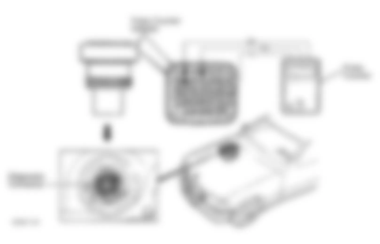
- Connect Pulse Counter Adapter (140 589 14 63 00) to diagnostic connector located in right rear corner of engine compartment. Connect Pulse Counter (124 589 19 21 00) to pulse counter adapter. See Fig. 1 . Connect Red wire of pulse counter to pulse counter adapter terminal No. 3. Connect Black wire of pulse counter to pulse counter adapter terminal No. 1.
- Pulse counter Yellow wire is connected to pulse counter adapter depending on which module is being tested. DTC's are different for each module on vehicle. See PULSE COUNTER CONNECTION/ADAPTER IDENTIFICATION table.
Mercedes-Benz 500E 1992 PULSE COUNTER CONNECTION/ADAPTER IDENTIFICATION
| Module | Adapter Terminal |
| Base Module (1) | No. 8 |
| Cruise Control/Idle Speed Control Module (2) | No. 7 |
| Diagnostic Module (3) | No. 19 |
| Electronic Accelerator Control Module (4) | No. 7 |
| EZL/AKR Ignition Control Unit | No. 17 |
| LH Control Unit | No. 4 |
| (1) | Base module will identify voltage supply malfunctions, A/C clutch, poly-V-belt slipping and module box temperature. | | (2) | Vehicles without Acceleration Slip Regulation (ASR). | | (3) | Diagnostic module will identify malfunctions for all modules. | | (4) | Vehicles equipped with Acceleration Slip Regulation (ASR). | |
Fig. 1: Mercedes-Benz 500E 1992 - Component Locations - Connecting Pulse Counter (LH-SFI Vehicles)
- After connecting Yellow wire to proper pulse counter adapter terminal, U-BATT LED on pulse counter display will illuminate if equipment is properly connected. If U-BATT LED illuminates, go to next step. If U-BATT LED does not illuminate, check pulse counter fuse. Replace as necessary. If pulse counter fuse is okay, check wiring harness between diagnostic connector and vehicle wiring harness. Repair wiring as necessary.
- Start engine and idle. Press START button on pulse counter for 2-4 seconds maximum. Pressing push button longer than 2-4 seconds will erase code in memory. Read pulse output on pulse counter. If pulse counter displays "1", no faults are stored. If pulse counter displays a number greater than "1", faults are stored.
- Press start button again for 2-4 seconds. If more fault codes are stored, pulse counter will display next code. Continue pressing start button for 2-4 seconds at a time until pulse counter displays first fault again. Record all fault codes. See appropriate table under LH-SFI FAULT CODE IDENTIFICATION to identify fault code.
Mercedes-Benz 500E 1992 - LH-SFI FAULT CODE IDENTIFICATION
Mercedes-Benz 500E 1992 BASE MODULE FAULT CODE IDENTIFICATION
| Fault Code | Malfunctioning Component/System |
| 1 | (1) |
| 5 | Maximum Permissible Temperature In Module Box Exceeded |
| 6 | A/C Compressor Electromagnetic Clutch Blocked |
| 7 | Poly-V-Belt Slipping |
| 9 | Voltage Supply For LH-SFI Control Unit Interrupted |
| 10 | Voltage Supply For LH-SFI Control Unit Interrupted Or Voltage Supply For Fuel Injectors Interrupted |
| 11 | Voltage Supply For Accessory Equipment Control Units Interrupted |
| 12 | Voltage Supply For ABS Control Unit Or ABS/ASR Control Unit Interrupted |
| 15 | Voltage Supply For Automatic Transmission Kickdown Valve Interrupted |
| 16 | Voltage Supply For A/C Compressor Electromagnetic Clutch Interrupted |
| 17 | Voltage Supply For Module Box Blower Motor Interrupted |
| |
Mercedes-Benz 500E 1992 CRUISE CNTRL/IDLE SPEED CNTRL MOD FAULT CODE ID
| Fault Code | Malfunctioning Component/System |
| 1 | (1) |
| 2 | Cruise Control/Idle Speed Control Unit |
| 3 | Cruise Control/Idle Speed Control Actuator |
| 4 | Cruise Control Switch |
| 5 | Stop Light Switch |
| 6 | Starter Lock-Out/Backup Light Switch |
| 7 | Controller Area Network (CAN) Data Bus |
| 8 | Left Front Speed Sensor |
| 9 | Leat Rear Speed Sensor |
| 10 | TNA (Engine Speed) Signal |
| 11 | Fuel Safety Shut-Off To LH-SFI Control Unit |
| 12 | Cruise Control/Idle Speed Control Unit Voltage Supply |
| |
Mercedes-Benz 500E 1992 DIAGNOSTIC MODULE FAULT CODE IDENTIFICATION
| Fault Code | Malfunctioning Component/System |
| 1 | (1) |
| 2 | Oxygen Sensor Inoperative |
| 3 | Lambda Control Inoperative |
| 4 | Air Injection Inoperative |
| 5 | Exhaust Gas Recirculation (EGR) Inoperative |
| 6 | Ildle Speed Control Inoperative |
| 7 | Ignition System Failure |
| 8 | Coolant Temperature Sensor Open Or Short Circuit |
| 9 | Intake Air Temperature Sensor Open Or Short Circuit |
| 10 | Voltage At Air Mass Sensor Too High Or Low |
| 11 | TN (RPM) Signal Defective |
| 12 | Oxygen Sensor Heater Open Or Short Circuit |
| 13 | Camshaft Position Sensor Signal From EZL/AKR Ignition Control Unit Defective |
| 14 | Intake Manifold Pressure At Start Too Low |
| 15 | Full Throttle Information Defective |
| 16 | Idle Speed Information Defective |
| 17 | Controller Area Network (CAN) Data Exchange Malfunction Between Control Units |
| 18 | Adjustable Camshaft Timing Solenoid Open Or Short Circuit |
| 19 | Fuel Injectors Open Or Short Circuit Or Emission Control System Adaptation At Limit |
| 20 | Speed Signal Missing |
| 21 | Purge Switchover Valve Open Or Short Circuit |
| 22 | Camshaft Position Sensor Signal Defective |
| 23 | Intake Manifold Pressure With Engine Running Too Low |
| 24 | Starter Ring Gear Segments Defective |
| 25 | Knock Sensors Defective |
| 26 | Upshift Delay Switchover Valve Open Or Short Circuit |
| 27 | Coolant Temperature Sensor Deviation Between Sensor Circuit No. 1 & Sensor Circuit No. 2 |
| 28 | Coolant Temperature Sensor (Coolant Temperature Change Monitor) |
| |
Mercedes-Benz 500E 1992 ELECTRONIC ACCELERATOR CNTRL MODULE FAULT CODE ID
| Fault Code | Malfunctioning Component/System |
| 1 | (1) |
| 2 | Electronic Accelerator Control Unit |
| 3 | Electronic Accelerator Actuator |
| 4 | Cruise Control Switch |
| 5 | Stop Light Switch |
| 6 | Starter Lock-Out/Backup Light Switch |
| 7 | Controller Area Network (CAN) Data Bus |
| 8 | Left Front Speed Sensor |
| 9 | Left Rear Speed Sensor |
| 10 | TNA (Engine Speed) Signal |
| 11 | Fuel Safety Shut-Off To LH Control Unit |
| 12 | Electronic Accelerator Control Unit Voltage Supply |
| 14 | Idle Speed Control Switch |
| |
Mercedes-Benz 500E 1992 EZL/AKR IGNITION CONTROL UNIT FAULT CODE ID
| Fault Code | Malfunctioning Component/System |
| 1 | (1) |
| 2 | Maximum Retard Setting On At Least One Cylinder Has Been Reached |
| 3 | (2) |
| 4 | Load Sensor In EZL/AKR Ignition Control Unit Defective |
| 5 | Knock Sensor No. 1 Or No. 2 Defective |
| 6 | Camshaft Position Sensor Defective |
| 7 | Knock Control Output Switch In EZL/AKR Ignition Control Unit Defective |
| 8 | Transmission Overload Protection Switch Does Not Close |
| 9 | Transmission Overload Protection Switch Does Not Open |
| 10 | (2) |
| 11 | Reference Resistor Defective |
| 12 | TN (Engine RPM) Signal Is Outside Tolerance Range |
| 13-14 | (2) |
| 15 | Ignition Coil No. 1 Output From EZL/AKR Ignition Control Unit Defective Or Primary Winding Of Ignition Coil Has An Open Circuit |
| 16 (3) | Ignition Coil No. 2 Output From EZL/AKR Ignition Control Unit Defective Or Primary Winding Of Ignition Coil Has An Open Circuit |
| 17 | Crankshaft Position Sensor Defective |
| 18 (3) | Magnets For Crankshaft Position Sensor Not Recognized |
| 19 | (2) |
| 20 | EZL/AKR Ignition Control Unit Malfunction Memory Defective |
| 21 | Load Sensor In EZL/AKR Ignition Control Unit Defective (Recognized With Engine Running) |
| 22-25 | (2) |
| 26 | EZL/AKR Ignition Control Unit Data Exchange Malfunction |
| 27 | LH-SFI Control Unit Data Exchange Malfunction |
| 28 | Electronic Accelerator Control Unit Data Exchange Malfunction |
| 29-33 | (2) |
| 34 | Ignition Misfire Cylinder No. 1 |
| 35 | Ignition Misfire Cylinder No. 5 |
| 36 | Ignition Misfire Cylinder No. 3 (6-Cylinder) |
| 36 | Ignition Misfire Cylinder No. 4 (V8) |
| 37 | Ignition Misfire Cylinder No. 6 (6-Cylinder) |
| 37 | Ignition Misfire Cylinder No. 8 (V8) |
| 38 | Ignition Misfire Cylinder No. 2 (6-Cylinder) |
| 38 | Ignition Misfire Cylinder No. 6 (V8) |
| 39 | Ignition Misfire Cylinder No. 4 (6-Cylinder) |
| 39 | Ignition Misfire Cylinder No. 3 (V8) |
| 40 | Ignition Misfire Cylinder No. 7 (V8) |
| 41 | Ignition Misfire Cylinder No. 2 (V8) |
| |
Mercedes-Benz 500E 1992 LH-SFI CONTROL UNIT FAULT CODE IDENTIFICATION
| Fault Code | Malfunctioning Component/System |
| 1 | (1) |
| 2 | Coolant Temperature Sensor Open Or Short In Circuit No. 1 (Terminal No. 31 On LH Control Unit Connector No. 2) |
| 3 | Coolant Temperature Sensor Open Or Short In Circuit No. 2 (Terminal No. 18 On LH Control Unit Connector No. 2) |
| 4 | Voltage At Air Mass Sensor Hot-Wire Too Low Or High, Or Open Ground Wire At Air Mass Sensor |
| 5 | (2) |
| 6 | (2) |
| 7 | RPM (TN) Signal Incorrect Or Open Or Short Circuit |
| 8 | Camshaft Position Sensor Signal Open Or Short Circuit |
| 9 | Starter Signal Missing |
| 10 | Idle Speed Recognition From Electronic Accelerator Module Or Cruise Control/Idle Speed Control Module Short Circuit |
| 11 | Air Injection System Open Or Short Circuit |
| 12 | Burn-Off Control For Air Mass Sensor Open Or Short Circuit |
| 13 | Intake Air Temperature Sensor Open Or Short Circuit |
| 14 | (2) |
| 15 | (2) |
| 16 | EGR Switchover Valve Open Or Short Circuit |
| 17 | No Data Transmission From Electronic Accelerator Module Or Cruise Control/Idle Speed Control Module |
| 18 | No Data Transmission From EZL/AKR Ignition Control Unit |
| 19 | (2) |
| 20 | No Data Transmission From LH Control Unit |
| 21 | Oxygen Sensor Open Circuit |
| 22 | Oxygen Sensor Heater Open Or Short Circuit |
| 23 | Purge Switchover Valve Open Or Short Circuit |
| 24 | Adjustable Camshaft Timing Solenoid Or Right Adjustable Camshaft Timing Solenoid Open Or Short Circuit |
| 25 (3) | Left Adjustable Camshaft Timing Solenoid Open Or Short Circuit |
| 26 | (2) |
| 27 | Fuel Injector Open Or Short Circuit |
| 28 | LH Control Unit Coding Open Circuit |
| |
Mercedes-Benz 500E 1992 - CLEARING CODES LH-SFI
- Disconnecting vehicle battery will not erase codes. Connect Pulse Counter Adapter (140 589 14 63 00) to diagnostic connector located in right rear corner of engine compartment. Connect Pulse Counter (124 589 19 21 00) to pulse counter adapter. See Fig. 1 . Connect Red wire of pulse counter to pulse counter adapter terminal No. 3. Connect Black wire of pulse counter to pulse counter adapter terminal No. 1.
- Pulse counter Yellow wire is connected to pulse counter adapter depending on which module is being cleared. See PULSE COUNTER CONNECTION/ADAPTER IDENTIFICATION table.
Mercedes-Benz 500E 1992 PULSE COUNTER CONNECTION/ADAPTER IDENTIFICATION
| Module | Adapter Terminal |
| Base Module | No. 8 |
| Cruise Control/Idle Speed Control Module (1) | No. 7 |
| Diagnostic Module | No. 19 |
| Electronic Accelerator Control Module (2) | No. 7 |
| EZL/AKR Ignition Control Unit | No. 17 |
| LH Control Unit | No. 4 |
| (1) | Vehicles without Acceleration Slip Regulation (ASR). | | (2) | Vehicles equipped with Acceleration Slip Regulation (ASR). | |
- After connecting Yellow wire to proper pulse counter adapter terminal, U-BATT LED on pulse counter display will illuminate if equipment is properly connected. If U-BATT LED illuminates, go to next step. If U-BATT LED does not illuminate, check pulse counter fuse. Replace as necessary. If pulse counter fuse is okay, check wiring harness between diagnostic connector and vehicle wiring harness. Repair wiring as necessary.
- Turn ignition on. Press START button on pulse counter for 2-4 seconds maximum. Wait 3 seconds. Press START button on pulse counter for 6-8 seconds. Turn ignition off and wait 30 seconds. Each code stored in must be erased individually. Repeat procedure for other stored fault codes. When pulse counter displays "1", no faults are stored. Disconnect test equipment.
Mercedes-Benz 500E 1992 - ON/OFF RATIO DIAGNOSIS ON/OFF RATIO IDENTIFICATION LH-SFI
Mercedes-Benz 500E 1992 LH-SFI CNTRL UNIT ON/OFF RATIO I.D. (IGN ON, ENG OFF)
| On/Off Ratio | Malfunctioning Component/System |
| 0 (1) | Open Circuit In Voltage Supply From Diagnostic Connector Terminal No. 3 |
| 10 | Idle Speed Recognition Inactive |
| 20 | Full Load Recognition Inactive |
| 30 | Coolant Temperature Less Than 158?F (70?C) or Greater Than 230?F (110?C) |
| 40 | Not Used |
| 50 | Input Signals Okay (No Malfunctions) |
| 60 | TN (RPM) Signal Or Camshaft Position Sensor Not Present While Starting |
| 70 | Starter Engaged |
| 80 | Controller Area Network (CAN) Defective |
| 90 | Fuel Safety Shutoff Active |
| (1) | Diagnostic connector is located in right rear corner of engine compartment. | |
Mercedes-Benz 500E 1992 LH-SFI CNTRL UNIT ON/OFF RATIO I.D. (ENG IDLING)
| On/Off Ratio | Malfunctioning Component/System |
| 0 | Short Circuit To Battery Positive In Wire For Test Connection (Diagnostic Connector Terminal No. 3) |
| 10 | Idle Speed Recognition Applied Constantly |
| 20 | Output Of Fuel Injectors Or One Or More Fuel Injectors Has An Open Circuit |
| 30 | Coolant Temperature Sensor |
| 40 | Air Mass Sensor Hot-Wire |
| 50 (1) | O2 Sensor Not Operational Or Defective |
| 60 | Camshaft Position Sensor |
| 70 | TN (RPM) Signal |
| 80 | Controller Area Network (CAN) Defective |
| 90 | Vehicle Speed Signal |
| 95 (2) | Deceleration Fuel Shut-Off Active |
| 100 | No Voltage At LH-SFI control unit. |
| (1) | If needle oscillates on on/off ratio tester, all monitored signals are okay. | | (2) | No malfunction is indicated. LH-SFI control unit is in deceleration fuel shut-off mode. | |