Mercedes-Benz C280 1996 - FUSES & CIRCUIT BREAKERS Fuses & Circuit Breakers 1994-96 Mercedes-Benz
Mercedes-Benz C280 1996 - IDENTIFICATION FUSE BOX LOCATION
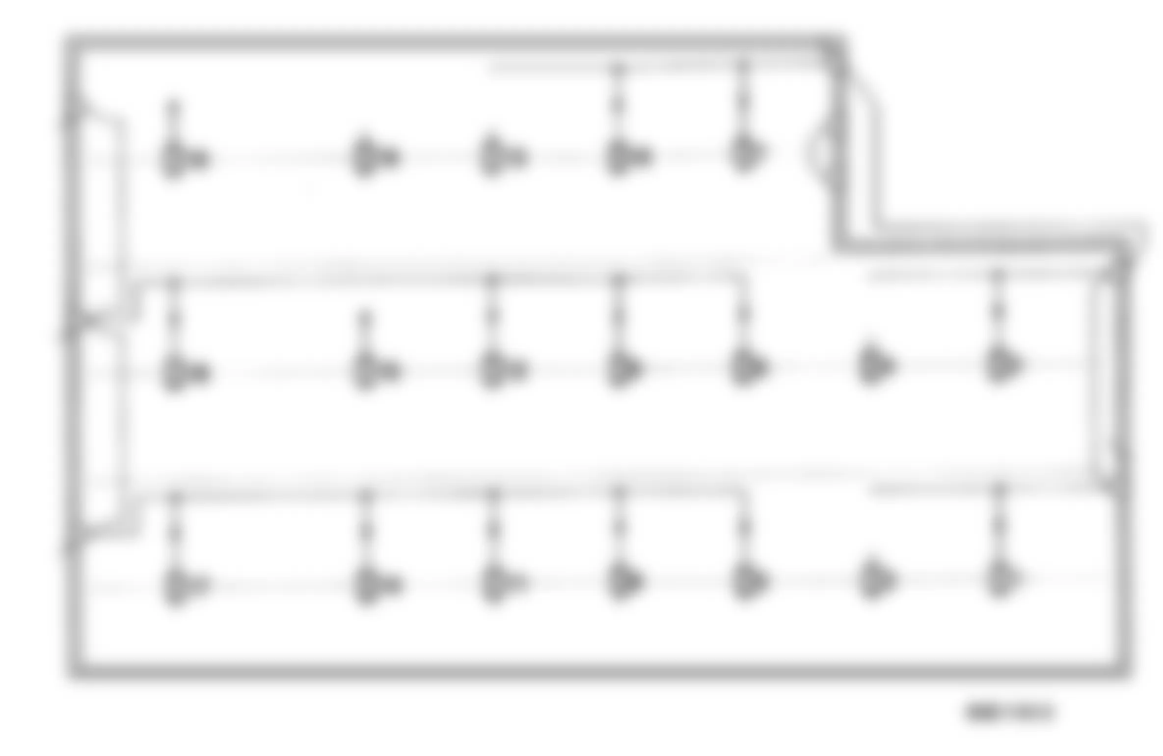
The fuse box is located in the engine compartment. The fuse specifications are on a label on the fuse box lid. Fuse Boxes (F1/1, F2 and F3) are installed in the Fuse and Relay Box.
NOTE: With the fuse boxes tilted up, the voltage supply to 18-fuse box (F3) is interrupted.
Mercedes-Benz C280 1996 - FUSE BOX IDENTIFICATION

Fig. 1: Mercedes-Benz C280 1996 - Component Locations - Fuse Box Identification
WARNING: Always disconnect battery ground cable before servicing "high-current fuses. It is recommended that "high-current" fuses be replaced by a qualified technician.
- 1 - 7.5 Amp Low Beam Right
- 2 - 15 Amp Glove Compartment Light, Radio, Cigar Lighter
- 3 - 10 Amp Seat Belt/Keys/Lights Warning Module, A/C Pushbutton Control Module, REST Time Limit Relay Module
- 4 - 15 Amp Clock Warning Buzzer
- 5 - 20 Amp Fanfare Horns, Seat Belt/Keys/Lights Warning Module, A/C Pushbutton Control Module, REST Time Limit Relay Module
- 6 - 7.5 Amp Turn Signal/Hazard Lamps
- 7 - 7.5 Amp Low Beam Left
- 8 - 7.5 Amp Rear Window Defroster Switch
- 9 - 7.5 Amp Illumination, Cigar Lighter, Illumination License Plate Instrument Cluster
- 10 - Not Used
- 11 - 7.5 Amp Auxiliary Fan Relay Module (A/C), A/C Pushbutton Control
- 12 - 10 Amp Stop Lamp Switch, Instrument Cluster, Exterior Lamp Failure Monitoring Module, Reference Resistor Criuse Control Amplifier, Cruise Control Switch ASR Snow Chain Switch
- 13 - 30 Amp Auxiliary Fan Relay Module
- 14 - 30 Amp A/C System Blower
- 15 - 30 Amp Headlamp Flasher Switch, Headlamp Wiper/Washer Relay Windshield Washer Pump, Wiper Motor
- 16 - 30 Amp Rear Window Defroster
- 17 - 40 Amp AIR Relay Module
- 18 - 7.5 Amp Parking/Tail/Side Marker Lamps (Left)
- 19 - 7.5 Amp High Beam Right
- 20 - 15 Amp Radio, Heated Seats, Rear Window Sun Shade Motor
- 21 - 10 Amp Automatic Antenna, Radio
- 22 - 10 Amp Fog Lights
- 23 - 15 Amp Kickdown Cut-Out Relay Module, Adjustable Camshaft Timing Solenoid, Overvoltage Protection Relay Module (9-pole) EGR Switchover Valve, Resonance Intake Manifold Switchover Valve
- 24 - 10 Amp Headlamp Wiper/Washer, Parking/Tail/Side Marker Lamps (Right) Daytime Running Lamp Control Module (Canada)
- 25 - 7.5 Amp High Beam Left, High Beam Indicator Lamp
- 26 - 7.5 Amp SRS MIL Convenience Control Module (Power Windows), Power Seat Relay Module, Cellular Phone
- 27 - 7.5 Amp Entrance/Exit Lamp, Data Link Connector (DTC Readout) Rear Reading Lamp (Left, Right)
- 28 - 7.5 Amp Rear Fog Lamp
- 29 - 15 Amp Power/Heated Outside Mirrors, Power Mirror Control Switch, Backup Lamp, Heated Windshield Washer System
- 30 - 10 Amp Headlamp Wiper/Washer
- 31 - Not Used
- 32 - 7.5 Amp Not Used
- 33 - 15 Amp Front Dome Lamp, Rear Dome Lamp, Trunk Lamp, Vanity Mirror Light, Central Locking System
- 34 - 7.5 Amp Rear Head Restraint Release Switch, Daytime Running Lamp Control Module (Canada)
- 35 - 7.5 Amp Front Dome Lamp, Orthopedic Backrest, ATA Control Module
Mercedes-Benz C280 1996 - REAR FUSE BOX IDENTIFICATION
Fig. 2: Mercedes-Benz C280 1996 - Component Locations - Rear Fuse Box Identification - Trunk
- 1 - 25 Amp Left Front Power Seat: Head Restraint, Backrest, Rear Seat Height
- 2 - 25 Amp Right Front Power Seat: Seat Fore/Aft, Front Seat Height
- 3 - 25 Amp Left Front Power Seat: Seat Fore/Aft, Front Seat Height
- 4 - 25 Amp Right Front Power Seat: Head Restraint, Backrest, Rear Seat Height
- 5 - 25 Amp Audio Power Amplifier
- 6 - 7.5 Amp CD Changer
- 7 - 30 Amp Convenience Control Module (Rear Power Window)
- 8 - Not Used
- 9 - 7.5 Amp Convenience Control Module (Power Seat Relay Module)
- 10 - 30 Amp Convenience Control Module (Front Power Window)
- 11 - 7.5 Amp ATA Control Module
- 12 - 20 Amp Front Seat Heater Control Module
- 13 - 20 Amp Sliding/Pop-up Roof
- 14 - Not Used
- 15 - Not Used
- 16 - Not Used
- 17 - 7.5 Amp Cellular Telephone
- 18 - Not Used
- 19 - Not Used
Mercedes-Benz C280 1996 - RELAY IDENTIFICATION
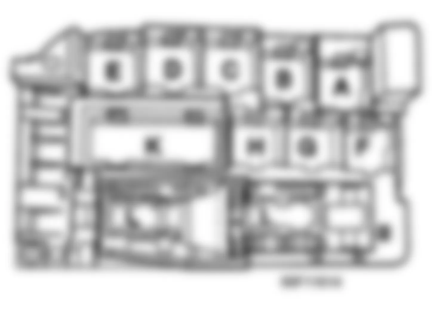
Fig. 3: Mercedes-Benz C280 1996 - Component Locations - Relay Identification
- A - O2S 2 (after TWC) heater Relay Module
- B - ASR Charging Pump Relay Module
- C - Auxiliary Fan Relay Module (Stage 1)
- D - Auxiliary Fan Relay Module (Stage 2)
- E - HCS Relay Module
- F - FAN Relay Module
- G - Blank
- H - AIR Relay Module
- K - Combination Relay (Turn/Hazard Signal, Heated Rear Window, Wiper Motor)
- L - Exterior Lamp Failure Monitoring Module


