NAVIGATION
Crew Chief Wiring Diagram for Ford E-150 XL 2013

List of elements for Crew Chief Wiring Diagram for Ford E-150 XL 2013:
- 5vpwr
- 5vtb
- 7-pin trailer tow connector (under rear bumper)
- Battery junction box (bjb) (left front of engine compt)
- Boo
- Bpp
- Brake
- Brake pedal position (bpp) switch (under left side of dash)
- C110
- C2108
- C219
- C2280b
- C422
- Can+
- Can-
- Cgnd
- Computer data lines system
- Front cigar lighter)
- Fuse 10a
- Fuse 30a
- G200 (right side of dash)
- Gnd
- Gnd-a
- Gnd1
- Hot at all times
- Hot in start or run
- Hs can +
- Hs can -
- Hsc1-a
- Hsc1-c
- Hsc2-a
- Hsc2-c
- Igrun-a
- Igrun-c
- Inline fuse (top center of dash)
- Modem antenna (top center of dash)
- Nca
- Pwr
- Pwr gnd
- Red
- Run start
- Rxd
- S272
- S273
- S274
- Smart junction box (sjb) (except stripped chassis: left kick panel) (stripped chassis: left side of dash)
- Tbo
- Telematics module
- Trailer
- Trailer brake control (tbc) module (top center of dash)
- Txd
- Vb-a
- Vb1
- Vbatt
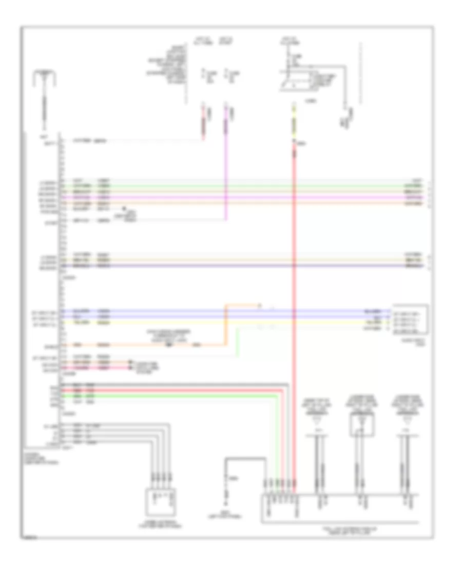
In Dash Computer Wiring Diagram (1 of 2) for Ford E-150 XL 2013
List of elements for In Dash Computer Wiring Diagram (1 of 2) for Ford E-150 XL 2013:
- (main wiring harness, in breakout to audio input jack) s241
- (near top of left "b" pillar) tool link antenna 1
- (under side of roof, near right "b" pillar) tool link antenna 2
- (under side of roof, near right "d" pillar) tool link antenna 3
- 5v usb
- Ant
- Antenna
- Audio input jack
- Batt +
- Battery saver relay
- C gnd
- C2280a
- C2280b
- C2280d
- C2408a
- C2408b
- C2408c
- C2411
- Cbp28
- Cgnd
- Coax cable
- Computer data lines system
- Dme45
- Dtr
- Fuse 10a
- Fuse 20a
- Fuse 5a
- G201 (center of dash)
- G203 (left kick panel)
- Gd115
- Gnd
- Gnd cable
- Hot at all times
- Hot in start
- In-dash computer (center of dash)
- Lf spkr +
- Lf spkr -
- Lr spkr +
- Lr spkr -
- Micro
- Modem antenna (top center of dash)
- Ms can+
- Ms can-
- Nca
- Pwr cable
- Pwr gnd
- Red
- Rf in
- Rf spkr +
- Rf spkr -
- Rme07
- Rme09
- Rme10
- Rme12
- Rme45
- Rme46
- Rr spkr +
- Rr spkr -
- Rxd
- S905
- S906
- Sbp39
- Shield
- Smart junction box (sjb) (except stripped chassis: left kick panel) (stripped chassis: left side of dash)
- St input 2l +
- St input 2l -
- St input 2r +
- St input 2r -
- Start
- Tool link antenna module (near left "b" pillar)
- Txd
- Used) (not
- Vdb06
- Vdb07
- Vme07
- Vme09
- Vme10
- Vme12
- Vme45
- Vme46
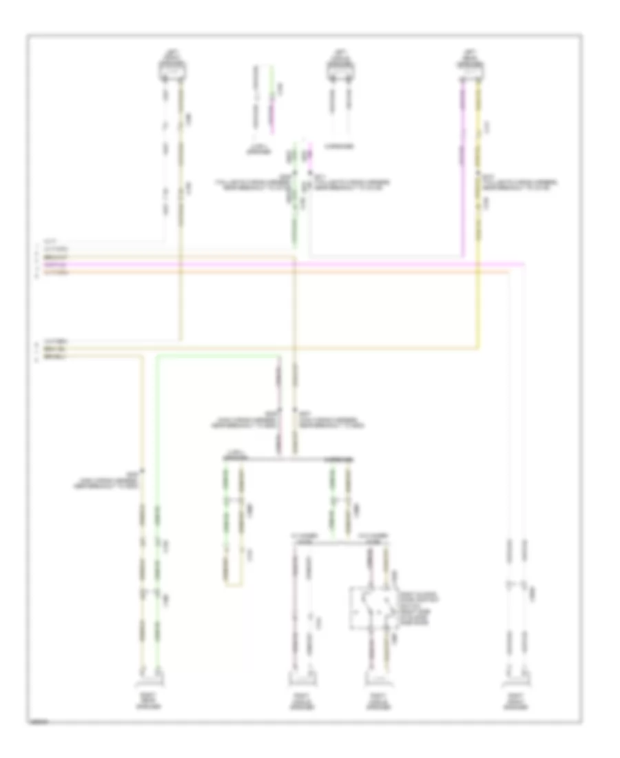
In Dash Computer Wiring Diagram (2 of 2) for Ford E-150 XL 2013
List of elements for In Dash Computer Wiring Diagram (2 of 2) for Ford E-150 XL 2013:
- 2 or 4 speaker
- 6 speaker
- C210
- C268
- C3007
- C3049
- C314
- C316
- C3235
- C406
- C411
- C807
- Left front speaker
- Left middle speaker
- Left rear speaker
- Right front speaker
- Right middle speaker
- Right rear speaker
- Right sliding door contact switch (right side of sliding side door)
- S207 (main wiring harness, near breakout to g200)
- S208 (main wiring harness, near breakout to g200)
- S209 (main wiring harness, near breakout to g200)
- S310 (taillights wiring harness, near breakout to c3135)
- S311 (taillights wiring harness, near breakout to c3135)
- W/ hinged door
- W/o hinged door
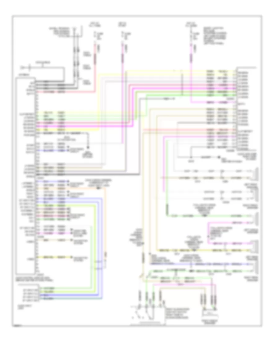
Navigation Wiring Diagram for Ford E-150 XL 2013
List of elements for Navigation Wiring Diagram for Ford E-150 XL 2013:
- (main wiring harness, in breakout to audio input jack) s241
- (main wiring harness, near breakout to g200)
- (main wiring harness, near breakout to g200) s207
- (right side of sliding side door)
- (taillights wiring harness, near breakout to c3135)
- (taillights wiring harness, near breakout to c3135) s311
- Ant
- Antenna
- Audio amplifier (right side of dash)
- Audio control module (acm) (behind center of dash panel)
- Audio input jack
- Batt+
- C210
- C2280a
- C2280b
- C2385a
- C2385b
- C240a
- C240b
- C240c
- C268
- C3007
- C3049
- C314
- C3235
- C406
- C411
- C807
- Cbp28
- Clip detect
- Cme27
- Coax cable
- Computer data lines system
- Dme17
- Dme43
- Dme45
- Fuse 20a
- Fuse 5a
- G201 (center of dash)
- Gd115
- Hot at all times
- Hot in start
- L stereo +
- L stereo -
- Left front speaker
- Left middle speaker
- Left rear speaker
- Lf spkr+
- Lf spkr-
- Lr spkr+
- Lr spkr-
- Mic +
- Mic -
- Mono +
- Mono -
- Ms can+
- Ms can-
- Navigation system
- Nca
- Pwr gnd
- R stereo +
- R stereo -
- Rf in
- Rf spkr+
- Rf spkr-
- Right front speaker
- Right middle speaker
- Right rear speaker
- Right sliding door contact switch
- Rme07
- Rme09
- Rme10
- Rme12
- Rme17
- Rme18
- Rme19
- Rme45
- Rme46
- Rme52
- Rme53
- Rme54
- Rme60
- Rme61
- Rmm23
- Rmn14
- Rr spkr+
- Rr spkr-
- S208 (main wiring harness, near breakout to g200)
- S209
- S216
- S216 (w/ navigation)
- S309
- Satellite radio/ gps antenna (top of right "a" pillar)
- Sbp39
- Sbp40
- Shield
- Smart junction box (sjb) (stripped chassis: left side of dash) (except stripped chassis: left kick panel)
- St input 2l+
- St input 2l-
- St input 2r+
- St input 2r-
- Start
- Swc 2+
- Swc 2-
- Sync radio circuit
- Vdb06
- Vdb07
- Video+
- Video-
- Vme07
- Vme09
- Vme10
- Vme12
- Vme17
- Vme18
- Vme19
- Vme43
- Vme45
- Vme46
- Vme52
- Vme53
- Vme54
- Vme60
- Vme61
- Vmm23
- Vmn14
- W/ hinged door
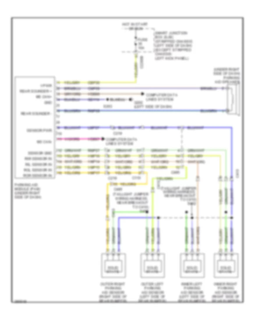
Parking Assistant Wiring Diagram for Ford E-150 XL 2013
List of elements for Parking Assistant Wiring Diagram for Ford E-150 XL 2013:
- (taillight jumper wiring harness, near breakout to c410) s402
- (taillight jumper wiring harness, near breakout to c410) s408
- (under right side of dash) parking aid speaker
- C110
- C219
- C2280b
- C410
- C495
- Cbp35
- Cmp09
- Computer data lines system
- Fuse 10a
- G202 (left side of dash)
- Gd114
- Gnd
- Hot in start or run
- Inner left parking aid sensor (left side of rear bumper)
- Inner right parking aid sensor (right side of rear bumper)
- Lmp07
- Ms can+
- Ms can-
- Outer left parking aid sensor (left side of rear bumper)
- Outer right parking aid sensor (right side of rear bumper)
- Parking aid module (pam) (under right side of dash)
- Rear sounder +
- Rear sounder -
- Ril sensor in
- Rir sensor in
- Rmp07
- Rmp09
- Rol sensor in
- Ror sensor in
- S263
- Sensor gnd
- Sensor pwr
- Smart junction box (sjb) (stripped chassis: left side of dash) (except stripped chassis: left kick panel)
- Solid state
- Vdb06
- Vdb07
- Vmp14
- Vmp15
- Vmp16
- Vmp17
- Vpwr
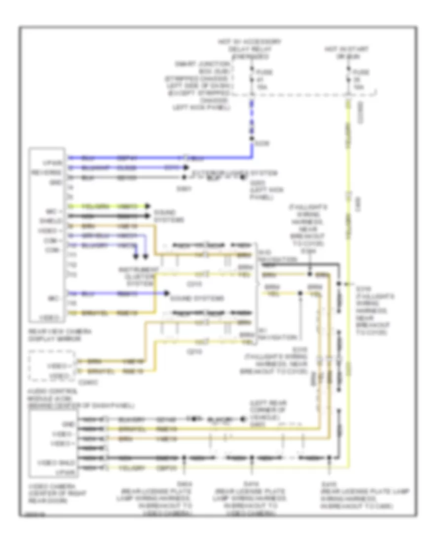
Rear Camera Wiring Diagram for Ford E-150 XL 2013
List of elements for Rear Camera Wiring Diagram for Ford E-150 XL 2013:
- (left rear corner of vehicle) g403
- (rear license plate lamp wiring harness, in breakout to c406)
- (taillights wiring harness, near breakout to c3135) s314
- Audio control module (acm) (behind center of dash panel)
- C210
- C2280d
- C240c
- C315
- C406
- C431
- Cbp35
- Cbp41
- Cls28
- Com +
- Com -
- Dme19
- Dmm13
- Exterior lights system
- Fuse 10a
- Fuse 15a
- G203 (left kick panel)
- Gd133
- Gd149
- Gnd
- Hot in start or run
- Hot w/ accessory delay relay energized
- Instrument cluster system
- Mic +
- Mic -
- Nca
- Rear view camera display mirror
- Reverse
- Rme19
- Rmm13
- S236
- S316 (taillights wiring harness, near breakout to c3135)
- S404 (rear license plate lamp wiring harness, in breakout to video camera)
- S414 (rear license plate lamp wiring harness, in breakout to video camera)
- S415
- S901
- Shield
- Smart junction box (sjb) (stripped chassis: left side of dash) (except stripped chassis: left kick panel)
- Sound systems
- Video +
- Video -
- Video camera (center of right rear door)
- Video shld
- Vmc30
- Vmc31
- Vme19
- Vmm13
- Vpwr
- W/o navigation nca