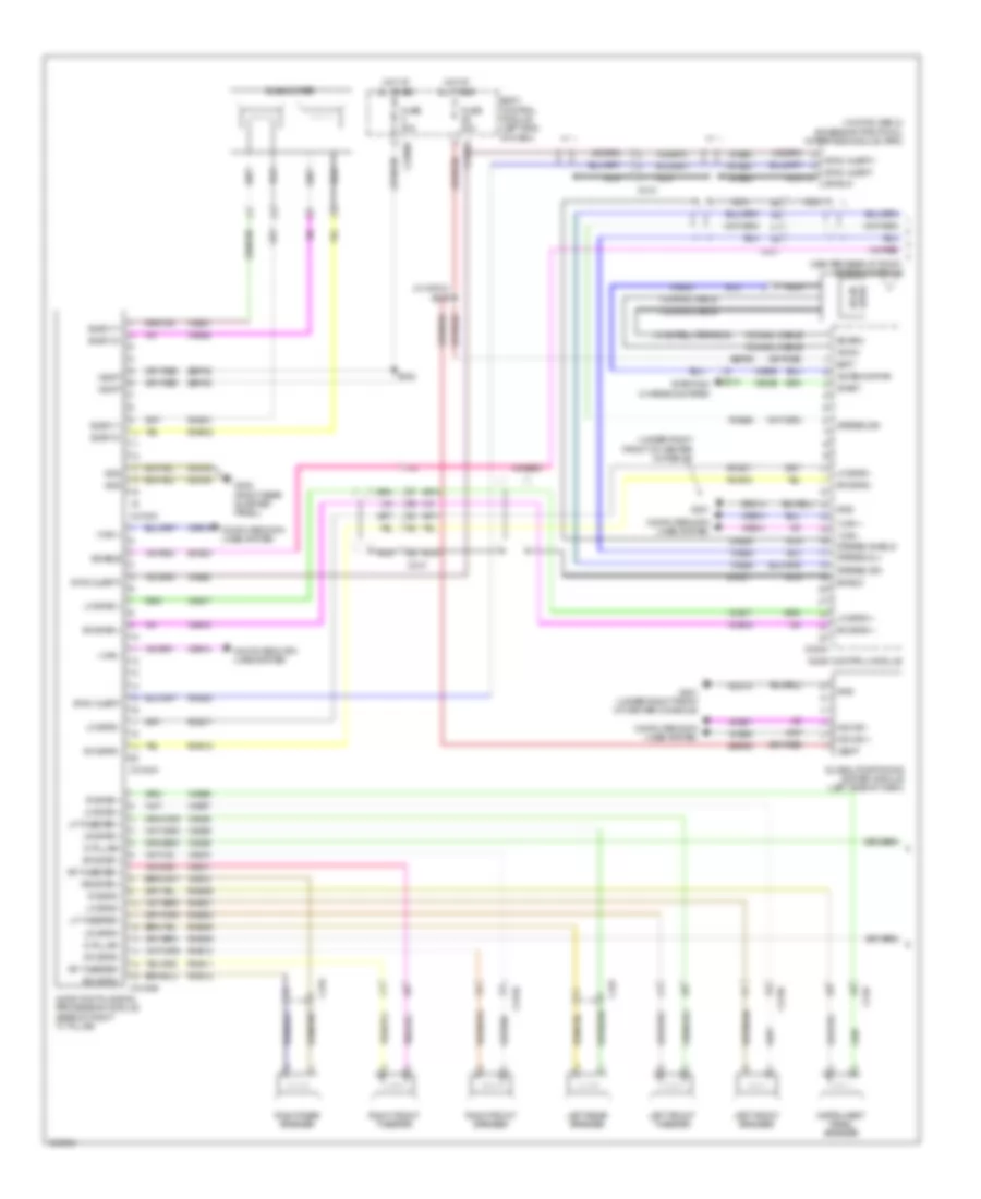
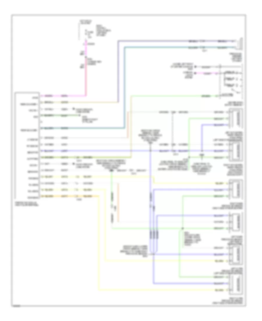
NAVIGATION
Blind Spot Information System Wiring Diagram for Ford Explorer Sport 2014

List of elements for Blind Spot Information System Wiring Diagram for Ford Explorer Sport 2014:
- Address
- Alert
- Body control module (left end of dash)
- C2280d
- C3138
- C3139
- C405
- C406
- C465
- Cbp34
- Computer data lines system
- Crb02
- Crb04
- Driver side exterior rearview mirror
- Except police
- Fuse 10a
- G300 (left kick panel)
- G302 (right rear quarterpanel)
- G400 (base of right "d" pillar)
- Gd351
- Gnd
- Hot in run or start
- Left exterior mirror blind spot (blis)/ cross traffic alert (cta) led
- Left side obstacle detection control module (sod-l) (left quarterpanel)
- Ms can+
- Ms can-
- Nca
- Passenger side exterior rearview mirror
- Police
- Right exterior mirror blind spot (blis)/ cross traffic alert (cta) led
- Right side obstacle detection control module (sod-r) (right quarterpanel)
- Run/start
- S407
- S501
- S602
- Vdb06
- Vdb07
- W/ trailer tow
- W/o trailer tow
Navigation Wiring Diagram, with Sony (1 of 2) for Ford Explorer Sport 2014
List of elements for Navigation Wiring Diagram, with Sony (1 of 2) for Ford Explorer Sport 2014:
- (center rear of roof) antenna module
- (under right front of center console)
- (w/ satellite radio)
- (w/ sync gen 2) accessory protocol interface module (apim)
- (w/ sync) s212
- Am/fm
- Antenna pwr
- Audio control module
- Audio digital signal processing module (base of right "c" pillar)
- Batt
- Body control module (left end of dash)
- C210
- C2280a
- C2280d
- C237
- C240a
- C3138
- C3139
- C3154a
- C3154b
- C3154c
- C316
- C327
- Ce336
- Coaxial cable
- Computer data lines system
- D pillar -
- D pillar+
- Dme17
- Dme45
- Dme80
- Enable
- Fuse 20a
- G201
- G201 (under right front of center console)
- G302 (right rear quarter panel)
- Gd214
- Gd348
- Global positioning system module (left side of dash)
- Gnd
- Hot at all times
- I can +
- I can -
- Instrument panel speaker
- Ip spkr +
- Ip spkr -
- Left front speaker
- Left front tweeter
- Left rear speaker
- Lf spkr +
- Lf spkr -
- Lf tweeter +
- Lf tweeter -
- Lr spkr +
- Lr spkr -
- Ms can +
- Ms can -
- Nca
- Rf spkr +
- Rf spkr -
- Rf tweeter +
- Rf tweeter -
- Right front speaker
- Right front tweeter
- Right rear speaker
- Rme01
- Rme02
- Rme06
- Rme07
- Rme08
- Rme09
- Rme10
- Rme11
- Rme12
- Rme17
- Rme18
- Rme39
- Rme46
- Rme80
- Rr spkr +
- Rr spkr -
- S332
- Sbp05
- Sbp29
- Sdars
- Shield
- Sme23
- Solid state
- Start
- Starting/ charging system
- Stereo 2l+
- Stereo 2r+
- Stereo 2r-
- Stereo shield
- Subw 1+
- Subw 1-
- Subw 2+
- Subw 2-
- Subwoofer
- Sync alert+
- Sync alert-
- V batt
- Vbatt
- Vdb06
- Vdb07
- Vdb13
- Vdb14
- Vme01
- Vme02
- Vme06
- Vme07
- Vme08
- Vme09
- Vme10
- Vme11
- Vme12
- Vme17
- Vme18
- Vme39
- Vme43
- Vme45
- Vme46
- Vme80
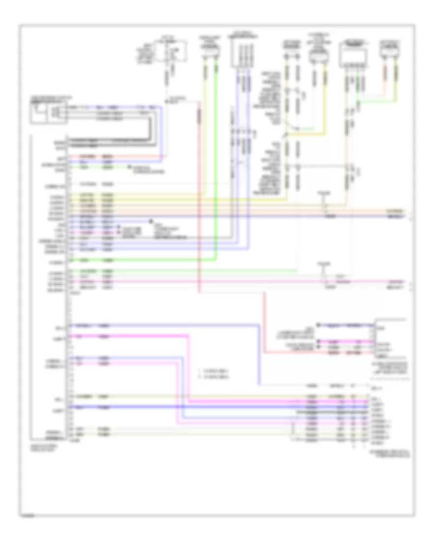
Navigation Wiring Diagram, with Sony (2 of 2) for Ford Explorer Sport 2014
List of elements for Navigation Wiring Diagram, with Sony (2 of 2) for Ford Explorer Sport 2014:
- (body main wiring assembly, near breakout to hs-can joint connector 4) s330
- (under right front of center console) g201
- (w/o sync gen 2) front control/ display interface module
- A/d channel 2
- A/d channel 3
- A/d channel 4
- A/d return
- Alert +
- Alert -
- Audio control module
- Audio input jack (w/o sync)
- Body control module (left end of dash)
- C218b
- C218c
- C2280a
- C2280b
- C240b
- C2414a
- C2414d
- C263
- Clockspring (top of steering column)
- Cls32
- Computer data lines system
- Enable
- Except police
- Exterior lights system
- Front controls interface module (fcim)
- Fuse 10a
- Fuse 15a
- G201 (under right front of center console)
- Gd214
- Gnd
- Hazard
- Hazard switch
- Hot at all times
- Hs can+
- Hs can-
- I can +
- I can -
- Interior lights system
- Left rear d-pillar tweeter
- Left steering wheel switch
- Logic gnd
- Media
- Mute
- Nca
- Phone
- Pnk
- Police
- Ptt
- Red
- Right rear d-pillar tweeter
- Right steering wheel switch
- Rme52
- Rme53
- Rme80
- S203
- S211
- S331 (body main wiring assembly, near breakout to hs-can joint connector 4)
- Sbp09
- Sbp23
- Sdl h
- Sdl l
- Seek +
- Seek -
- Sme23
- St input 2l+
- St input 2r+
- St input 2r-
- Steering column control module (top of steering column)
- Stereo l+
- Stereo l-
- Stereo r+
- Stereo r-
- Sync radio circuit
- Vbatt
- Vdb04
- Vdb05
- Vdb13
- Vdb14
- Vme52
- Vme53
- Vme80
- Vme90
- Vme91
- Vol +
- Vol -
- W/ sync
- W/o sync
Navigation Wiring Diagram, without Sony (1 of 2) for Ford Explorer Sport 2014
List of elements for Navigation Wiring Diagram, without Sony (1 of 2) for Ford Explorer Sport 2014:
- (body main wiring assembly, near breakout to driver's safety belt retractor pretensioner) (w/ premium plus) s323
- (center rear of roof) antenna module
- (w/ premium plus) left quarter panel speaker
- (w/ satellite radio)
- (w/ sync) s212
- (w/o sync) audio input jack
- Accessory protocol interface module
- Alert+
- Alert-
- Am/fm
- Antenna pwr
- Audio control module (acm)
- Batt
- Body control module (left end of dash)
- C2026
- C210
- C211
- C2280a
- C237
- C240a
- C240b
- C3138
- C327
- Ce336
- Coaxial cable
- Computer data lines system
- Dme45
- Dme52
- Dme80
- Fuse 20a
- G201 (under right front of center console)
- Gd214
- Global positioning system module (left side of dash)
- Gnd
- Hot at all times
- I can +
- I can -
- Instrument panel speaker
- Ip spkr +
- Ip spkr -
- Left front speaker
- Left front tweeter
- Left rear speaker
- Lf spkr +
- Lf spkr -
- Lr spkr +
- Lr spkr -
- Ms can +
- Ms can -
- Nca
- Police
- Rf spkr +
- Rf spkr -
- Rme06
- Rme07
- Rme09
- Rme10
- Rme12
- Rme46
- Rme52
- Rme53
- Rme80
- Rr spkr +
- Rr spkr -
- S322 (w/ premium plus) (body main wiring assembly, near breakout to driver's safety belt retractor pretensioner)
- Sbp29
- Sdars
- Sdl h
- Sdl l
- Shield
- St input 2l+
- St input 2r+
- St input 2r-
- Start
- Starting/ charging system
- State solid
- Stereo 2l+
- Stereo 2r+
- Stereo 2r-
- Stereo l +
- Stereo l -
- Stereo r +
- Stereo r -
- Stereo shield
- Vbatt
- Vdb06
- Vdb07
- Vdb13
- Vdb14
- Vme06
- Vme07
- Vme09
- Vme10
- Vme12
- Vme43
- Vme45
- Vme46
- Vme52
- Vme53
- Vme80
- Vme90
- Vme91
- W/ sync gen 1
- W/ sync gen 2
Navigation Wiring Diagram, without Sony (2 of 2) for Ford Explorer Sport 2014
List of elements for Navigation Wiring Diagram, without Sony (2 of 2) for Ford Explorer Sport 2014:
- (top of steering column) steering column control module
- (under right front of center console) g201
- (w/ premium plus) right quarter panel speaker
- A/d channel 2
- A/d channel 3
- A/d channel 4
- A/d return
- Body control module (left end of dash)
- C210
- C218b
- C218c
- C2280a
- C2280b
- C2414a
- C2414d
- C263
- C3139
- C316
- Clockspring (top of steering column)
- Cls32
- Computer data lines system
- Except police
- Exterior lights system
- Front control/ display interface module (fcdim) (w/o sync gen2)
- Front controls interface module (fcim)
- Fuse 10a
- Fuse 15a
- G201 (under right front of center console)
- Gd214
- Gnd
- Hazard
- Hazard switch
- Hot at all times
- Hs can+
- Hs can-
- I can +
- I can -
- Interior lights system
- Left steering wheel switch
- Logic gnd
- Media
- Mute
- Nca
- Phone
- Pnk
- Police
- Ptt
- Red
- Right front speaker
- Right front tweeter
- Right rear speaker
- Right steering wheel switch
- S203
- S211
- S326 (w/ premium plus)
- S327 (w/ premium plus) (body main wiring assembly, near breakout to passenger's load limiting retractor)
- Sbp09
- Sbp23
- Seek +
- Seek -
- Vbatt
- Vdb04
- Vdb05
- Vdb13
- Vdb14
- Vol +
- Vol -
- W/ sync
- W/o sync
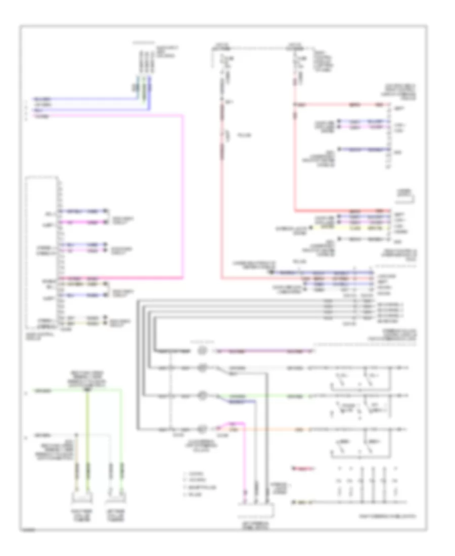
Parking Assistant Wiring Diagram for Ford Explorer Sport 2014
List of elements for Parking Assistant Wiring Diagram for Ford Explorer Sport 2014:
- (backup alarm jumper wiring assembly, near breakout to inner right parking aid sensor) s402
- (body main wiring assembly, near breakout to parking aid module (pam)) (if equipped) s339
- (body main wiring assembly, near breakout to parking aid module (pam)) (if equipped) s340
- (dash panel to headlamp junction wiring assembly, near breakout to g103)
- (under left front of center console) g200
- Auto park
- Autp park
- Body control module (bcm) (left end of dash)
- C210
- C211
- C213
- C2280d
- C406
- Cbp34
- Center stack switch assembly
- Cmp09
- Cmp18
- Computer data lines system
- Fuse 10a
- G400 (base of right "d" pillar)
- Gd351
- Gnd
- Hot in run or start
- Hs can +
- Hs can -
- Interior lights system
- Left active park assist sensor (if equipped) (left side of engine compt)
- Left inner parking aid sensor (left side of rear bumper)
- Left outer parking aid sensor (left side of rear bumper)
- Lf side sn
- Lmp07
- Parking aid module (right quarterpanel)
- Parking aid speaker (left side of dash)
- Rear sounder +
- Rear sounder -
- Rf side sn
- Right active park assist sensor (if equipped) (right side of engine compt)
- Right inner parking aid sensor (right side of rear bumper)
- Right outer parking aid sensor (right side of rear bumper)
- Ril sens
- Rir sens
- Rmp07
- Rmp09
- Rol sens
- Ror sens
- S135 (dash panel to headlamp junction wiring assembly, near breakout to battery junction box (bjb))
- S139
- S328 (w/ rear view camera)
- S404 (backup alarm jumper wiring assembly, near breakout to c4082)
- Sens gnd
- Sens pwr
- Solid state
- Vdb04
- Vdb05
- Vmp14
- Vmp15
- Vmp16
- Vmp17
- Vmp20
- Vmp21
- Vpwr
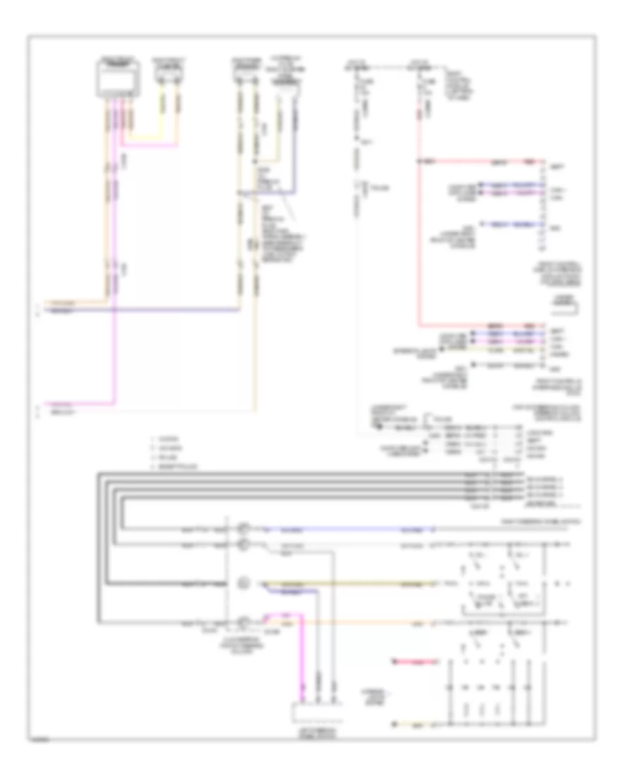
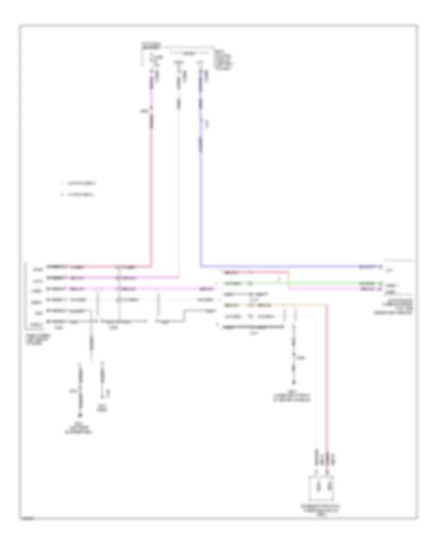
Rear Camera Wiring Diagram for Ford Explorer Sport 2014
List of elements for Rear Camera Wiring Diagram for Ford Explorer Sport 2014:
- (not used)
- Accessory protocol interface module (apim)
- Auto-dimming interior mirror (w/o lane departure warning)
- Body control module (left end of dash)
- C211
- C2280b
- C2280c
- C2280d
- C317
- C494
- C935
- Fuse 10a
- G201 (under right front of center console)
- G301 (left rear quarterpanel)
- Gnd
- Hot in run or start
- Lin 03
- Lin 1
- Micro
- Nca
- Rmp19
- S250
- S328
- S410
- Shield
- Vdn01
- Vdn03
- Video +
- Video -
- Video camera (left side of liftgate)
- Video+
- Video-
- Vmp19
- Vpwr
- W/ sync gen 2
- W/o sync gen 2