NAVIGATION
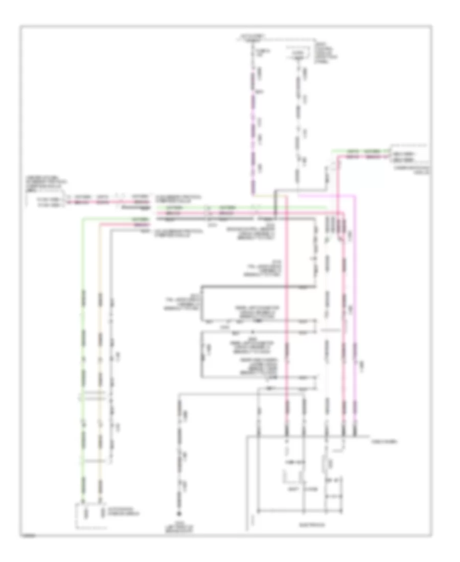
Crew Chief Wiring Diagram for Ford F-150 XLT 2013

List of elements for Crew Chief Wiring Diagram for Ford F-150 XLT 2013:
- (t-box jumper wiring harness, near breakout to c2108) s273
- (t-box jumper wiring harness, near breakout to c2108) s274
- 5vpwr
- 5vtb
- Battery junction box (bjb) (front of engine compt)
- Body control module (right kick panel)
- Boo
- Bpp
- Brake
- Brake pedal position (bpp) switch (left side of dash)
- Breakout to c110)
- C1581
- C2108
- C211
- C213
- C2280b
- C406
- Can+
- Can-
- Cgnd
- Computer data lines system
- Fuse 10a
- Fuse 30a
- Fuse 5a
- G203 (left side of dash)
- Gnd
- Gnd-a
- Gnd1
- Ground
- Hot at all times
- Hot in start or run
- Hs can +
- Hs can -
- Hsc1-a
- Hsc1-c
- Hsc2-a
- Hsc2-c
- Igrun-a
- Igrun-c
- Inline fuse (center of dash)
- Modem antenna (center of dash)
- Nca
- Pwrgnd
- Red
- Run start
- Rxd
- S272
- Tbo
- Telematics module (center of dash)
- Trailer brake control (tbc) module (left side of dash)
- Trailer tow connector (7-pin trailer tow) (rear of vehicle)
- Txd
- Vb-a
- Vb1
- Vbatt
- Vpwr
Front Camera Wiring Diagram for Ford F-150 XLT 2013
List of elements for Front Camera Wiring Diagram for Ford F-150 XLT 2013:
- (svt grille led jumper wiring harness, near breakout to front video camera) s114
- Accessory protocol interface module (apim) (center of dash)
- Auto- dimming interior mirror
- Body control module (right kick panel)
- C145
- C210
- C2280c
- C2280d
- C248
- C314
- Camera switching module
- Cbp34
- Choke
- Dmp19
- Electronics
- Front video camera
- Fuse 34 10a
- G102 (left front of engine compt)
- G202 (left side of dash)
- Gd120
- Gnd
- Hot in start or run
- Lin
- Lin 03
- Micro
- Module
- Nca
- Pwr
- R cam video +
- R cam video -
- Rear camera circuit
- Rmp19
- S117
- S119
- S122
- S124
- Shield
- Un comm
- Vbatt
- Vedio front +
- Vedio front -
- Vedio out +
- Vedio out -
- Vedio rear +
- Vedio rear -
- Video +
- Video -
- Vmp19
- W/ accessory protocol interface module
- W/o accessory protocol interface nca
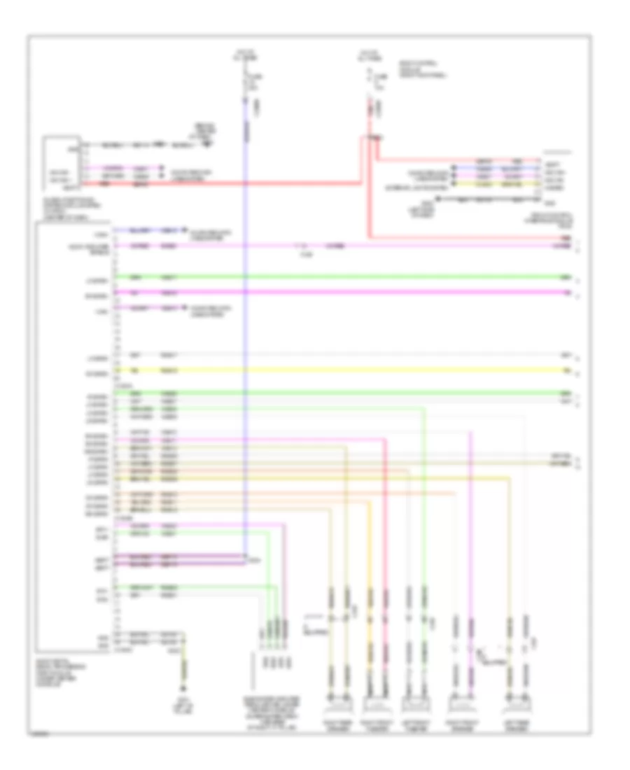
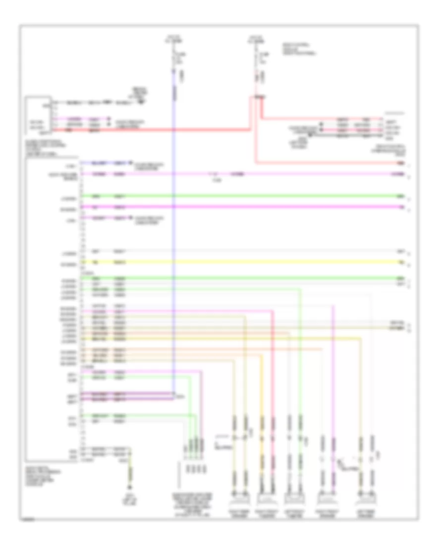
Navigation Wiring Diagram, with HMI (1 of 3) for Ford F-150 XLT 2013
List of elements for Navigation Wiring Diagram, with HMI (1 of 3) for Ford F-150 XLT 2013:
- (behind center
- Audio amplifier enable
- Audio digital signal processing (dsp) module (under center console)
- Body control module (right kick panel)
- C2280b
- C2280d
- C237
- C248
- C3154a
- C3154b
- C3154c
- C316
- C327
- Cls32
- Computer data
- Computer data lines system
- Exterior lights system
- Front control interface module (fcim)
- Fuse 10a
- Fuse 20a
- G202 (left side of dash)
- G204
- G301 (left "b" pillar)
- Gd133
- Gd148
- Global positioning system module (gpsm) (w/ sync) (center of dash)
- Gnd
- Hazard
- Hot at all times
- I can+
- I can-
- If equipped
- Ip spkr+
- Ip spkr-
- Left front tweeter
- Left rear speaker
- Lf spkr+
- Lf spkr-
- Lines system
- Lr spkr+
- Lr spkr-
- Ms can +
- Ms can -
- Ms can+
- Ms can-
- Nca
- Of dash)
- Red
- Rf spkr+
- Rf spkr-
- Right front speaker
- Right front tweeter
- Right rear speaker
- Rme01
- Rme06
- Rme07
- Rme08
- Rme09
- Rme10
- Rme11
- Rme12
- Rme17
- Rme18
- Rme22
- Rr spkr+
- Rr spkr-
- S215 gd114
- S220
- S322
- S324
- Sbp09
- Sbp19
- Sme23
- Sub+
- Subwoofer amplifier (regular cab: under center console) (super/super crew cab: base of right "c" pillar)
- Sw1+
- Sw1-
- Sw2+
- Sw2-
- Vbatt
- Vdb06
- Vdb07
- Vdb13
- Vdb14
- Vme01
- Vme06
- Vme07
- Vme08
- Vme09
- Vme10
- Vme11
- Vme12
- Vme17
- Vme18
- Vme22
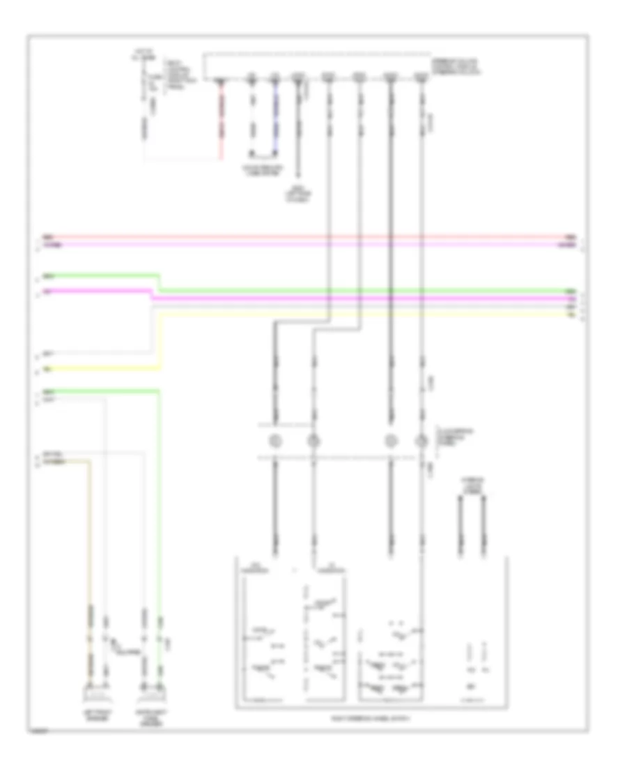
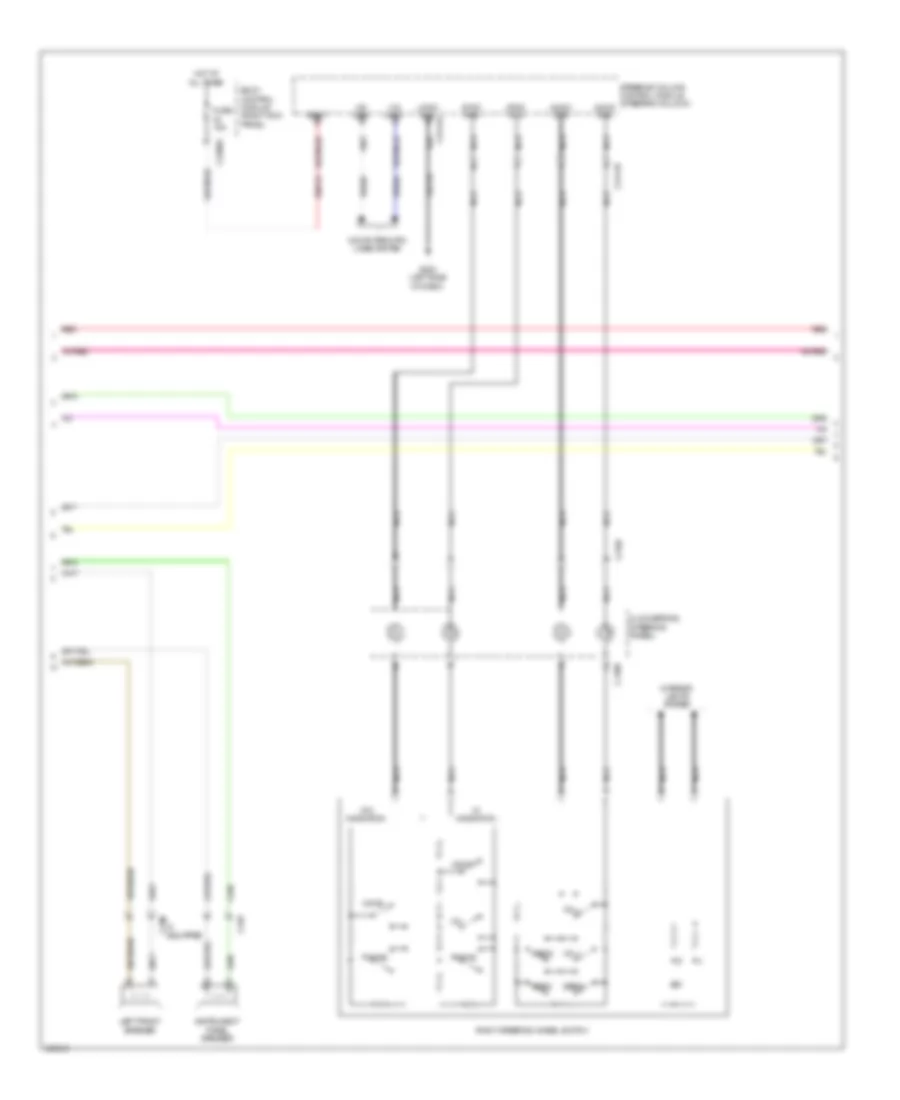
Navigation Wiring Diagram, with HMI (2 of 3) for Ford F-150 XLT 2013
List of elements for Navigation Wiring Diagram, with HMI (2 of 3) for Ford F-150 XLT 2013:
- Audio pwr
- Audio rtn
- Body control module (right kick panel)
- C218b
- C218c
- C219
- C2280a
- C2414a
- C2414d
- C248
- Clockspring (steering wheel)
- Computer data lines system
- Fuse 15a
- G202 (left side of dash)
- Gd133
- Hot at all times
- Hs can+
- Hs can-
- If equipped
- Instrument panel speaker
- Interior lights system
- Left front speaker
- Logic gnd
- Media
- Nca
- Phone
- Red
- Right steering wheel switch
- Sbp23
- Seek+
- Seek-
- Steering column control module (steering column)
- Sync pwr
- Sync rtn
- Vbatt
- Vdb04
- Vdb05
- Voice
- Vol+
- Vol-
- W/ navigation
- W/o navigation
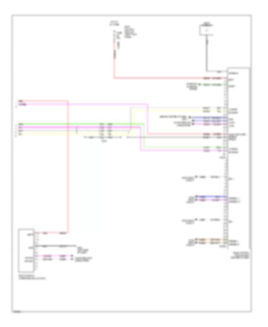
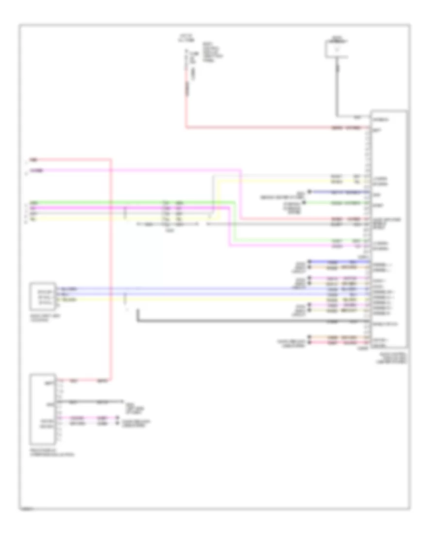
Navigation Wiring Diagram, with HMI (3 of 3) for Ford F-150 XLT 2013
List of elements for Navigation Wiring Diagram, with HMI (3 of 3) for Ford F-150 XLT 2013:
- (behind center of dash) g204
- Am/fm antenna
- Antenna
- Audio amplifier enable shield
- Audio control module (acm) (center of dash)
- Batt
- Body control module (right kick panel)
- C2280a
- C240a
- C240b
- C248
- Cdc54
- Computer data lines system
- Dme17
- Front display interface module (fdim)
- Fuse 20a
- G202 (left side of dash)
- Gd114
- Gd133
- Gnd
- Hot at all times
- I can +
- I can -
- Lf spkr+
- Lf spkr-
- Ms can+
- Ms can-
- Nca
- Red
- Rf spkr+
- Rf spkr-
- Rme17
- Rme18
- Rme52
- Rme53
- Sbp09
- Sbp29
- Sdl +
- Sdl -
- Sme23
- Start
- Starting/ charging system
- Stereo l +
- Stereo l -
- Stereo r +
- Stereo r -
- Sync radio circuit
- Vbatt
- Vdb06
- Vdb07
- Vdb13
- Vdb14
- Vme17
- Vme18
- Vme52
- Vme53
- Vme90
- Vme91
Navigation Wiring Diagram, without HMI (1 of 3) for Ford F-150 XLT 2013
List of elements for Navigation Wiring Diagram, without HMI (1 of 3) for Ford F-150 XLT 2013:
- (behind center
- Audio amplifier enable
- Audio digital signal processing (dsp) module (under center console)
- Body control module (right kick panel)
- C2280b
- C2280d
- C237
- C248
- C3154a
- C3154b
- C3154c
- C316
- C327
- Computer data
- Computer data lines system
- Front control interface module (fcim)
- Fuse 10a
- Fuse 20a
- G202 (left side of dash)
- G204
- G301 (left "b" pillar)
- Gd133
- Gd148
- Global positioning system module (gpsm) (w/ sync) (center of dash)
- Gnd
- Hot at all times
- I can +
- I can -
- If equipped
- Ip spkr+
- Ip spkr-
- Left front tweeter
- Left rear speaker
- Lf spkr+
- Lf spkr-
- Lines system
- Lr spkr+
- Lr spkr-
- Ms can +
- Ms can -
- Ms can+
- Ms can-
- Nca
- Of dash)
- Red
- Rf spkr+
- Rf spkr-
- Right front speaker
- Right front tweeter
- Right rear speaker
- Rme01
- Rme06
- Rme07
- Rme08
- Rme09
- Rme10
- Rme11
- Rme12
- Rme17
- Rme18
- Rme22
- Rr spkr+
- Rr spkr-
- S215 gd114
- S220
- S322
- S324
- Sbp09
- Sbp19
- Sme23
- Sub+
- Subwoofer amplifier (regular cab: under center console) (super/super crew cab: base of right "c" pillar)
- Sw1+
- Sw1-
- Sw2+
- Sw2-
- Vbatt
- Vdb06
- Vdb07
- Vdb13
- Vdb14
- Vme01
- Vme06
- Vme07
- Vme08
- Vme09
- Vme10
- Vme11
- Vme12
- Vme17
- Vme18
- Vme22
Navigation Wiring Diagram, without HMI (2 of 3) for Ford F-150 XLT 2013
List of elements for Navigation Wiring Diagram, without HMI (2 of 3) for Ford F-150 XLT 2013:
- Audio pwr
- Audio rtn
- Body control module (right kick panel)
- C218b
- C218c
- C219
- C2280a
- C2414a
- C2414d
- C248
- Clockspring (steering wheel)
- Computer data lines system
- Fuse 15a
- G202 (left side of dash)
- Gd133
- Hot at all times
- Hs can+
- Hs can-
- If equipped
- Instrument panel speaker
- Interior lights system
- Left front speaker
- Logic gnd
- Media
- Nca
- Phone
- Red
- Right steering wheel switch
- Sbp23
- Seek+
- Seek-
- Steering column control module (steering column)
- Sync pwr
- Sync rtn
- Vbatt
- Vdb04
- Vdb05
- Voice
- Vol+
- Vol-
- W/ navigation
- W/o navigation
Navigation Wiring Diagram, without HMI (3 of 3) for Ford F-150 XLT 2013
List of elements for Navigation Wiring Diagram, without HMI (3 of 3) for Ford F-150 XLT 2013:
- Am/fm antenna
- Antenna
- Audio amplifier enable shield
- Audio control module (acm) (center of dash)
- Audio input jack (w/o sync)
- Batt
- Body control module (right kick panel)
- C2280a
- C248
- C290a
- C290b
- Cdc54
- Computer data lines system
- Dme17
- Dme45
- Front display interface module (fdim)
- Fuse 20a
- G202 (left side of dash)
- G204 (behind center of dash)
- Gd114
- Gd133
- Gnd
- Hot at all times
- Lf spkr+
- Lf spkr-
- Mono +
- Mono -
- Ms can +
- Ms can -
- Ms can+
- Ms can-
- Nca
- Red
- Rf spkr+
- Rf spkr-
- Rme17
- Rme18
- Rme45
- Rme52
- Rme53
- Rmn14
- Sbp09
- Sbp29
- Shield or mic-
- Sme23
- St in 2l +
- St in 2l -
- St in 2r +
- Start
- Starting/ charging system
- Stereo 2l +
- Stereo 2l -
- Stereo 2r +
- Stereo l +
- Stereo l -
- Stereo r +
- Stereo r -
- Sync radio circuit
- Vbatt
- Vdb06
- Vdb07
- Vme17
- Vme18
- Vme45
- Vme46
- Vme52
- Vme53
- Vmn14
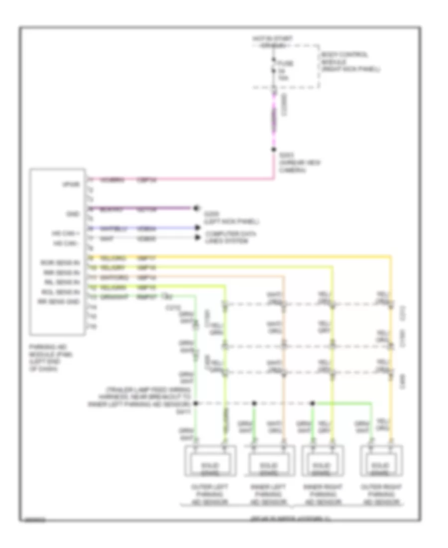
Parking Assistant Wiring Diagram for Ford F-150 XLT 2013
List of elements for Parking Assistant Wiring Diagram for Ford F-150 XLT 2013:
- (rear bumper assembly)
- (trailer lamp feed wiring harness, near breakout to inner left parking aid sensor) s411
- Body control module (right kick panel)
- C1581
- C212
- C2280d
- C406
- Cbp34
- Computer data lines system
- Fuse 10a
- G200 (left kick panel)
- Gd134
- Gnd
- Hot in start or run
- Hs can +
- Hs can -
- Inner left parking aid sensor
- Inner right parking aid sensor
- Outer left parking aid sensor
- Outer right parking aid sensor
- Parking aid module (pam) (left end of dash)
- Ril sens in
- Rir sens in
- Rmp07
- Rol sens in
- Ror sens in
- Rr sens gnd
- S203 (w/rear view camera)
- Solid state
- Vdb04
- Vdb05
- Vmp14
- Vmp15
- Vmp16
- Vmp17
- Vpwr
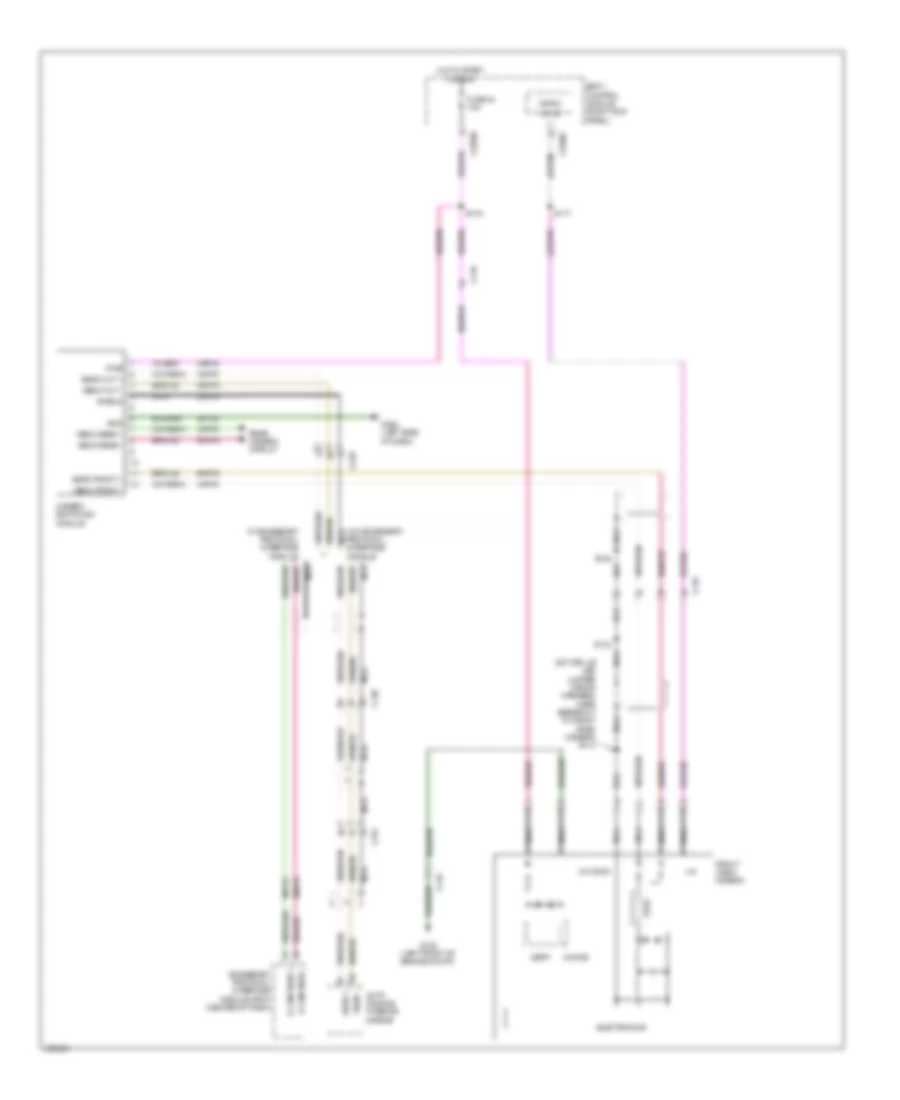
Rear Camera Wiring Diagram for Ford F-150 XLT 2013
List of elements for Rear Camera Wiring Diagram for Ford F-150 XLT 2013:
- (center of dash) accessory protocol interface module (apim)
- (rear lamp connector wiring harness, in breakout to c405) s402
- (rear video camera jumper wiring assembly, near breakout to c4000) s415
- Auto-dimming interior mirror
- Body control module (right kick panel)
- C134
- C1581
- C210
- C212
- C2280c
- C2280d
- C248
- C314
- C4000
- C405
- Camera switching module
- Choke
- Electronics
- Fuse 34 10a
- G102 (left front of engine compt)
- Hot in start or run
- Lin 03
- Micro
- Nca
- R cam video +
- R cam video -
- Rmp19
- S132 (engine control sensor wiring harness, in breakout to c1581)
- S145 (tail lamps wiring harness, in breakout to c1581)
- S203
- S406 (rear lamp connector wiring harness, in breakout to c4000)
- S413 (tail lamps wiring harness, in breakout to c405)
- S414
- Vbatt
- Vedio rear +
- Vedio rear -
- Video +
- Video -
- Video camera
- Vmp19
- W/ accessory protocol interface module
- W/o accessory protocol interface module