NAVIGATION
Mobile Telematic System Wiring Diagram for Hyundai Azera 2012

List of elements for Mobile Telematic System Wiring Diagram for Hyundai Azera 2012:
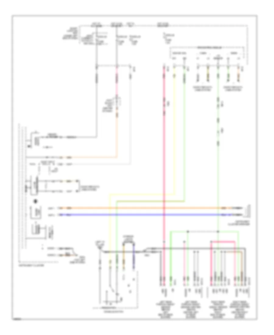
Navigation Wiring Diagram (1 of 4) for Hyundai Azera 2012
List of elements for Navigation Wiring Diagram (1 of 4) for Hyundai Azera 2012:
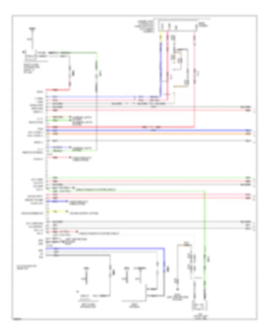
Navigation Wiring Diagram (2 of 4) for Hyundai Azera 2012
List of elements for Navigation Wiring Diagram (2 of 4) for Hyundai Azera 2012:
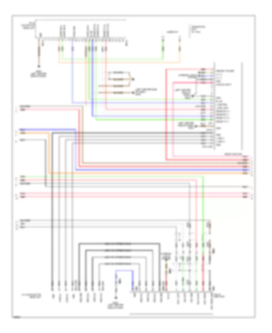
Navigation Wiring Diagram (3 of 4) for Hyundai Azera 2012
List of elements for Navigation Wiring Diagram (3 of 4) for Hyundai Azera 2012:
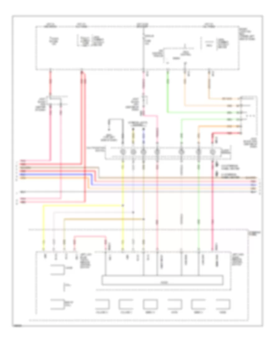
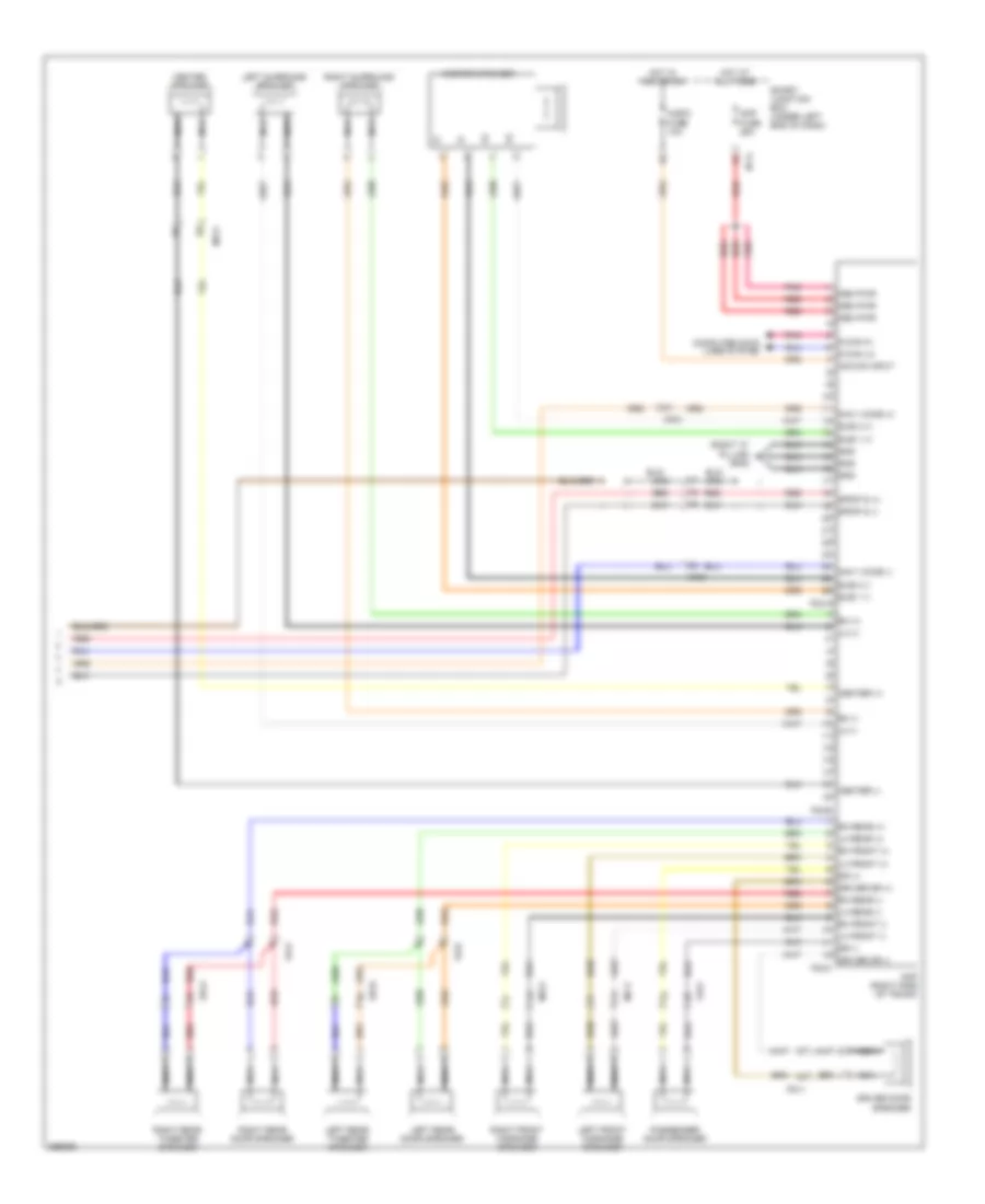
Navigation Wiring Diagram (4 of 4) for Hyundai Azera 2012
List of elements for Navigation Wiring Diagram (4 of 4) for Hyundai Azera 2012:
Parking Assistant Wiring Diagram for Hyundai Azera 2012
List of elements for Parking Assistant Wiring Diagram for Hyundai Azera 2012: