NAVIGATION
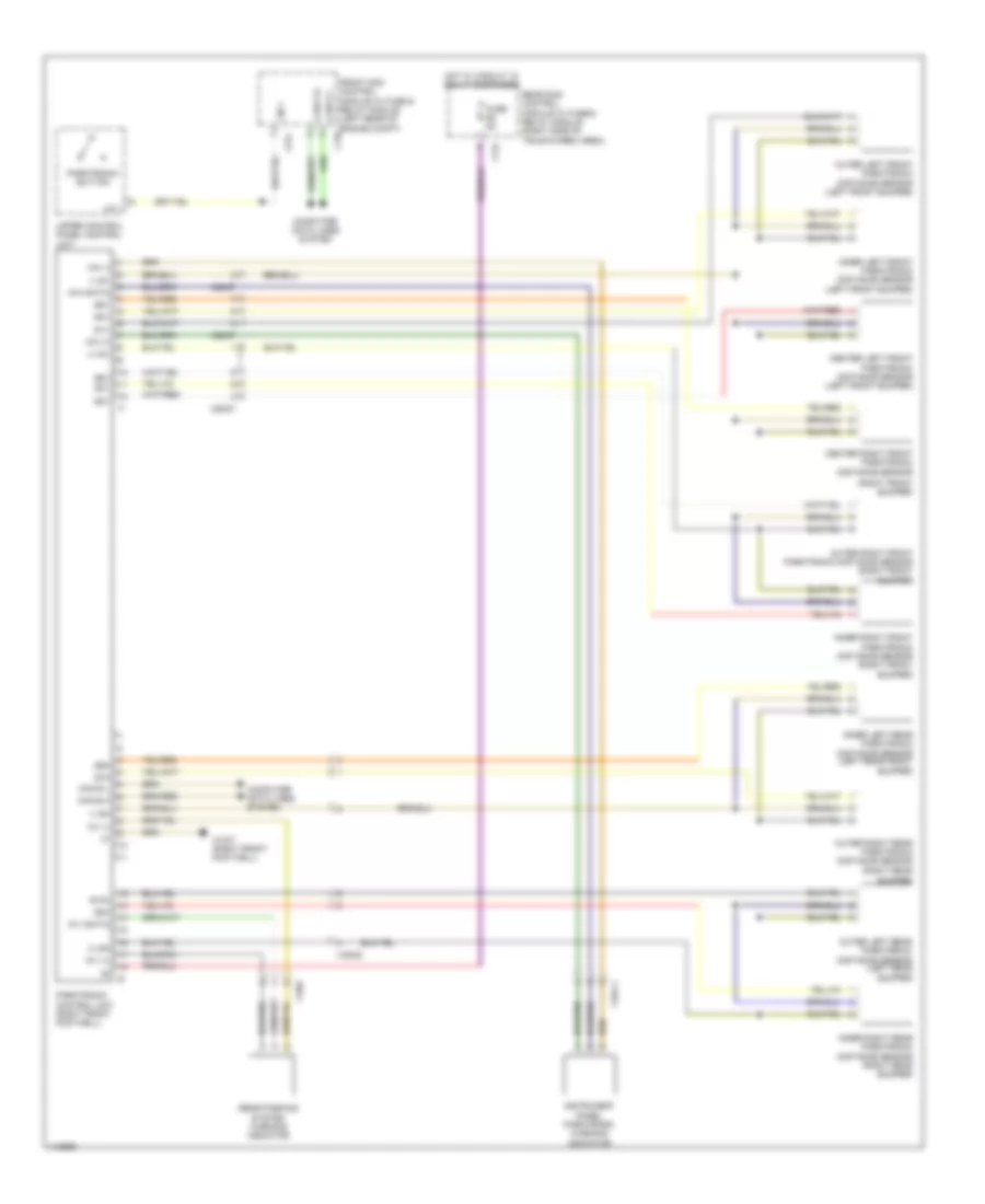
Blind Spot Information System Wiring Diagram for Mercedes-Benz C350 2014

List of elements for Blind Spot Information System Wiring Diagram for Mercedes-Benz C350 2014:
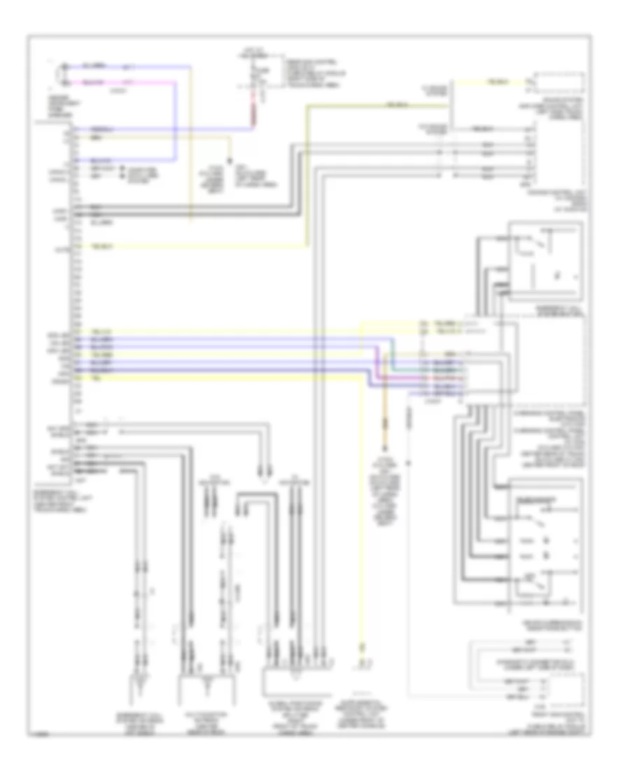
Emergency Call Wiring Diagram for Mercedes-Benz C350 2014
List of elements for Emergency Call Wiring Diagram for Mercedes-Benz C350 2014:
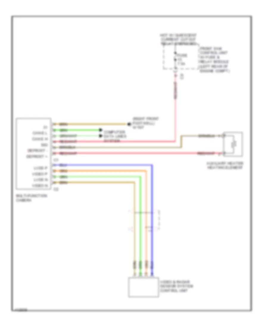
Multifunction Camera Wiring Diagram for Mercedes-Benz C350 2014
List of elements for Multifunction Camera Wiring Diagram for Mercedes-Benz C350 2014:
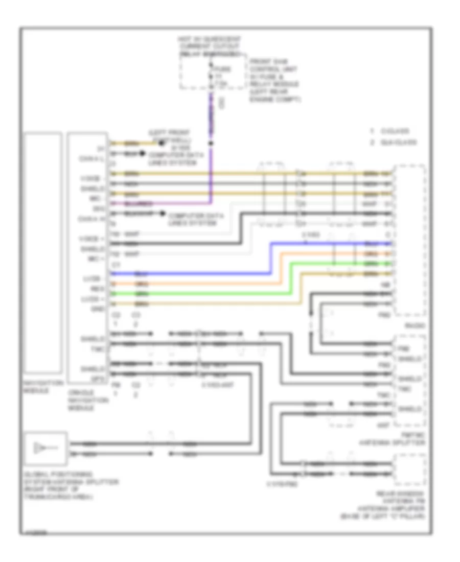
Navigation Wiring Diagram for Mercedes-Benz C350 2014
List of elements for Navigation Wiring Diagram for Mercedes-Benz C350 2014:
Parktronic Wiring Diagram for Mercedes-Benz C350 2014
List of elements for Parktronic Wiring Diagram for Mercedes-Benz C350 2014: