NAVIGATION
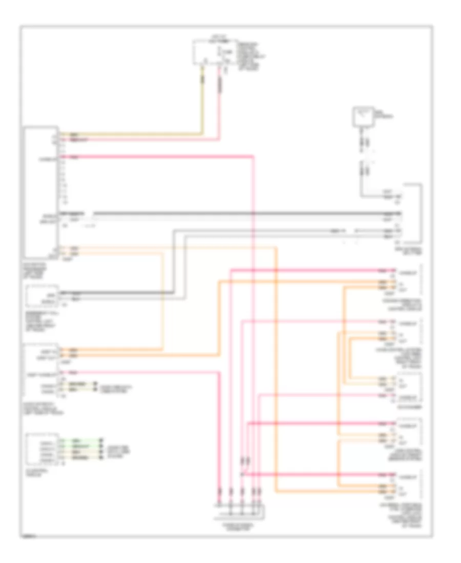
COMAND Actuation Wiring Diagram for Mercedes-Benz CLS550 2008

List of elements for COMAND Actuation Wiring Diagram for Mercedes-Benz CLS550 2008:
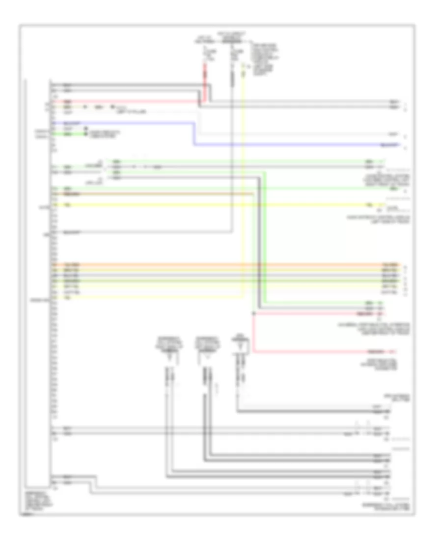
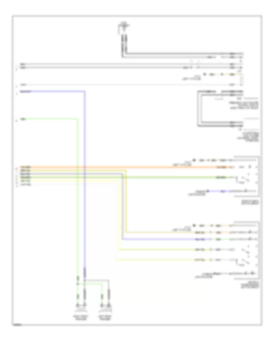
Navigation Wiring Diagram for Mercedes-Benz CLS550 2008
List of elements for Navigation Wiring Diagram for Mercedes-Benz CLS550 2008:
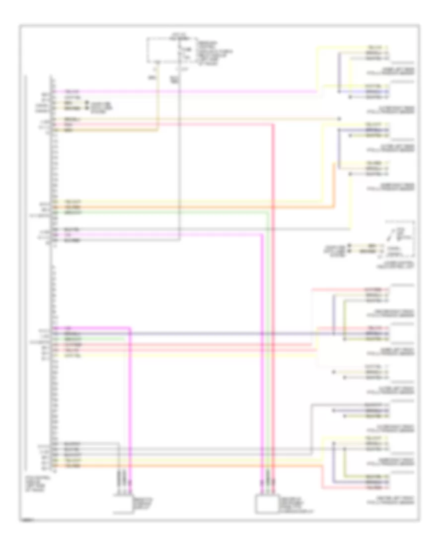
Parktronic Wiring Diagram for Mercedes-Benz CLS550 2008
List of elements for Parktronic Wiring Diagram for Mercedes-Benz CLS550 2008:
Tele Aid Wiring Diagram (1 of 2) for Mercedes-Benz CLS550 2008
List of elements for Tele Aid Wiring Diagram (1 of 2) for Mercedes-Benz CLS550 2008:
Tele Aid Wiring Diagram (2 of 2) for Mercedes-Benz CLS550 2008
List of elements for Tele Aid Wiring Diagram (2 of 2) for Mercedes-Benz CLS550 2008:
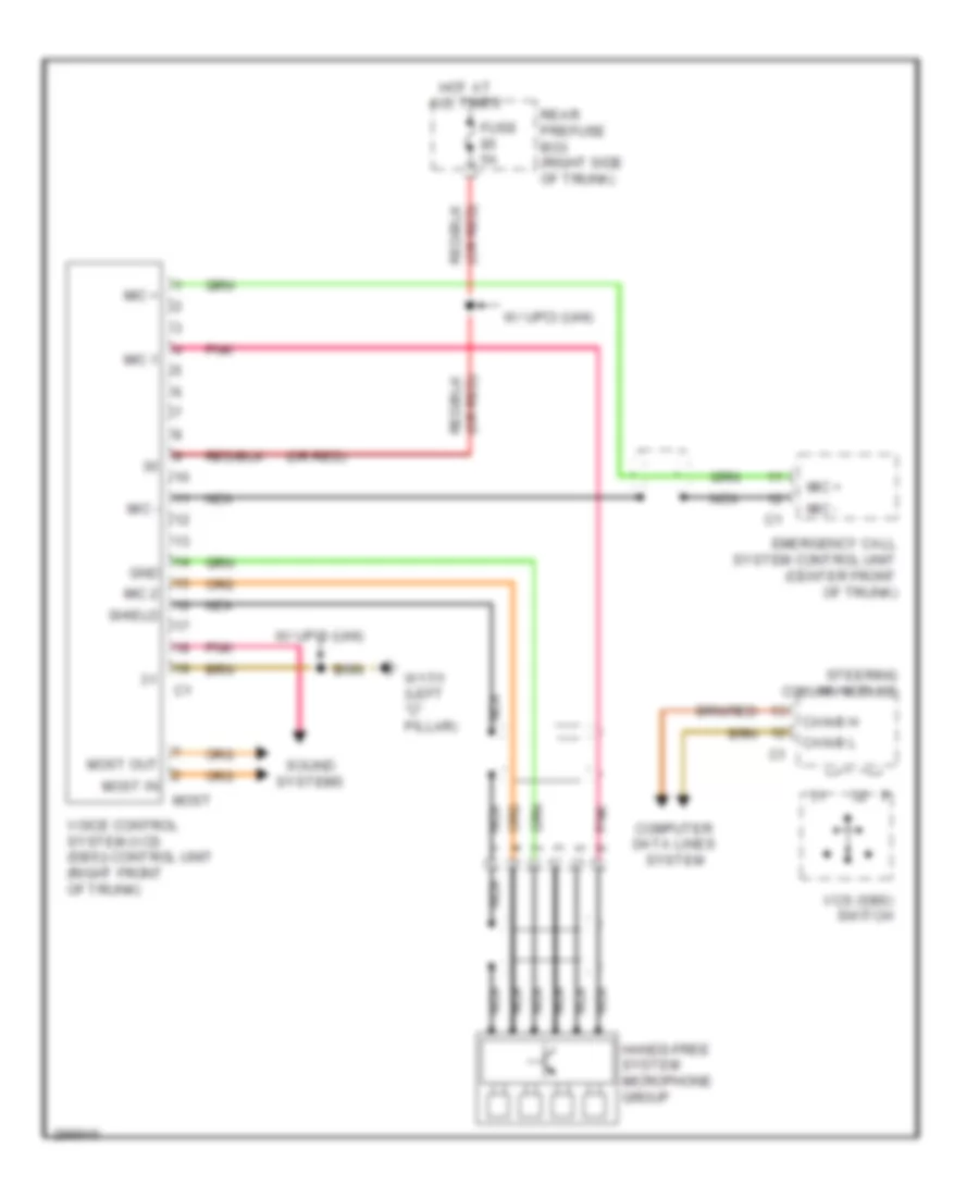
Voice Activation Wiring Diagram for Mercedes-Benz CLS550 2008
List of elements for Voice Activation Wiring Diagram for Mercedes-Benz CLS550 2008: