NAVIGATION
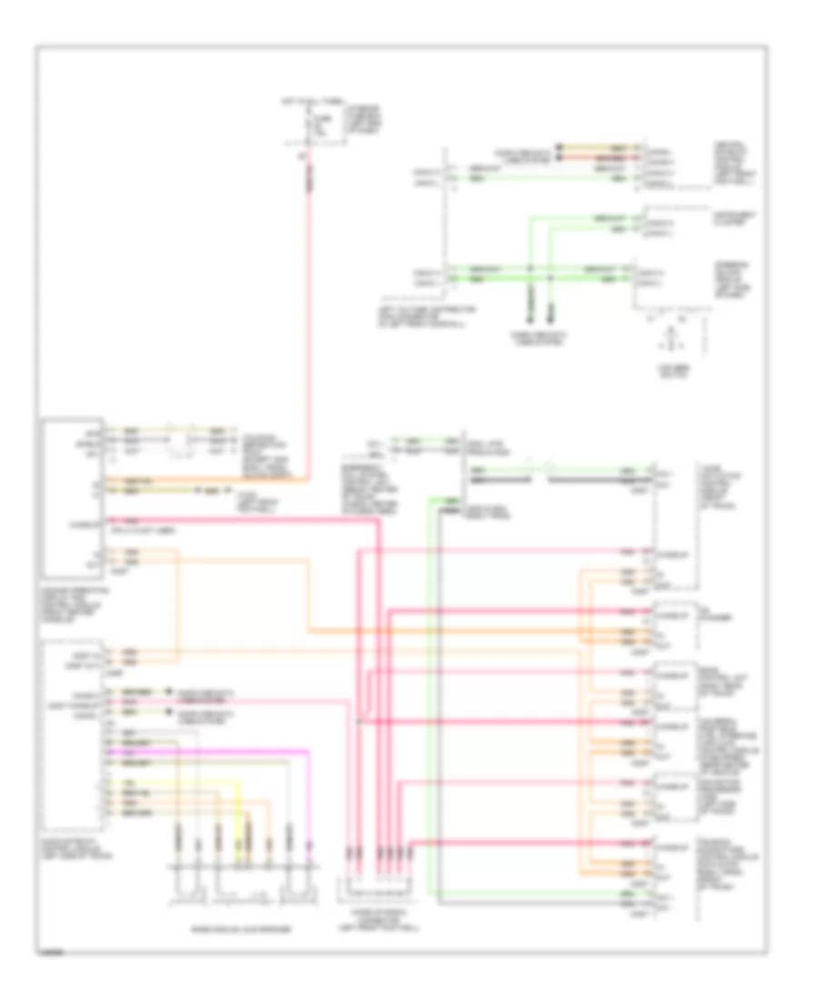
Auto Pilot System Wiring Diagram for Mercedes-Benz E320 2005

List of elements for Auto Pilot System Wiring Diagram for Mercedes-Benz E320 2005:
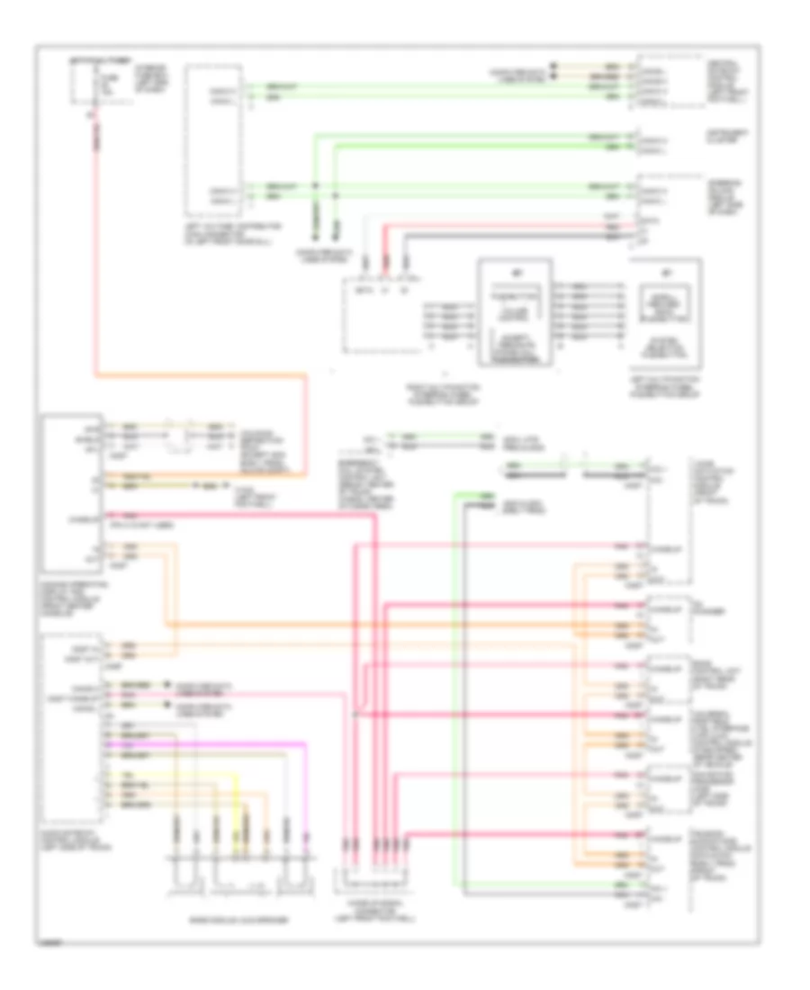
COMAND Actuation Wiring Diagram for Mercedes-Benz E320 2005
List of elements for COMAND Actuation Wiring Diagram for Mercedes-Benz E320 2005:
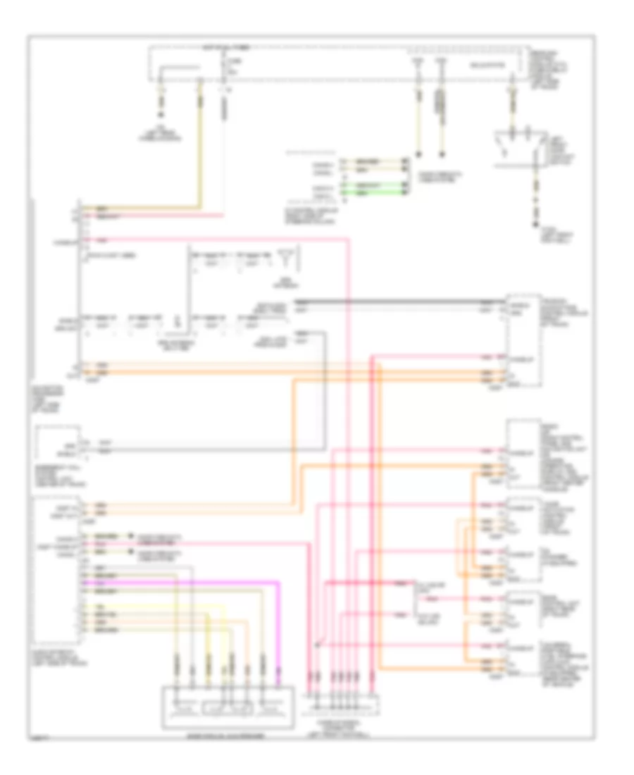
Navigation Wiring Diagram for Mercedes-Benz E320 2005
List of elements for Navigation Wiring Diagram for Mercedes-Benz E320 2005:
Parktronic Wiring Diagram for Mercedes-Benz E320 2005
List of elements for Parktronic Wiring Diagram for Mercedes-Benz E320 2005:
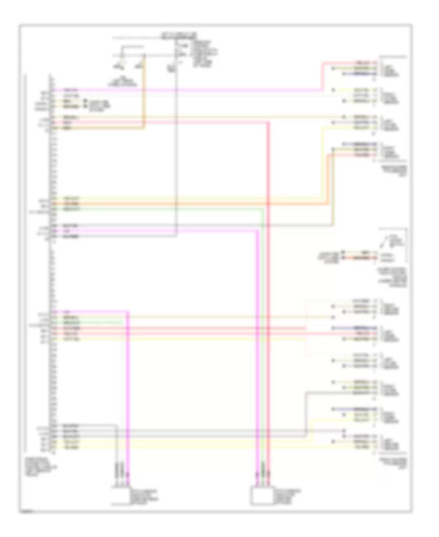
Voice Activation Wiring Diagram for Mercedes-Benz E320 2005
List of elements for Voice Activation Wiring Diagram for Mercedes-Benz E320 2005: