NAVIGATION
All Around Vision Camera Wiring Diagram for Mercedes-Benz S550 4Matic 2014

List of elements for All Around Vision Camera Wiring Diagram for Mercedes-Benz S550 4Matic 2014:
Blind Spot Information System Wiring Diagram for Mercedes-Benz S550 4Matic 2014
List of elements for Blind Spot Information System Wiring Diagram for Mercedes-Benz S550 4Matic 2014:
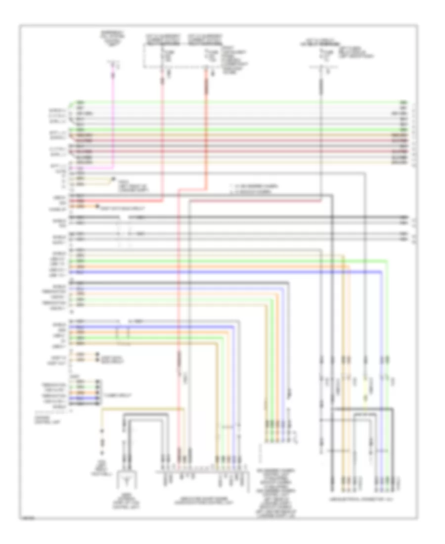
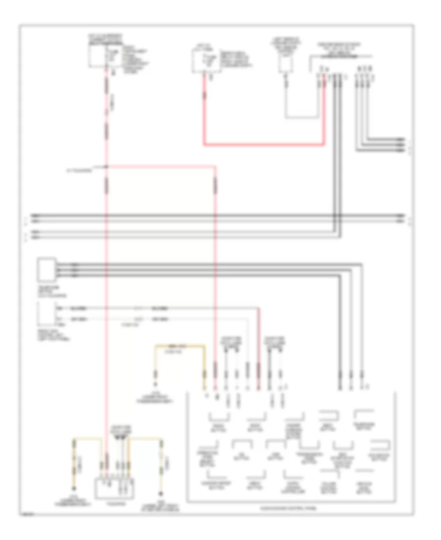
COMAND Actuation Wiring Diagram (1 of 6) for Mercedes-Benz S550 4Matic 2014
List of elements for COMAND Actuation Wiring Diagram (1 of 6) for Mercedes-Benz S550 4Matic 2014:
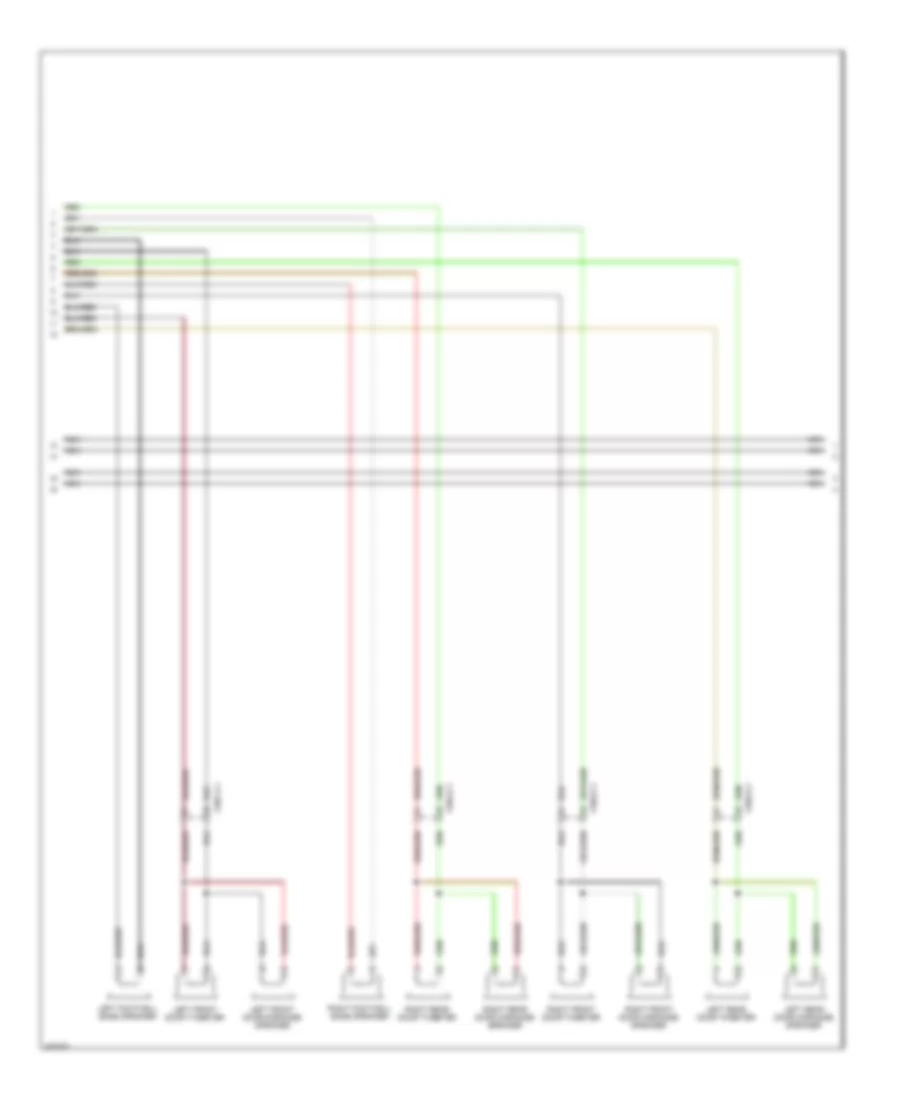
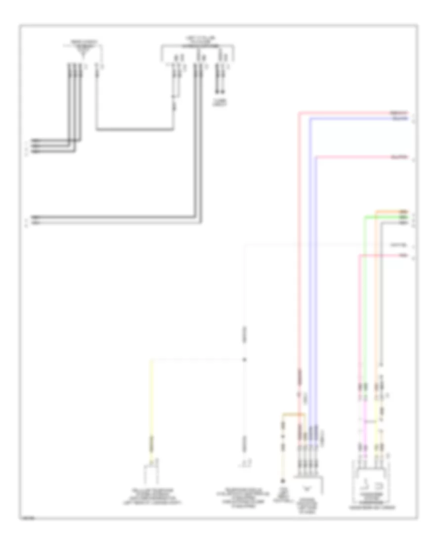
COMAND Actuation Wiring Diagram (2 of 6) for Mercedes-Benz S550 4Matic 2014
List of elements for COMAND Actuation Wiring Diagram (2 of 6) for Mercedes-Benz S550 4Matic 2014:
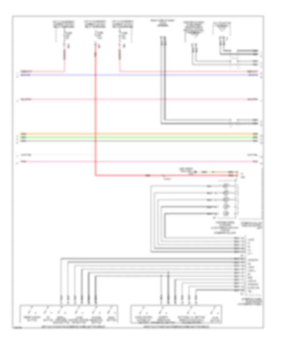
COMAND Actuation Wiring Diagram (3 of 6) for Mercedes-Benz S550 4Matic 2014
List of elements for COMAND Actuation Wiring Diagram (3 of 6) for Mercedes-Benz S550 4Matic 2014:
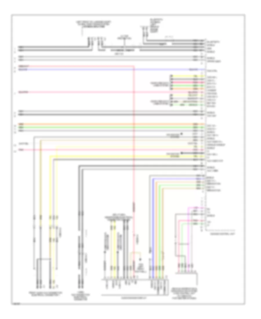
COMAND Actuation Wiring Diagram (4 of 6) for Mercedes-Benz S550 4Matic 2014
List of elements for COMAND Actuation Wiring Diagram (4 of 6) for Mercedes-Benz S550 4Matic 2014:
COMAND Actuation Wiring Diagram (5 of 6) for Mercedes-Benz S550 4Matic 2014
List of elements for COMAND Actuation Wiring Diagram (5 of 6) for Mercedes-Benz S550 4Matic 2014:
COMAND Actuation Wiring Diagram (6 of 6) for Mercedes-Benz S550 4Matic 2014
List of elements for COMAND Actuation Wiring Diagram (6 of 6) for Mercedes-Benz S550 4Matic 2014:
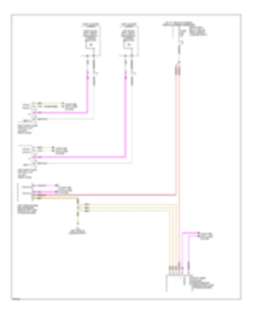
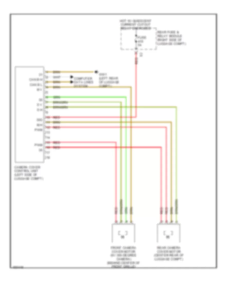
Camera Cover Control Wiring Diagram for Mercedes-Benz S550 4Matic 2014
List of elements for Camera Cover Control Wiring Diagram for Mercedes-Benz S550 4Matic 2014:
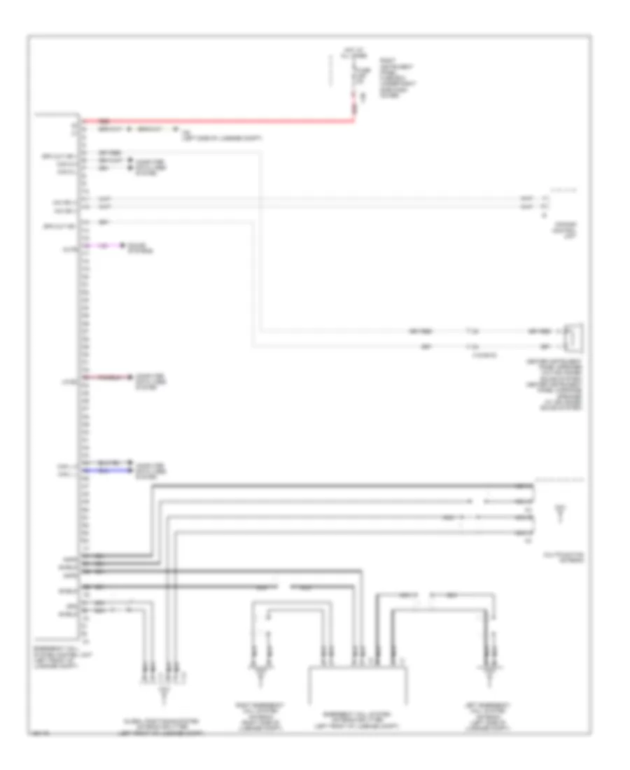
Emergency Call Wiring Diagram for Mercedes-Benz S550 4Matic 2014
List of elements for Emergency Call Wiring Diagram for Mercedes-Benz S550 4Matic 2014:
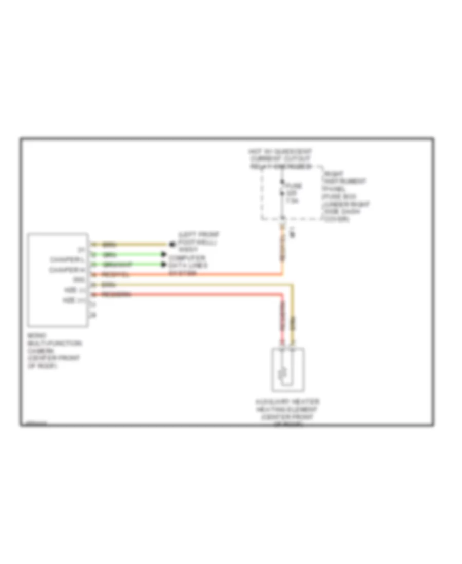
Multifunction Camera Wiring Diagram for Mercedes-Benz S550 4Matic 2014
List of elements for Multifunction Camera Wiring Diagram for Mercedes-Benz S550 4Matic 2014:
Parktronic Wiring Diagram for Mercedes-Benz S550 4Matic 2014
List of elements for Parktronic Wiring Diagram for Mercedes-Benz S550 4Matic 2014:
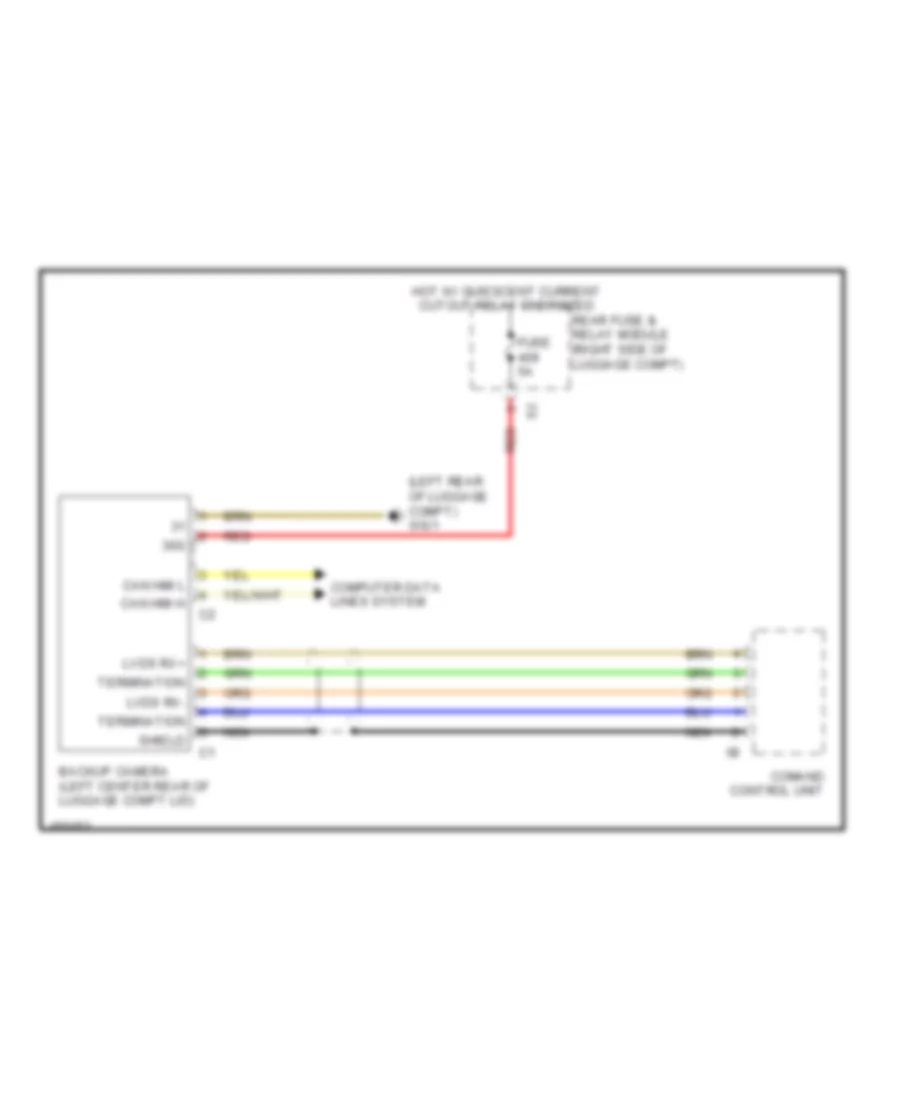
Rear Camera Wiring Diagram for Mercedes-Benz S550 4Matic 2014
List of elements for Rear Camera Wiring Diagram for Mercedes-Benz S550 4Matic 2014:
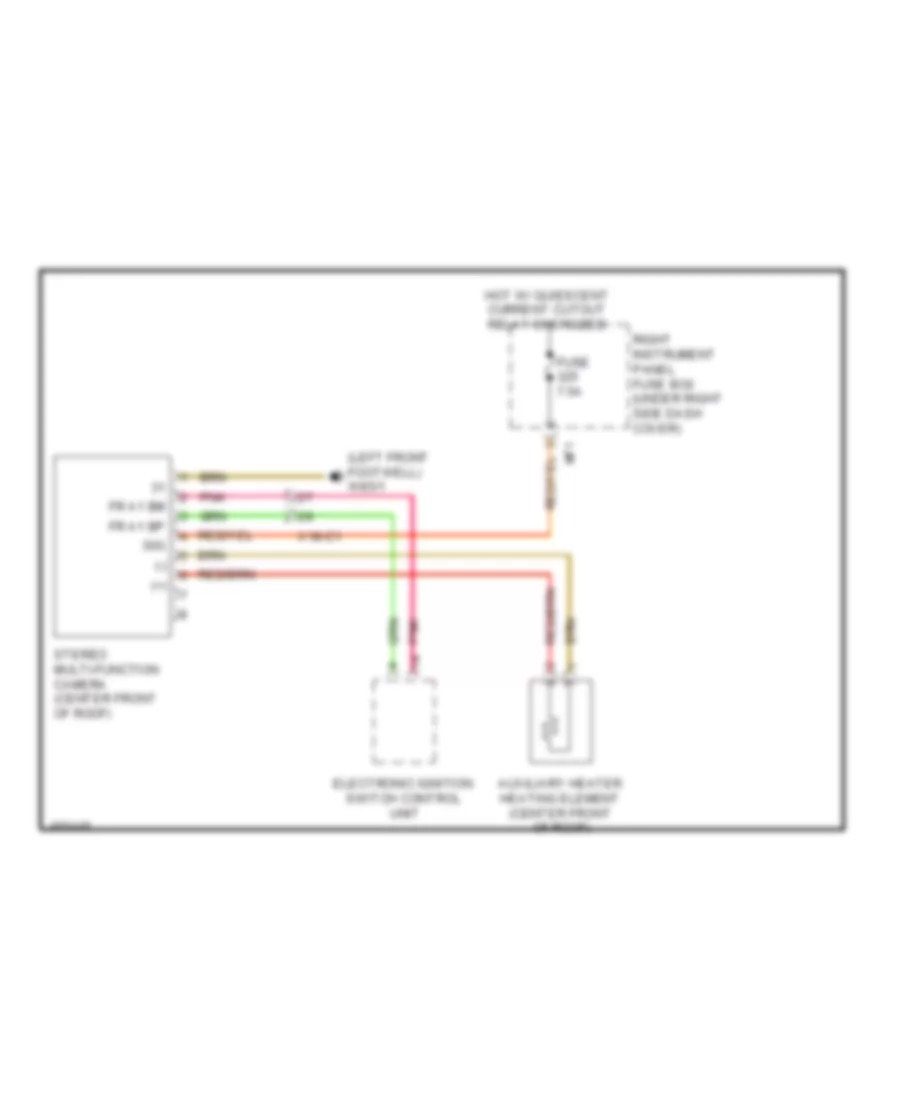
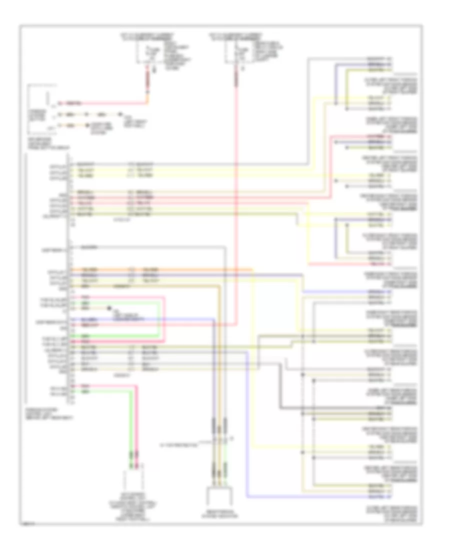
Stereo Multifunction Camera Wiring Diagram for Mercedes-Benz S550 4Matic 2014
List of elements for Stereo Multifunction Camera Wiring Diagram for Mercedes-Benz S550 4Matic 2014: