NAVIGATION
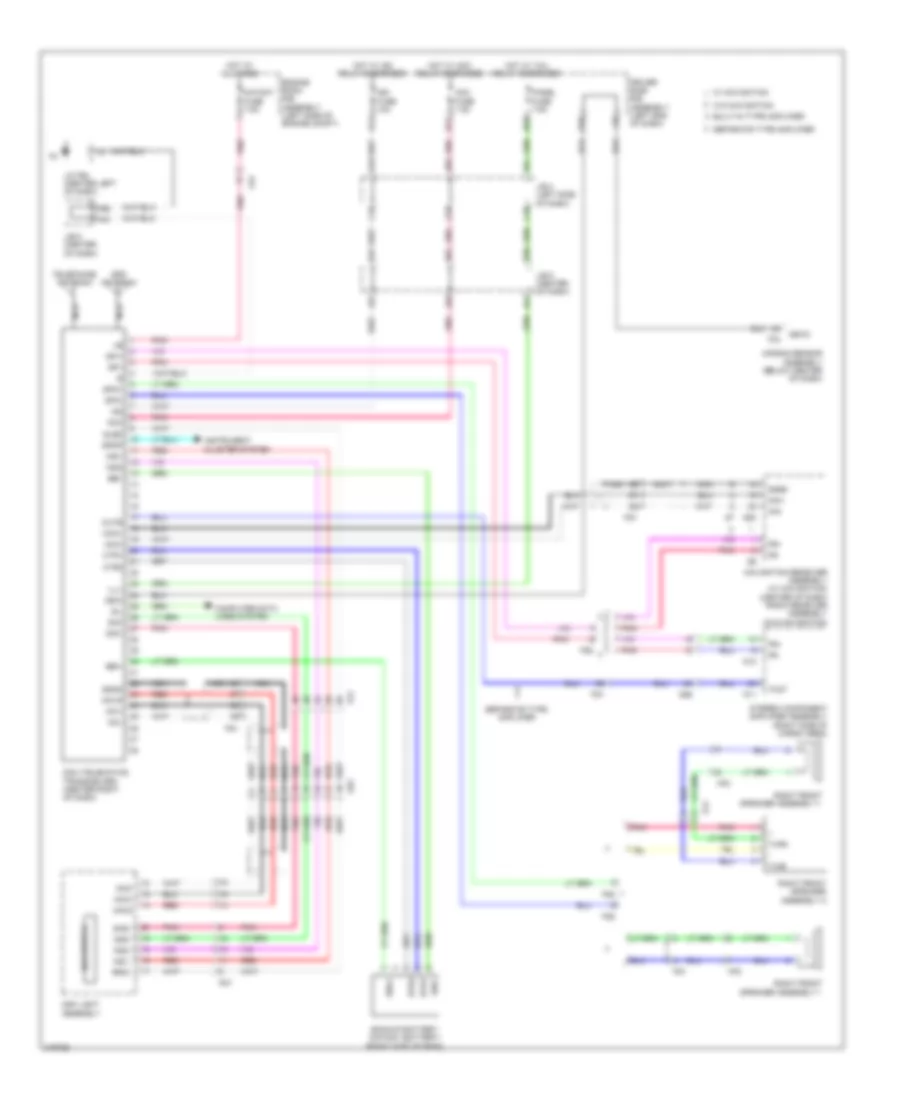
Navigation Wiring Diagram (1 of 3) for Toyota 4Runner SR5 2011

List of elements for Navigation Wiring Diagram (1 of 3) for Toyota 4Runner SR5 2011:
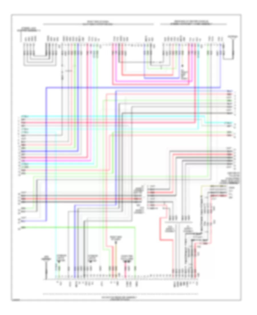
Navigation Wiring Diagram (2 of 3) for Toyota 4Runner SR5 2011
List of elements for Navigation Wiring Diagram (2 of 3) for Toyota 4Runner SR5 2011:
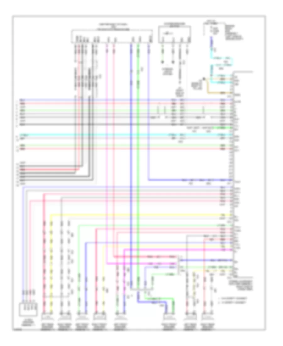
Navigation Wiring Diagram (3 of 3) for Toyota 4Runner SR5 2011
List of elements for Navigation Wiring Diagram (3 of 3) for Toyota 4Runner SR5 2011:
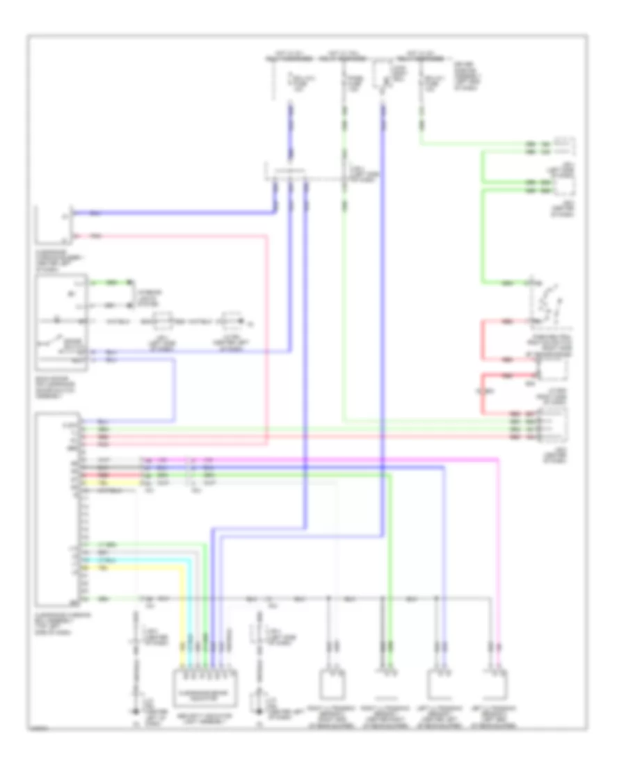
Parking Assistant Wiring Diagram for Toyota 4Runner SR5 2011
List of elements for Parking Assistant Wiring Diagram for Toyota 4Runner SR5 2011:
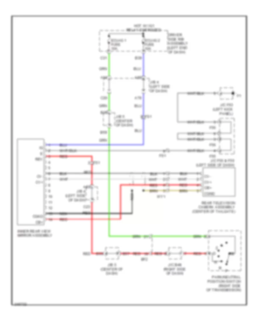
Rear View Camera Wiring Diagram for Toyota 4Runner SR5 2011
List of elements for Rear View Camera Wiring Diagram for Toyota 4Runner SR5 2011:
Telematics Wiring Diagram for Toyota 4Runner SR5 2011
List of elements for Telematics Wiring Diagram for Toyota 4Runner SR5 2011: