NAVIGATION
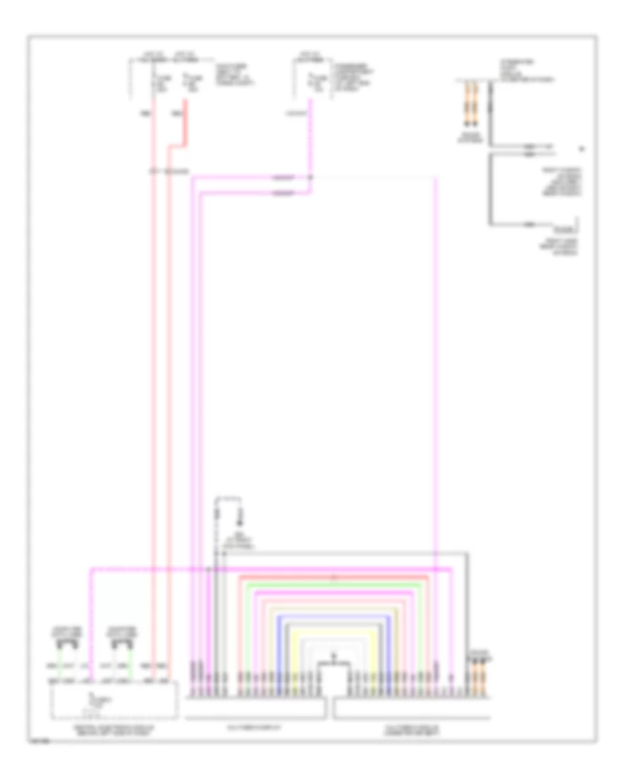
Blind Spot Information System Wiring Diagram for Volvo XC90 2013

List of elements for Blind Spot Information System Wiring Diagram for Volvo XC90 2013:
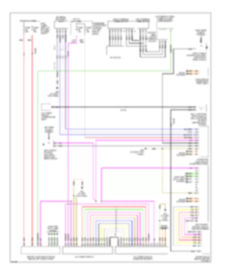
Infotainment Wiring Diagram for Volvo XC90 2013
List of elements for Infotainment Wiring Diagram for Volvo XC90 2013:
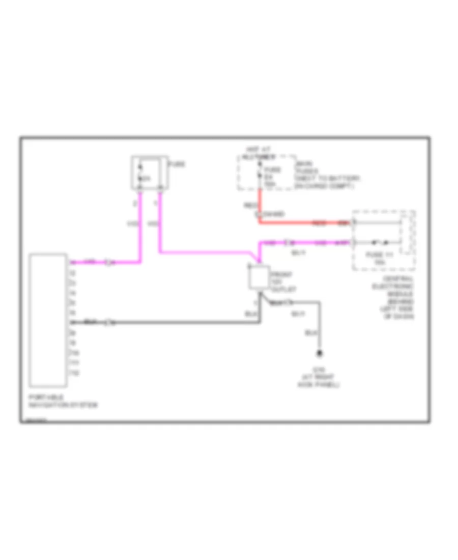
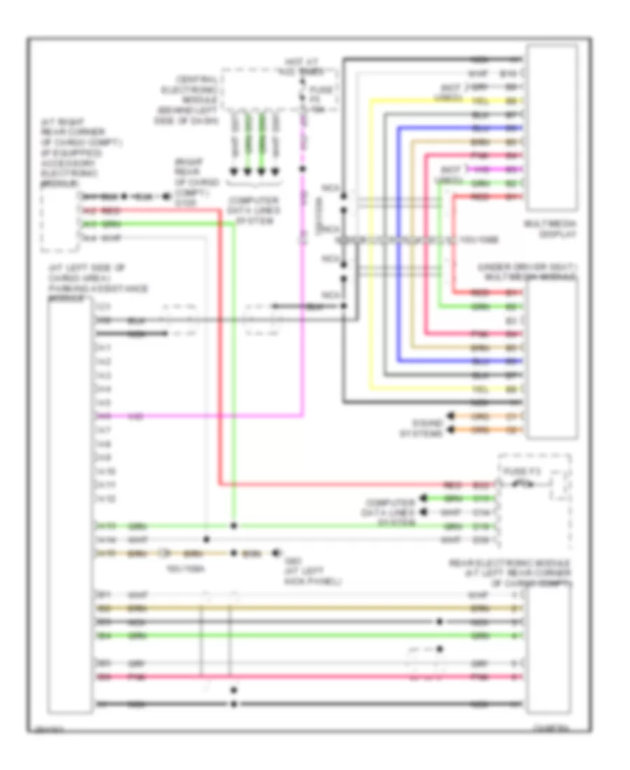
Navigation Wiring Diagram for Volvo XC90 2013
List of elements for Navigation Wiring Diagram for Volvo XC90 2013:
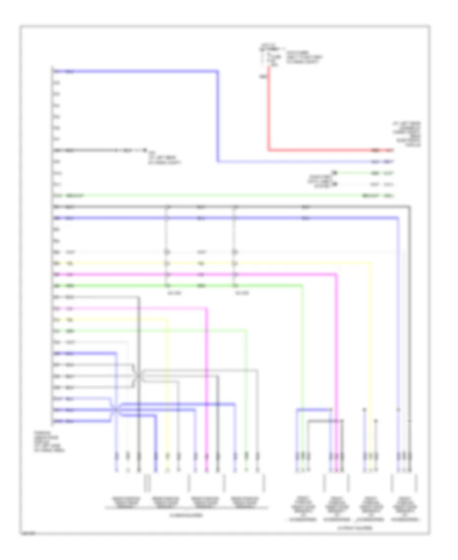
Parking Assistant Wiring Diagram for Volvo XC90 2013
List of elements for Parking Assistant Wiring Diagram for Volvo XC90 2013:
Rear Camera Wiring Diagram for Volvo XC90 2013
List of elements for Rear Camera Wiring Diagram for Volvo XC90 2013:
Road Traffic Information Wiring Diagram for Volvo XC90 2013
List of elements for Road Traffic Information Wiring Diagram for Volvo XC90 2013: