ANTI-LOCK BRAKES
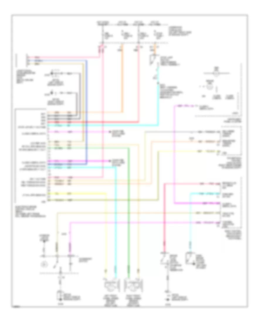
Anti-lock Brakes Wiring Diagram for Isuzu i-370 LS 2007
List of elements for Anti-lock Brakes Wiring Diagram for Isuzu i-370 LS 2007:
- 2wd
- A17
- A26
- A31
- A39
- A45
- Abs 1 fuse 45 30a
- Abs 2 fuse 44 40a
- Abs fuse 16 10a
- Abs ind
- Accessory switch
- B c5
- Bat
- Body control module (bcm) (behind right kick panel)
- Brake fluid level switch (on brake fluid reservoir)
- Brake fluid lvl sens sig
- Brake ind
- C2 b
- C2 h
- Class 2 (ebcm)
- Class 2 serial data
- Computer data lines system
- Del torque sig (2wd)
- Delivered torque signal
- E11 c7
- Electronic brake control module (ebcm) (on inner left frame rail, beside transmission)
- G105
- G106
- Gnd
- Hot at all times
- Hot in run or start
- Ign
- Ign 1 voltage
- Instrument panel cluster
- Interior lights system
- Left front wheel speed sensor (on left front hub)
- Lf spd sens sply volt
- Lf whl spd sens sig
- Lng rate sig (4wd)
- Logic
- Longitudinal accelerometer sensor (4wd) (below driver seat)
- Low ref (4wd
- Park brake switch (lower left end of dash)
- Park brk sw sig
- Pnk
- Powertrain control module (pcm) (right rear corner of engine compt)
- Red
- Req torque sig (2wd)
- Requested torque signal
- Rf spd sens sply volt
- Rf whl spd sens sig
- Right front wheel speed sensor (on right front hub)
- S100 (body harness, 14.5 cm from accelerator pedal position switch breakout)
- Sp105 (left side of engine compt)
- Sp106 (right side of engine compt)
- Stop fuse 1 20a
- Stop lamp switch (above brake pedal assembly)
- Stop lmp sply voltage
- Tan
- Tcs req indicator ctrl
- Trac ctrl sw sig
- Underhood fuse block (on left front side of engine compt)
- Vss
 Čeština
 Dansk
Dansk Deutsch
 Ελληνικά
 English
 English
 Español
 Suomi
Suomi Français
 Français
 עברית
עברית Hrvatski
 Magyar
 Italiano
 日本語
日本語 한국어
한국어 Polski
 Português
 Português
 Română
 Русский
 Slovenčina
 Slovenščina
 Svenska
 Türkçe
 中文 (中国)
 Nederlands