ENGINE PERFORMANCE
3.7L
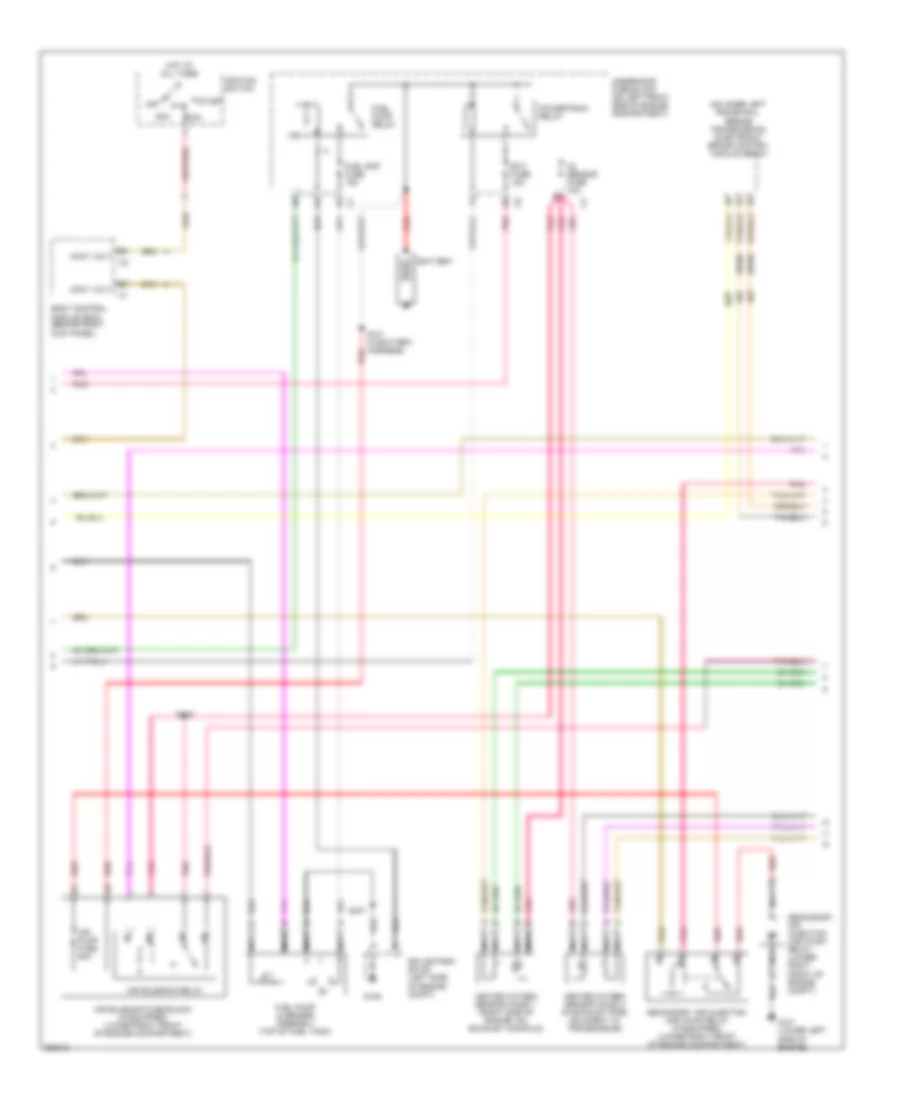
3.7L, Engine Performance Wiring Diagram (1 of 5) for Isuzu i-370 LS 2007
 https://portal-diagnostov.com/license.html
Automotive Electricians Portal FZCO
Automotive Electricians Portal FZCO
https://portal-diagnostov.com/license.html
https://portal-diagnostov.com/license.html
Automotive Electricians Portal FZCO
Automotive Electricians Portal FZCO
List of elements for 3.7L, Engine Performance Wiring Diagram (1 of 5) for Isuzu i-370 LS 2007:
- (body harness, 14.5 cm from accelerator pedal position switch breakout) s100
- (chassis harness, 39 cm before fuel pump & sender assembly)
- (part of transfer case) (4wd) transfer case shift control module
- 4wd lo sw
- A/c comp rly
- A/c press
- A/c refrigerant pressure sensor (right rear of engine compt)
- Accelerator pedal position (app) sensor (on accelerator bracket)
- Accy volt
- Air conditioning system
- Air pump rly
- App 1
- App 1 +5v ref
- App 1 low ref
- App 2
- App 2 +5v ref
- App 2 low ref
- App sens 1
- App sens 2
- Arp +5v ref
- Arp low ref
- Batt pos volt
- Can vent fuse 10a
- Class 2 data
- Cluster fuse 10a
- Computer data lines system
- Cpp sw sig
- Cruise control system
- Cruise ctrls
- Diag enable
- E11
- Evap vent sol
- Evaporative emission (evap) canister vent solenoid (on side of evap canister, above spare tire)
- Exterior lights system
- Ftp +5v ref
- Fuel lvl sens
- Fuel pump rly
- Fuel tank press
- Fuel tank pressure (ftp) sensor (at top left rear of fuel tank)
- Hot at all times
- Hot in run & start
- Ignition 1 volt
- Instrument panel cluster
- Iss sig
- Low ref
- Malfunction indicator lamp (mil)
- Mil ctrl
- Pcm 1 fuse 10a
- Pcm b fuse 10a
- Pnk
- Pnp/clutch sig
- Powertrain control module (pcm) (right rear corner of engine compt)
- S310
- Starter rly
- Starting/ charging system
- Stop fuse 20a
- Stop lamp
- Stop lamp switch (above brake pedal assembly)
- Tan
- Tcc brk sw
- Underhood fuse block (on left front side of engine compartment)
- Vehicle spd sig
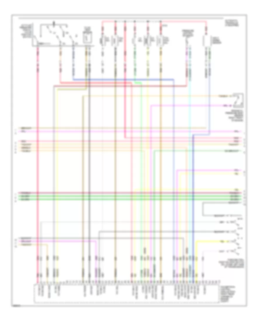
3.7L, Engine Performance Wiring Diagram (2 of 5) for Isuzu i-370 LS 2007
List of elements for 3.7L, Engine Performance Wiring Diagram (2 of 5) for Isuzu i-370 LS 2007:
- (2wd)
- (on inner left frame rail, beside transmission) electronic brake control module (ebcm)
- Acc
- Accy volt
- Air pump fuse 50a
- Air solenoid fuse block (if equipped) (lower right front of engine compartment)
- Air solenoid relay
- Battery
- Body control module (bcm) (behind right kick panel)
- Etc fuse 15a
- Fuel pmp fuse 15a
- Fuel pump & sender assembly (top of fuel tank)
- Fuel pump relay
- G101 (lower left side of engine)
- G105
- Heated oxygen sensor (ho2s) 1 (right side of engine, on exhaust manifold)
- Heated oxygen sensor (ho2s) 2 (in exhaust pipe, adjacent to transmission)
- Hot at all times
- Ignition switch
- Nca
- O2 sensor fuse 10a
- Off
- Pnk
- Powertrain relay
- Red
- Run
- S101 (in battery harness)
- S105
- S401
- Secondary air injection (air) pump relay (if equipped) (lower right front of engine compartment)
- Secondary air injection (air) pump relay (lower right front of engine compt)
- Splice pack sp105 (left side of engine compt)
- Start
- Underhood fuse block (on left front side of engine compartment)
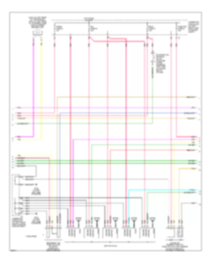
3.7L, Engine Performance Wiring Diagram (3 of 5) for Isuzu i-370 LS 2007
List of elements for 3.7L, Engine Performance Wiring Diagram (3 of 5) for Isuzu i-370 LS 2007:
- (2wd)
- 1-2 sol
- 2-3 sol
- 3-2 sol
- A/t fluid pressure manual valve position switch
- Air inj reac
- Automatic transaxle (if equpped)
- Del torque
- Engine oil pressure (eop) sensor (right front of engine)
- Evap purge
- Fluid temp sensor
- Ho2s 2 hi
- Ho2s 2 htr
- Ho2s 2 low
- Input speed sensor
- Iss low ref
- Low oil sw
- Low ref
- Oil press
- Park/neutral position (pnp) switch (on lower left side of transmission)
- Pc sol
- Pnk
- Powertrain control module (pcm) (right rear corner of engine compt)
- Pressure control solenoid
- Red
- Req torque
- Rev
- S133
- Tan
- Tcc pwm sol
- Tcc sol
- Tfp sw a
- Tfp sw b
- Tfp sw c
- Tft sens
- Tr sw a
- Tr sw b
- Tr sw p
- Tr sw sig
- Vss sig hi
- Vss sig low
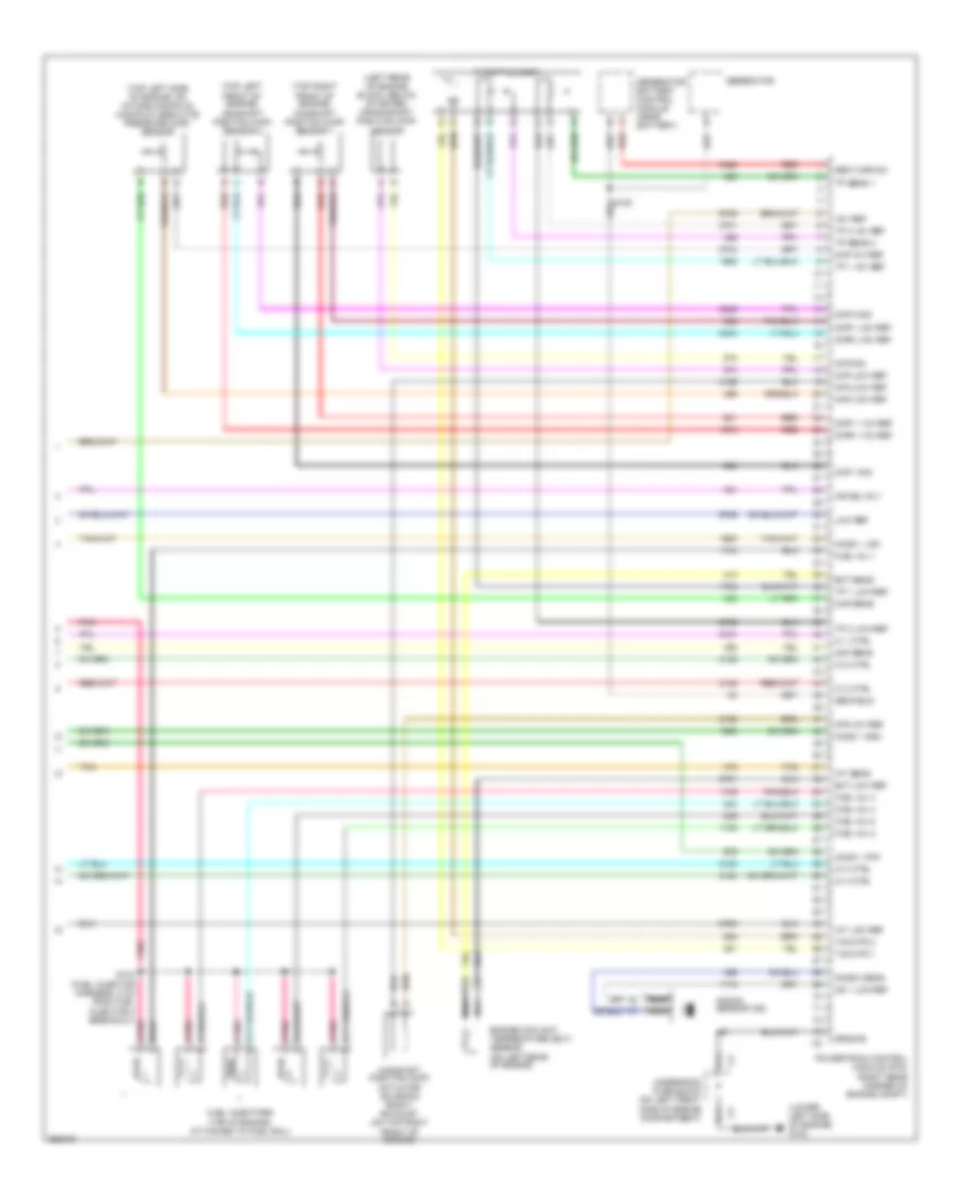
3.7L, Engine Performance Wiring Diagram (4 of 5) for Isuzu i-370 LS 2007
List of elements for 3.7L, Engine Performance Wiring Diagram (4 of 5) for Isuzu i-370 LS 2007:
- (2wd: on left rear of tranmission) (4wd: on left rear of transfer case) vehicle speed sensor (vss)
- B11
- C11
- Control
- D11
- E11
- Erls fuse 27 15a
- Evaporative emission (evap) canister purge solenoid (left side of engine, below intake)
- F11
- G102 (lower left side of engine)
- G103 (lower left side of engine)
- Ground
- Hot in run & start
- Iat
- If equipped
- Ign fuse 23 15a
- Ignition
- Ignition coils
- Injector fuse 22 15a
- Intake air temperature (iat)/ mass air flow (maf) sensor (in air intake duct, top right of engine)
- Maf
- Nca
- Plug
- Pnk
- Secondary air injection (air) solenoid (upper right side of engine)
- Spark plug
- Tan
- Trans fuse 24 10a
- Underhood fuse block (on left front side of engine compartment)
- Underhood fuse block (on left front side of engine compt)
3.7L, Engine Performance Wiring Diagram (5 of 5) for Isuzu i-370 LS 2007
List of elements for 3.7L, Engine Performance Wiring Diagram (5 of 5) for Isuzu i-370 LS 2007:
- (left rear of engine block, below starter) crankshaft position (ckp) sensor
- (lower left side of engine) g102
- (top left front of engine) camshaft position (cmp) sensor 2
- (top left side of engine, on intake manifold) manifold absolute pressure (map) sensor
- (top right front of engine) camshaft position (cmp) sensor 1
- +5v ref
- A11
- Air sol rly
- B11
- Camshaft position (cmp) actuator solenoid bank 1 exhaust (on top right front of engine)
- Ckp low ref
- Ckp sig
- Cmp 1 sig
- Cmp 2 sig
- Cmp1 +12v ref
- Cmp1 low ref
- Cmp2 +12v ref
- Cmp2 low ref
- Cpa +5v ref
- Cpa low ref
- Ect low ref
- Ect sens
- Engine coolant temperature (ect) sensor (on left rear of engine)
- Fuel inj 1
- Fuel inj 2
- Fuel inj 3
- Fuel inj 4
- Fuel inj 5
- Fuel injectors (top of engine, attached to fuel rail)
- Gen field
- Gen turn-on
- Generator
- Generator battery control module (near battery)
- Ground
- Ho2s 1 high
- Ho2s 1 htr
- Ho2s 1 low
- Iat low ref
- Iat sens
- Ic 1 ctrl
- Ic 2 ctrl
- Ic 3 ctrl
- Ic 4 ctrl
- Ic 5 ctrl
- Knock sens
- Knock sensor (ks)
- Ks 1 low ref
- Low ref
- Maf sens
- Map +5v ref
- Map low ref
- Map sens
- Nca
- Pnk
- Pnk a
- Powertrain control module (pcm) (right rear corner of engine compt)
- Red
- S103 (fuel injector harness, 5 cm from fuel injector 4 breakout)
- Tac mtr 1
- Tac mtr 2
- Tan
- Throttle body
- Tp 1 +5v ref
- Tp 1 low ref
- Tp 2 +5v ref
- Tp 2 low ref
- Tp sens 1
- Tp sens 2
- Underhood fuse block (on left front side of engine compartment)

 Čeština
 Dansk
Dansk Deutsch
 Ελληνικά
 English
 English
 Español
 Suomi
Suomi Français
 Français
 עברית
עברית Hrvatski
 Magyar
 Italiano
 日本語
日本語 한국어
한국어 Polski
 Português
 Português
 Română
 Русский
 Slovenčina
 Slovenščina
 Svenska
 Türkçe
 中文 (中国)