POWER DISTRIBUTION
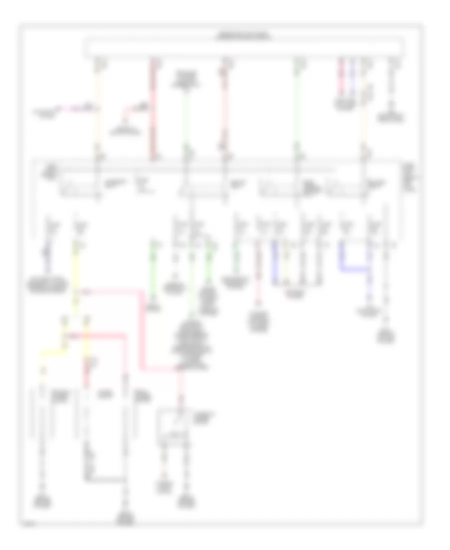
Power Distribution Wiring Diagram (1 of 3) for Infiniti Q60 Journey 2014


List of elements for Power Distribution Wiring Diagram (1 of 3) for Infiniti Q60 Journey 2014:
- (behind right side of dash) m95
- (or red)
- 12g
- Acc ind
- Anti-lock brakes system
- Battery
- Bcm (body control module) (behind right kick panel)
- Body computer system
- Convertible
- Cooling fans system
- Coupe
- Cpu
- Door locks & starting/charging systems
- E101
- E103
- E106
- E201
- E202
- Engine controls system
- Exterior lights & cruise control systems
- Fuse & fusible link block
- Fuse 10a
- Fuse 15a
- Fuse block (j/b) (behind left kick panel)
- Fusible link a 140a
- Fusible link b 100a
- Fusible link c 80a
- Fusible link d 60a
- Fusible link e 80a
- Fusible link f 50a
- Fusible link g 30a
- Fusible link h 30a
- Fusible link holder (coupe) battery terminal w/ fusible link (convertible) (coupe: right rear of engine compt)
- Fusible link i 50a
- Fusible link k 40a
- Fusible link l 30a
- Fusible link m 50a
- Fusible link n 50a
- Fusible link o (convertible) 30a
- Horns system
- Instrument cluster, air conditioning & transmissions systems
- Interior lights system
- Ipdm e/r (intelligent power distribution module engine room) (at right rear of engine compt)
- Lock ind
- M119
- M121
- M122
- M123
- Navigation & sound systems
- Nca
- On ind
- Passive restraints system
- Pnk
- Power tops & trunk, tailgate, fuel doors systems
- Power tops system
- Push button ignition switch
- Push switch
- Red
- Seats system
- Seats, body computer & memory systems warning & power tops systems
- Sound systems
- Starter relay
- Starting/ charging system
- Tan
- To accessory relay (diagram 2 of 3)
- To fuse block (j/b) (diagram 2 of 3)
- To ipdm e/r (intelligent power distribution module engine room) (diagram 3 of 3)
- Transmissions system
- Wiper/washer, computer data lines, instrument cluster, navigation, sound, air conditioning, mirrors systems door locks & mirrors systems
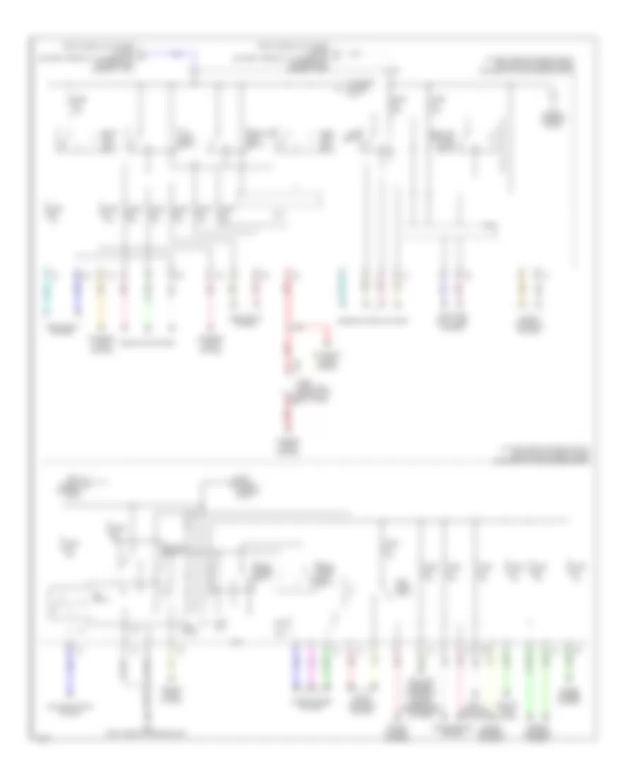
Power Distribution Wiring Diagram (2 of 3) for Infiniti Q60 Journey 2014
List of elements for Power Distribution Wiring Diagram (2 of 3) for Infiniti Q60 Journey 2014:
- (behind left end of dash)
- (behind right kick panel) bcm (body control module)
- (or pnk)
- 10c
- 10g
- 11c
- 11g
- 12c
- Accessory relay
- Air conditioning
- Air conditioning, instrument cluster, mirrors, navigation & sound systems
- Blower relay
- Cigarette lighter socket
- Computer data lines system
- Console power socket
- Cruise control, exterior lights, & shift interlock systems
- Defogger system
- E102
- E103
- E106
- Exterior lights & instrument cluster systems
- From fuse & fusible link block (diagram 1 of 3)
- From fuse 9 c (diagram 1 of 3)
- Front power socket
- Fuse 10a
- Fuse 15a
- Fuse 20a
- Fuse block (j/b) (behind left kick panel)
- Ignition relay
- Interior lights system
- M11
- M11 (behind left end of dash)
- M119
- M122
- M123
- M133
- M151
- M95 (behind right side of dash)
- Memory & seats systems
- Navigation system
- Passive restraints system
- Pnk
- Power socket
- Rear window defogger relay
- Red
- Seats system
- System
- Tan
- Warning headlights, electronic power steering, computer data lines, sound, transmissions, air conditioning, seats, instrument cluster, navigation & mirrors systems
Power Distribution Wiring Diagram (3 of 3) for Infiniti Q60 Journey 2014
List of elements for Power Distribution Wiring Diagram (3 of 3) for Infiniti Q60 Journey 2014:
- (at right rear of engine compt) ipdm e/r (intelligent power distribution module engine room)
- (diagram 3 of 3)
- +ig
- A/c relay
- Air comp
- Air conditioning system
- Anti-lock brakes, electronic power steering & transmissions systems
- Body computer system
- Computer data lines system
- Cooling fans system
- Cpu
- Cruise control system
- E103
- E22 (right rear of engine compt)
- Ecm relay
- Engine controls system
- Exterior lights system
- F/wip hi rly
- F/wip rly
- From fuse 51 f
- From fuse 58 e
- From fusible link holder (coupe) battery terminal w/ fusible link (convertible) (diagram 1 of 3)
- Front fog lamp relay
- Front wiper high relay
- Front wiper relay
- Fuel pump relay
- Fuse 10a
- Fuse 15a
- Fuse 30a
- Fuse block (j/b) (behind left kick panel) m2
- Head lamp high relay
- Headlamp low relay
- Headlights system
- Ignition relay
- Interior lights system
- Pnk
- Red
- Tail- lamp relay
- Tan
- Throttle control motor relay
- To fuse 49 (diagram 3 of 3)
- To fuse 60 (diagram 3 of 3)
- Transmissions system
- Wiper/ washer system
- Wiper/washer system

 Čeština
 Dansk
Dansk Deutsch
 Ελληνικά
 English
 English
 Español
 Suomi
Suomi Français
 Français
 עברית
עברית Hrvatski
 Magyar
 Italiano
 日本語
日本語 한국어
한국어 Polski
 Português
 Português
 Română
 Русский
 Slovenčina
 Slovenščina
 Svenska
 Türkçe
 中文 (中国)