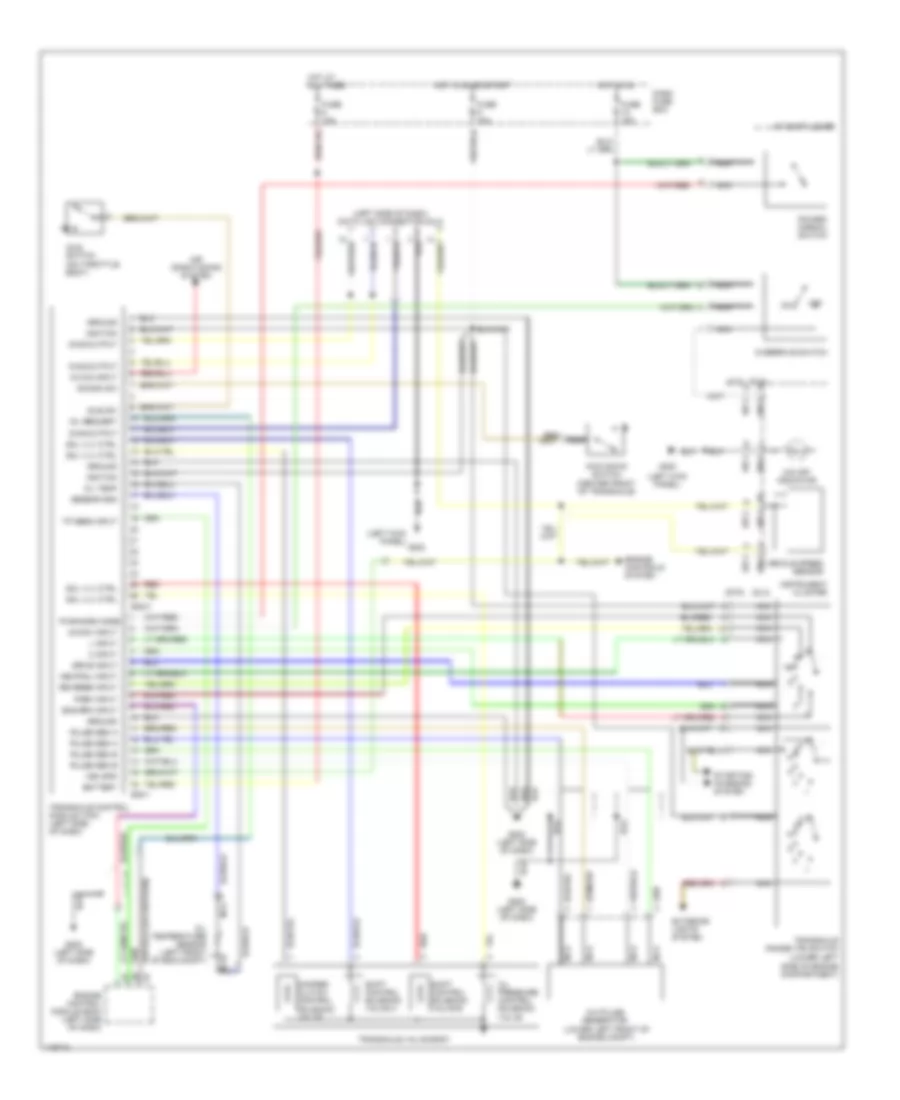
TRANSMISSION
A/T Wiring Diagram for Hyundai Accent GL 1997
List of elements for A/T Wiring Diagram for Hyundai Accent GL 1997:
- (dlx) (std)
- (left kick panel)
- (left side of dash) data link connector (dlc)
- (lower left side of engine compartment)
- (std) (dlx)
- 107-2
- 108-1
- 108-2
- 108-3
- 2 input
- A/c on input
- A/c pulse generator (lower left front of engine compt)
- A/t shift lever
- Air conditioning system
- Battery
- Damper clutch control solenoid valve
- Dash fuse box
- Diag output
- Drive input
- E38-1
- E38-2
- Eng rpm input
- Engine control module (ecm) (left side of dash)
- Engine controls system
- Exterior lights system
- Fuse 10a
- G200
- G202 (left side of dash)
- Ground
- Hot at all times
- Hot in on
- Hot in on or start
- Idle sw
- Idle switch (on throttle body)
- Ignition
- Instrument cluster
- Kick down switch (center front of transaxle)
- Kickdn sw
- L input
- Mil request
- Nca
- Nca oil temperature sensor (left front of eng compt)
- Neutral input
- O/d off indicator
- O/d sw input
- Off
- Oil pressure control solenoid valve
- Oil temp
- Overdrive switch
- Park input
- Power/ normal switch
- Pulse gen a
- Pulse gen b
- Pwr/norm mode
- Red
- Reverse input
- Sensor gnd
- Shift control solenoid valve a
- Shift control solenoid valve b
- Sol vlv ctrl
- Starting/ charging system
- Tp sens input
- Transaxle control module (tcm) (left side of dash)
- Transaxle range (tr) switch
- Transaxle valve body
- Veh spd
- Vehicle speed sensor
 Čeština
 Dansk
Dansk Deutsch
 Ελληνικά
 English
 English
 Español
 Suomi
Suomi Français
 Français
 עברית
עברית Hrvatski
 Magyar
 Italiano
 日本語
日本語 한국어
한국어 Polski
 Português
 Português
 Română
 Русский
 Slovenčina
 Slovenščina
 Svenska
 Türkçe
 中文 (中国)
 Nederlands