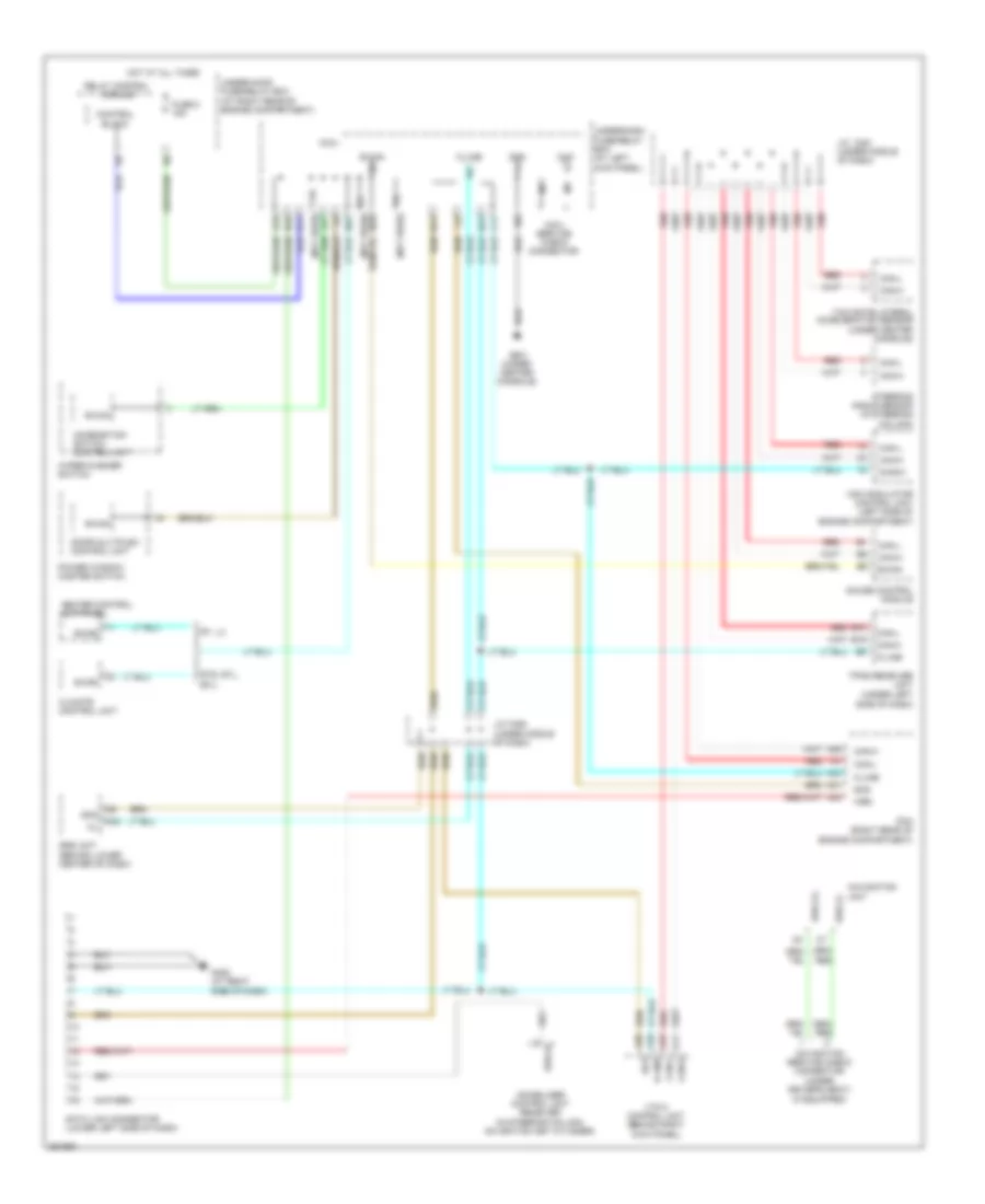
COMPUTER DATA LINES
Computer Data Lines Wiring Diagram for Honda Ridgeline RTL 2007
List of elements for Computer Data Lines Wiring Diagram for Honda Ridgeline RTL 2007:
- (if equipped)
- (not used)
- A24
- A31
- A36
- A42
- A43
- B-can
- B10
- B19
- C11
- Can-h
- Can-l
- Chk
- Climate control unit
- Combination switch control unit
- Control block
- D10
- D11
- Data link connector (lower left side of dash)
- Diag (+)
- Diag (-)
- Diag-h
- Diag-k
- Door multiplex control unit
- Fuse 8 15a
- G402 (at right side of dash)
- G501 (under center console)
- Gauge control module
- Gnd
- Heater control unit-panel
- Hot at all times
- Immobilizer control unit receiver (in steering column, on ignition key cylinder)
- J/c c451 (under middle of dash)
- J/c c452 (under middle of dash)
- K-line
- Micu
- Micu service check connector
- N10
- N13
- N14
- N22
- N28
- Navigation service check connector (under driver's seat)
- Navigation unit
- Pcm (right rear of engine compartment)
- Power window master switch
- Red
- Red a22
- Relay control module
- Rt, lx
- Rts, rtl, ex-l
- Scs
- Side of dash)
- Srs unit (behind lower center of dash)
- Steering angle sensor (in steering column)
- Tpms receiver unit (under left
- Under-dash fuse/relay box (at left kick panel)
- Under-hood fuse/relay box (at right rear of engine compartment)
- Vsa modulator control unit (left side of engine compartment)
- Vtm-4 control unit (behind right kick panel)
- Wen
- Wiper/washer switch
- X18
- X27
- Yaw rate-lateral acceleration sensor (under center console)
 Čeština
 Dansk
Dansk Deutsch
 Ελληνικά
 English
 English
 Español
 Suomi
Suomi Français
 Français
 עברית
עברית Hrvatski
 Magyar
 Italiano
 日本語
日本語 한국어
한국어 Polski
 Português
 Português
 Română
 Русский
 Slovenčina
 Slovenščina
 Svenska
 Türkçe
 中文 (中国)
 Nederlands