CRUISE CONTROL
2.4L
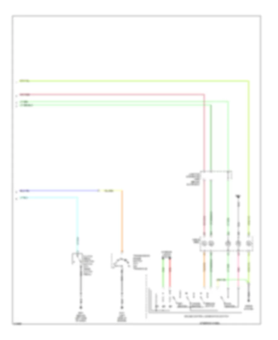
2.4L, Cruise Control Wiring Diagram (1 of 2) for Honda Accord Hybrid 2007


List of elements for 2.4L, Cruise Control Wiring Diagram (1 of 2) for Honda Accord Hybrid 2007:
- (below left side of dash) junction connector c406
- (ex-l w/ nav) (under right side of dash) junction connector c555
- A18
- A20
- A21
- A23
- A24
- A25
- A26
- App sensor (right side of engine comp)
- Apsa
- Apsb
- B19
- B20
- Brake pedal position switch (near brake pedal)
- C18
- Can high sig
- Can low sig
- Control block
- Cruise control indicator
- Cruise control main switch indicator
- D15
- Dbw m+
- Dbw m-
- Dbwrly
- Dimming circuit cruise control
- Drive circuit
- Drive input
- E11
- E22
- E24
- Ecm/pcm (behind middle of dash)
- Engine controls system
- Fuse 1 15a
- Fuse 13 20a
- Fuse 18 15a
- Fuse 21 7.5a
- Fuse 7 7.5a
- G101 (left side of engine)
- G503
- Gauge control module
- Gauges/ indicators
- Horn relay
- Hot at all times
- Hot in on or start
- Junction connector c404 (below left side of dash)
- Junction connector c405 (below left side of dash)
- Junction connector c556 (behind glove box)
- Mrly
- N21
- N29
- Network transceiver fast controller area
- Output shaft (countershaft) speed sensor (in transmission housing)
- Pg2
- Pgm-fi main relay 1
- Red
- Relay control module
- Sedf
- Sefd
- Sensor input
- Sg1
- Sg2
- Sw input
- Switch input
- Thl1
- Thl2
- Throttle actuator control module (behind glove box)
- Throttle actuator control module relay (behind glove box)
- Tp sensor/throttle actuator (on throttle body)
- Under-dash fuse/relay box (behind left kick panel)
- Under-hood fuse/relay box (left rear of engine compt)
- Vcc
- Vcc1
- Warning
- X23
- X28
- X34
2.4L, Cruise Control Wiring Diagram (2 of 2) for Honda Accord Hybrid 2007
List of elements for 2.4L, Cruise Control Wiring Diagram (2 of 2) for Honda Accord Hybrid 2007:
- Cable reel
- Cancel switch
- Clutch pedal position switch (m/t) (near clutch pedal)
- Cruise control combination switch
- G101 (left side of engine)
- G501
- G501 (behind left side of dash)
- Horns system
- Interior lights system
- Junction connector c556 (behind glove box)
- Main switch
- Pnk
- Red
- Resume switch
- Set switch
- Steering wheel
- Transmission range switch (a/t) (on transaxle)
3.0L
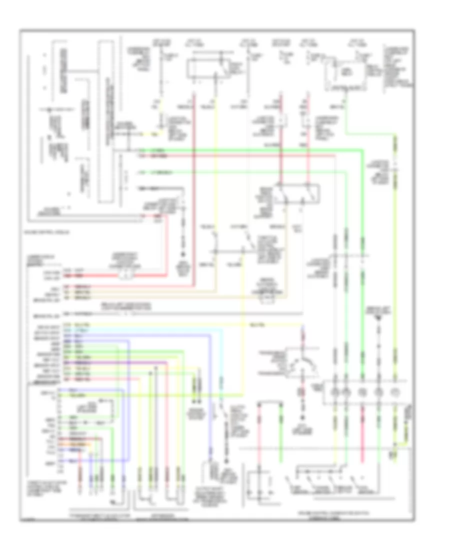
3.0L, Cruise Control Wiring Diagram, Except Hybrid for Honda Accord Hybrid 2007
List of elements for 3.0L, Cruise Control Wiring Diagram, Except Hybrid for Honda Accord Hybrid 2007:
- (behind glove box)
- (behind left side of dash) g501
- (below left side of dash) junction connector c406
- (under middle of dash) ecm/pcm
- (under right side of dash) junction connector c555
- A13
- A15
- A26
- App sensor (right side of engine comp)
- Brake pdl sw
- Brake pedal position switch (on brake pedal support)
- C19
- Cable reel
- Can high
- Can low
- Cancel switch
- Clutch pedal position switch (m/t) (under left side of dash)
- Control block
- Cruise control combination switch
- Cruise control indicator
- Cruise control main switch indicator
- D10
- D12
- D14
- D15
- Dbw m+
- Dbw m-
- Dbwrly
- Dimming circuit criuse control
- Drive input
- E25
- E26
- Engine controls system
- Fuse 1 15a
- Fuse 13 20a
- Fuse 15a
- Fuse 21 7.5a
- Fuse 7 7.5a
- G101 (left side of engine)
- G501 (behind left side of dash)
- G503 (behind glove box)
- Gauge control module
- Gauges/ indicators
- Horn relay
- Horns system
- Hot at all times
- Hot in on or start
- Junction connector c404 (below left side of dash)
- Junction connector c405 (below left side of dash)
- Junction connector c556
- Junction connector c556 (behind glove box)
- Main switch
- Mrly
- N21
- N29
- Network transceiver fast controller area
- Output shaft (countershaft) speed sensor (on transmission housing)
- Pg2
- Pgm-fi main relay 1
- Pnk
- Red
- Ref volt
- Relay control module
- Resume switch
- Sedf
- Sefd
- Sensor gnd
- Sensor input
- Sensor output
- Set switch
- Steering wheel
- Switch input
- Thl1
- Thl2
- Throttle actuator control module (under right side of dash)
- Throttle actuator control module relay (3.0l: behind left side of glove box)
- Tp sensor/throttle actuator (on throttle body)
- Transmission range switch (a/t) (on transmission)
- Under-dash fuse/relay box (behind left kick panel)
- Under-hood fuse/relay box (on left rear corner of engine compt, forward of strut tower)
- Vcc
- Warning drive circuit
- X23
- X28
- X34
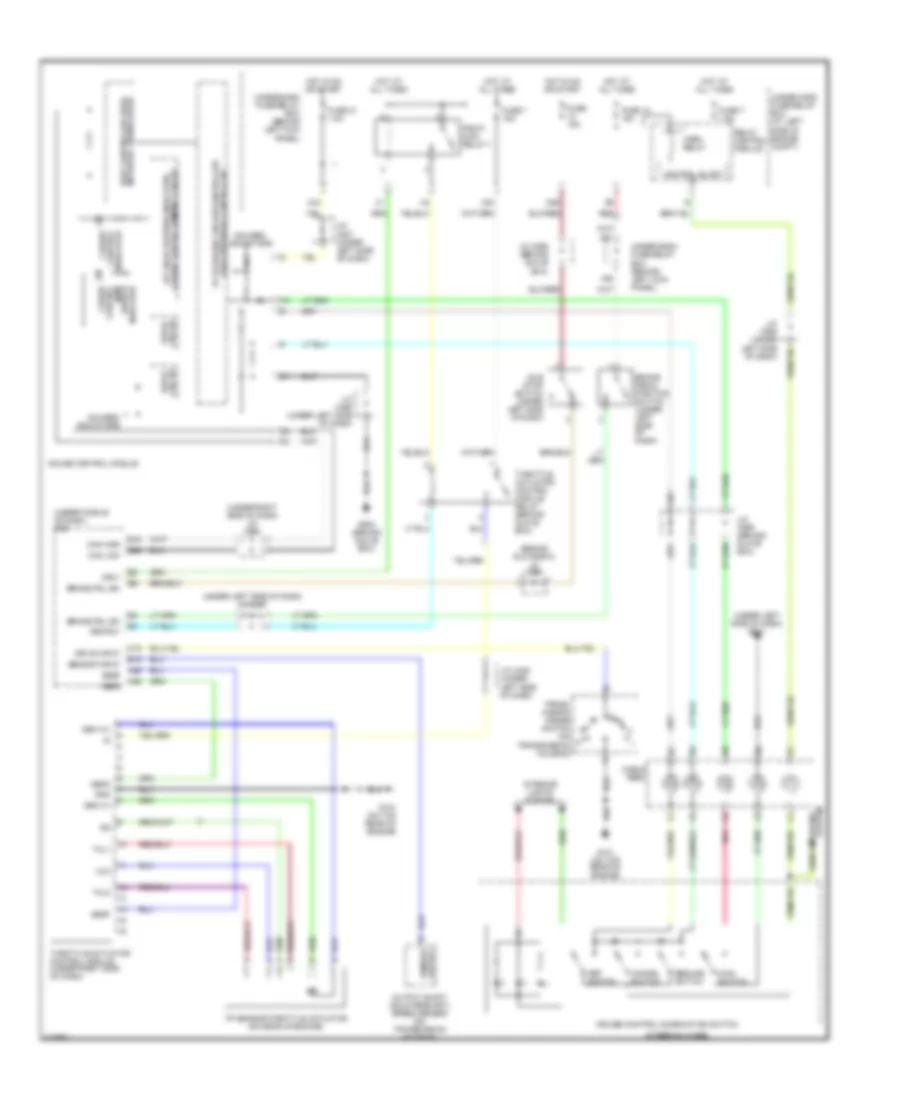
3.0L, Cruise Control Wiring Diagram, Hybrid for Honda Accord Hybrid 2007
List of elements for 3.0L, Cruise Control Wiring Diagram, Hybrid for Honda Accord Hybrid 2007:
- (behind glove box)
- (under left side of dash) g501
- (under left side of dash) j/c c407
- (under middle of dash) pcm
- (under right side of dash) j/c c555
- 5v stabilize circuit/controller area network controller
- A25
- A26
- B19
- Brake pdl sw
- Brake pedal position switch (under left side of dash)
- C19
- Cable reel
- Can high
- Can low
- Cancel switch
- Control block
- Cruise control combination switch
- Cruise control dimming circuit a/t gear position indicator/
- Cruise control indicator
- Cruise control main switch indicator
- Dbw m+
- Dbw m-
- Dbwrly
- Drive circuit
- Drive input
- E15
- E26
- Fuse 1 15a
- Fuse 13 15a
- Fuse 15a
- Fuse 21 7.5a
- Fuse 7 7.5a
- G101 (on top rear of engine)
- G503 (behind glove box)
- Gauge control module
- Gauges/ indicators
- Gnd
- Horn relay
- Horns system
- Hot at all times
- Hot in on or start
- Idle stop switch (under left side of dash)
- Interior lights system
- J/c c406 (under left side of dash)
- J/c c407 (under left side of dash)
- J/c c408 (under left side of dash)
- J/c c556
- J/c c556 (behind glove box)
- J/c c558 (under left side of dash)
- Main switch
- Mrly
- N21
- N29
- Network transceiver fast controller area
- Output shaft (countershaft) speed sensor (on transmission housing)
- Pgm-fi main relay 1
- Pnk
- Red
- Relay control module
- Resume switch
- Sedf
- Sefd
- Sensor input
- Sensor output
- Set switch
- Steering wheel
- Thl1
- Thl2
- Throttle actuator control module (under right side of dash)
- Throttle actuator control module relay (behind glove box)
- Tp sensor/throttle actuator (on rear of engine)
- Trans- mission range switch (on transmission housing)
- Under-dash fuse/relay box (behind left kick panel)
- Under-hood fuse/relay box (at left side of engine compt)
- Vcc
- X23
- X28
- X34

 Čeština
 Dansk
Dansk Deutsch
 Ελληνικά
 English
 English
 Español
 Suomi
Suomi Français
 Français
 עברית
עברית Hrvatski
 Magyar
 Italiano
 日本語
日本語 한국어
한국어 Polski
 Português
 Português
 Română
 Русский
 Slovenčina
 Slovenščina
 Svenska
 Türkçe
 中文 (中国)