
 Čeština
 Dansk
Dansk Deutsch
 Ελληνικά
 English
 English
 Español
 Suomi
Suomi Français
 Français
 עברית
עברית Hrvatski
 Magyar
 Italiano
 日本語
日本語 한국어
한국어 Polski
 Português
 Português
 Română
 Русский
 Slovenčina
 Slovenščina
 Svenska
 Türkçe
 中文 (中国)

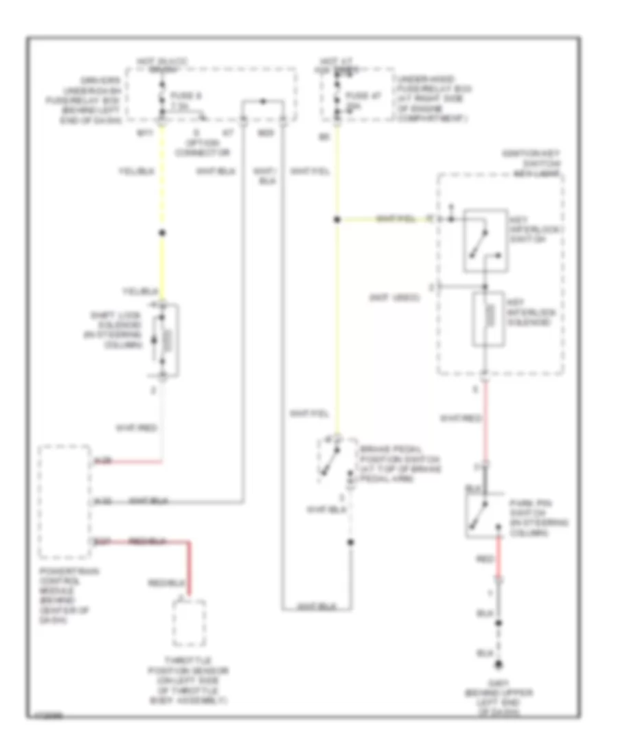
SHIFT INTERLOCK
Shift Interlock Wiring Diagram for Honda Pilot LX 2004
List of elements for Shift Interlock Wiring Diagram for Honda Pilot LX 2004:

ANTI-LOCK BRAKESAIR CONDITIONINGANTI-THEFTCOOLING FANBODY CONTROL MODULESCOMPUTER DATA LINESGROUND DISTRIBUTIONENGINE PERFORMANCECRUISE CONTROLHEADLIGHTSDEFOGGERSEXTERIOR LIGHTSHORNINSTRUMENT CLUSTERNAVIGATIONPOWER DISTRIBUTIONINTERIOR LIGHTSPOWER WINDOWSPOWER DOOR LOCKSPOWER SEATSPOWER MIRRORSRADIOSHIFT INTERLOCKSUPPLEMENTAL RESTRAINTSWARNING SYSTEMSSTARTING/CHARGINGTRANSMISSIONWIPER/WASHER