INSTRUMENT CLUSTER
Instrument Cluster Wiring Diagram (1 of 2) for BMW 740i 2001


List of elements for Instrument Cluster Wiring Diagram (1 of 2) for BMW 740i 2001:
- (left door sill) x1108
- Air conditioning system
- Anti-lock brakes system
- Computer data lines system
- Dual temperature sensor
- Instrument cluster
- Integrated instrument cluster control module (ike)
- Interior lights system
- Sound systems
- X10113
- X10114
- X16
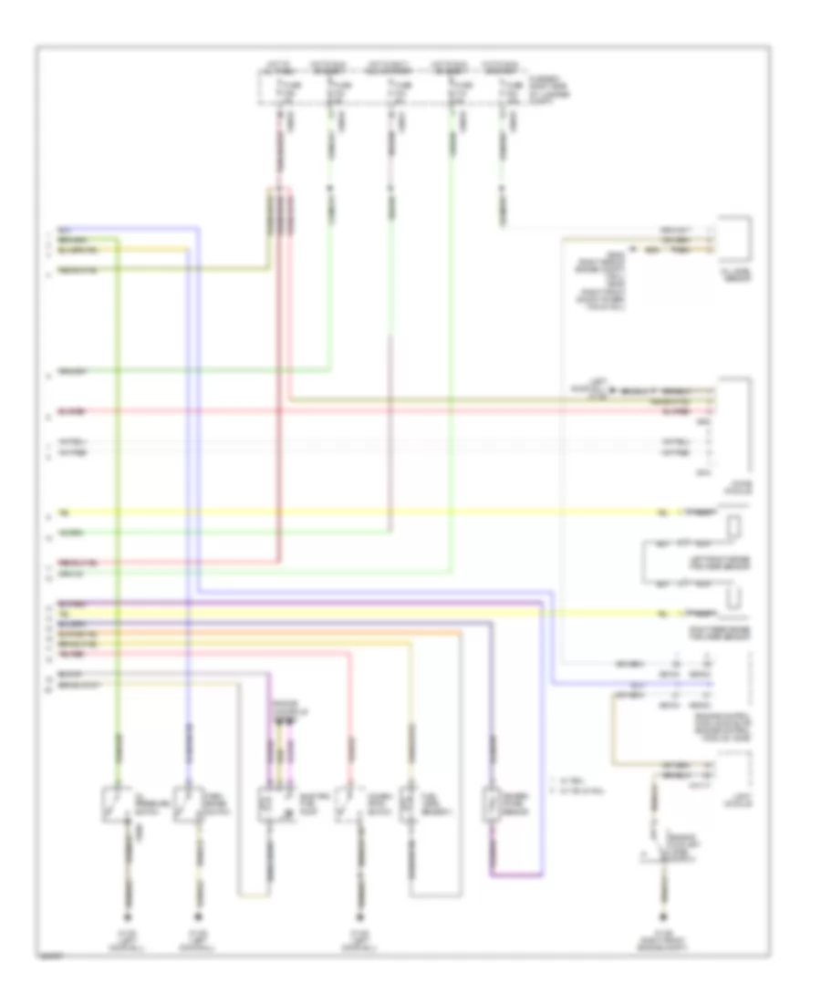
Instrument Cluster Wiring Diagram (2 of 2) for BMW 740i 2001
List of elements for Instrument Cluster Wiring Diagram (2 of 2) for BMW 740i 2001:
- (left door sill) x1108
- Chime module
- Combin- ation switch
- Electric fuel pump
- Engine control module (dme) or engine control module i (dme)
- Engine controls system
- Engine coolant level switch
- Fuel level sensor ii
- Fuse box (right side of luggage compt)
- Fuse f18 5a
- Fuse f22 10a
- Fuse f23 5a
- Fuse f26 5a
- Fuse f43 5a
- Hot at all times
- Hot in accy, run or start
- Hot in run or start
- Left front brake pad wear sensor
- Light module
- Nca
- Oil level sensor
- Oil pressure switch
- Park brake switch
- Right rear brake pad wear sensor
- Temper- ature sensor
- W/ 740i & 740il
- W/ 750il
- X10016
- X10017
- X10117
- X1106 (right front engine compt)
- X1108 (left door sill)
- X1868
- X518
- X522
- X60003
- X60004
- X60103
- X60104
- X6454 (right side of engien compt) (750il) x6452 (right front shock tower) (740i & 740il)

 Čeština
 Dansk
Dansk Deutsch
 Ελληνικά
 English
 English
 Español
 Suomi
Suomi Français
 Français
 עברית
עברית Hrvatski
 Magyar
 Italiano
 日本語
日本語 한국어
한국어 Polski
 Português
 Português
 Română
 Русский
 Slovenčina
 Slovenščina
 Svenska
 Türkçe
 中文 (中国)