ANTI-LOCK BRAKES
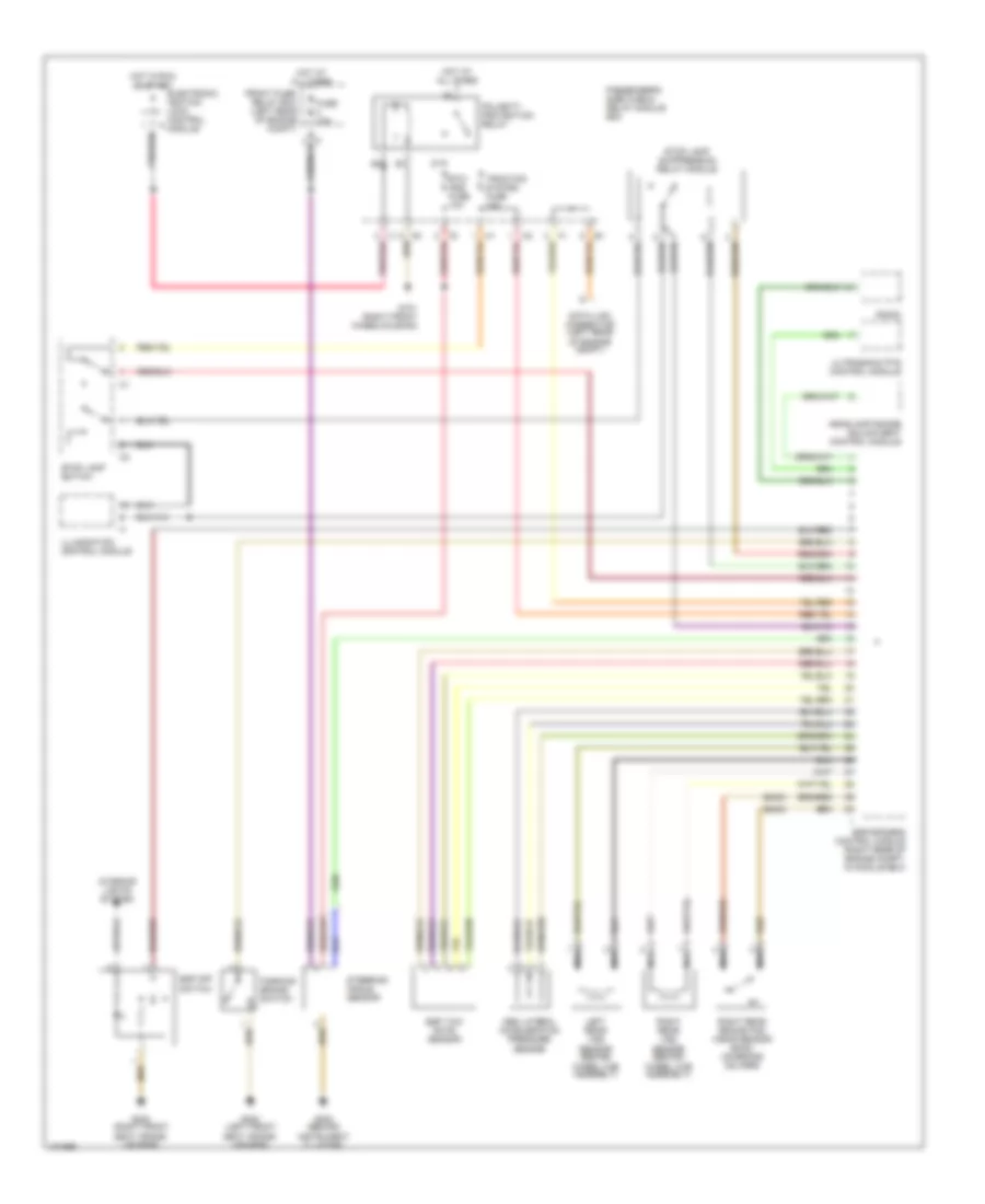
Anti-lock Brake Wiring Diagrams (1 of 2) for Mercedes-Benz E320 4Matic 2000
 https://portal-diagnostov.com/license.html
Automotive Electricians Portal FZCO
Automotive Electricians Portal FZCO
https://portal-diagnostov.com/license.html
https://portal-diagnostov.com/license.html
Automotive Electricians Portal FZCO
Automotive Electricians Portal FZCO
List of elements for Anti-lock Brake Wiring Diagrams (1 of 2) for Mercedes-Benz E320 4Matic 2000:
- Asr/ets/esp hydraulic unit
- Brake booster (bas)
- Computer data lines system
- Driver's side fuse & relay module box
- Esp brake pressure sensor
- Esp/sps/bas control module (right rear of engine compt, in module box)
- Front axle switchover
- Front axle vacuum
- Front fuse/ relay box (left rear of engine compt)
- Fuse 40a
- G102 (left front wheelhousing)
- High pressure/ return pump
- High pressure/ return pump relay module
- Hot at all times
- Left front brake pad wear sensor (on brake caliper)
- Left front hold
- Left front release
- Left front vss sensor (behind wheel hub assembly)
- Left rear hold
- Left rear release
- Nca
- Pnk
- Rear axle switchover
- Rear axle vacuum
- Red
- Release switch
- Right front brake pad wear sensor (on brake caliper)
- Right front hold
- Right front release
- Right front vss sensor (behind wheel hub assembly)
- Right rear hold
- Right rear release
- Solenoid valve
- Sps solenoid valve (on steering rack)
- Terminal block (x12/3) (left rear of engine compt)
- Terminal block (x4) (left footwell)
- Travel sensor
Anti-lock Brake Wiring Diagrams (2 of 2) for Mercedes-Benz E320 4Matic 2000
List of elements for Anti-lock Brake Wiring Diagrams (2 of 2) for Mercedes-Benz E320 4Matic 2000:
- (e430)
- Abs lateral acceleration pressure sensor
- Data link connector (left rear of engine compt)
- Electronic ignition lock control module
- Esp off switch
- Esp yaw rate sensor
- Esp/sps/bas control module (right rear of engine compt, in module box)
- Etc/ ads fuse 10a
- Front fuse/ relay box (left rear of engine compt)
- Fuse 10a
- G101 (right front wheelhousing)
- G202 (behind instrument cluster)
- G203 (right front seat cross- member)
- G300 (left front seat cross- member)
- Headlamp range adjustment control module
- Hot at all times
- Hot in run or start
- Illumination control module
- Interior lights system
- Left rear vss sensor (behind wheel hub assembly)
- Nca
- Parking brake switch
- Passenger's side fuse & relay module box
- Pnk/red
- Polarity protection relay
- Radio
- Right rear brake pad wear sensor (e430) (on brake caliper)
- Right rear vss sensor (behind wheel hub assembly)
- Steering angle sensor
- Stop lamp suppression relay module
- Stop lamp switch
- Traction system fuse 10a
- Ultrasonic pts control module

 Čeština
 Dansk
Dansk Deutsch
 Ελληνικά
 English
 English
 Español
 Suomi
Suomi Français
 Français
 עברית
עברית Hrvatski
 Magyar
 Italiano
 日本語
日本語 한국어
한국어 Polski
 Português
 Português
 Română
 Русский
 Slovenčina
 Slovenščina
 Svenska
 Türkçe
 中文 (中国)