Čeština
 Dansk
Dansk Deutsch
 Ελληνικά
 English
 English
 Español
 Suomi
Suomi Français
 Français
 עברית
עברית Hrvatski
 Magyar
 Italiano
 日本語
日本語 한국어
한국어 Polski
 Português
 Português
 Română
 Русский
 Slovenčina
 Slovenščina
 Svenska
 Türkçe
 中文 (中国)

Chrysler Prowler 2002 - ELECTRICAL Fuses & Circuit Breakers
Chrysler Prowler 2002 - MICRO RELAY BANK DESCRIPTION & OPERATION
A relay bank is located behind and above the glove box. It holds six micro relays and blade-type automatic resetting circuit breakers.
All electrical current entering and leaving the micro relay bank does so through wire harnesses, which are connected to the micro relay bank. The relay bank houses 6 blade-type automatic resetting circuit breakers. Internal connection of all the micro relay bank circuits is accomplished by an intricate network of hard wiring and bus bars. For complete circuit diagrams, see appropriate WIRING DIAGRAMS article.
Circuit breakers are available for service replacement. The micro relay bank cannot be repaired and is only serviced with the instrument panel wiring harness assembly. If any internal circuit or the relay bank is faulty or damaged, the entire instrument panel wire harness must be replaced.
Chrysler Prowler 2002 - FUSE BLOCK DESCRIPTION & OPERATION
Fuse block is located in the left endcap of the instrument panel. The left instrument panel endcap is a snap-fit fuse access cover that conceals the fuse block and fuses. A fuse puller and spare fuse holders are located on the back of the endcap, as well as the fuse layout to ensure proper fuse identification. The left instrument panel endcap must be removed to access components other than the fuses in the fuse block.
Electrical current entering and leaving the fuse block does so through wire harnesses, which are connected to the fuse block. The fuse block houses blade type fuses. Internal connection of all the fuse block circuits is accomplished by an intricate network of hard wiring and bus bars. For complete circuit diagrams, see appropriate WIRING DIAGRAMS article.
Fuses and circuit breakers are available for service replacement. The fuse block unit cannot be repaired and is only serviced with the instrument panel wiring harness assembly. If any internal circuit or the fuse block is faulty or damaged, the entire instrument panel wire harness and fuse block assembly must be replaced.
Chrysler Prowler 2002 - REMOVAL & INSTALLATION
WARNING: On vehicles equipped with airbags, refer to electrical, restraints before attempting any steering wheel, steering column, or instrument panel component diagnosis or service. Failure to take the proper precautions could result in accidental airbag deployment and possible personal injury.
NOTE: The Fuse Block is serviced with the instrument panel wire harness. If service is required to the fuse block, instrument panel wiring harness must be replaced.
- Disconnect and isolate battery negative cable. The instrument panel must be removed from the vehicle. See appropriate INSTRUMENT PANEL article.
- With the instrument panel on the bench, remove trim from instrument panel enough to gain access to all screws and connectors to remove instrument panel wire harness with fuse block.
- Route and secure the fuse block and instrument panel wiring harness. Re-trim the panel preparing for assembly into the vehicle. Ensure wire terminals and connectors are in good condition and are properly installed.
- Install the instrument panel into the vehicle. Connect the battery negative cable.
Fig. 1: Chrysler Prowler 2002 - Component Locations - Front View Of Fuse Block
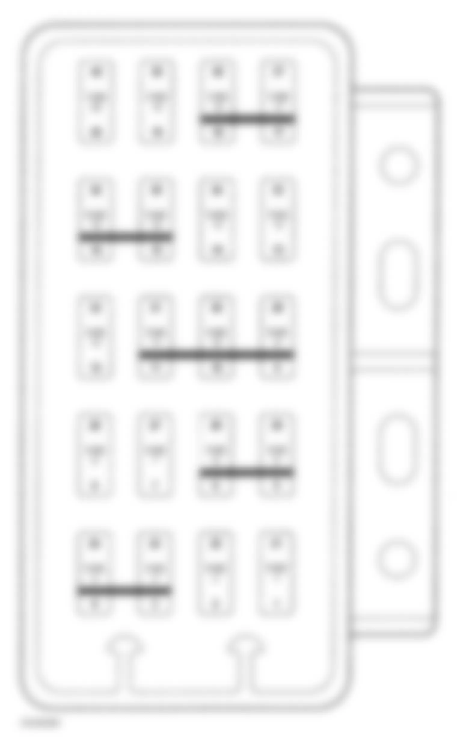

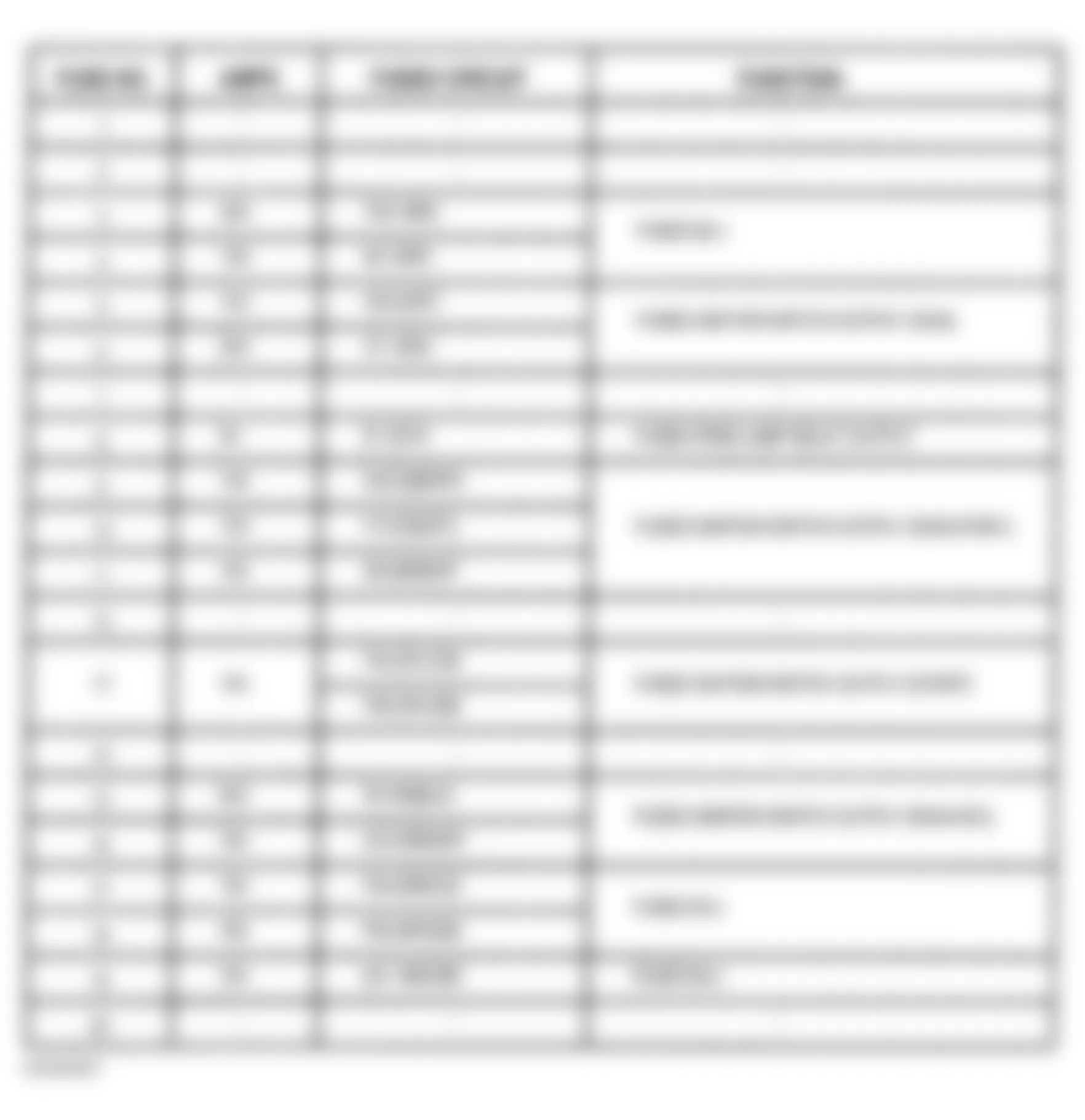
Fig. 2: Chrysler Prowler 2002 - Component Locations - Fuse Identification
Chrysler Prowler 2002 - POWER DISTRIBUTION CENTER DESCRIPTION & OPERATION
All of the electrical current distributed throughout this vehicle is directed through the standard equipment Power Distribution Center (PDC). The molded plastic PDC housing is located in the left side of the engine compartment, below and to the outboard side of the master cylinder. The PDC housing has a molded plastic cover. The PDC cover is easily removed for service access and has a convenient fuse and relay layout label affixed to the inside surface of the cover to ensure proper component identification. The PDC housing is secured in the engine compartment.
All of the PDC outputs are through the integral engine compartment wire harness. The PDC houses up to 9 maxi-fuses. The PDC also houses up to 10 mini-fuses, up to 4 full International Standards Organization (ISO) relays, and up to 8 ISO micro-relays. Internal connection of all the PDC circuits is accomplished by an intricate network of hard wiring and bus bars. For complete circuit diagrams, refer to the appropriate WIRING DIAGRAMS article.
Fusible link, fuses and relays are available for service replacement. The PDC unit cannot be repaired and is only serviced as a unit with the engine compartment wire harness. If the PDC is faulty or damaged, the engine compartment wire harness assembly must be replaced.
Chrysler Prowler 2002 - REMOVAL & INSTALLATION
NOTE: The Power Distribution Center (PDC) is serviced as a unit with the engine compartment wire harness. If any internal circuit of the PDC or the PDC housing is faulty or damaged, the entire PDC and engine compartment wire harness unit must be replaced. For complete circuit diagrams, refer to the appropriate wiring information. The wiring information includes wiring diagrams, proper wire and connector repair procedures, further details on wire harness routing and retention, as well as pin-out and location views for the various wire harness connectors, splices and grounds.
Chrysler Prowler 2002 - Removal
- Disconnect and isolate the battery negative cable. Disconnect each of the engine compartment wire harness connectors.
- Remove fasteners that secure each of the engine compartment wire harness ground eyelets to the vehicle body and chassis components.
- Disengage each of the retainers that secure the engine compartment wire harness to the vehicle body and chassis components. Remove 3 PDC mounting screw and disengage the PDC housing.
- Remove the PDC and the engine compartment wire harness from the engine compartment as a unit.
Chrysler Prowler 2002 - Installation
- Position the PDC over the mounting bracket in the engine compartment and attach with 3 screws. Align the PDC on the PDC mounting bracket.
- Route the engine compartment wire harness from the PDC through the engine compartment, engaging each of the harness retainers to the mounting provisions in the vehicle body and chassis components. Ensure clip is attached into the rail located behind the PDC.
- Install and tighten the fasteners that secure each of the engine compartment wire harness ground eyelets to the vehicle body and chassis components. Reconnect each of the engine compartment wire harness connectors.
- Torque nut retaining positive battery cable at PDC to 12 N.m (110 INCH lbs.). Reconnect the battery negative remote cable.
Fig. 3: Chrysler Prowler 2002 - Component Locations - Identifying Power Distribution Center (PDC)
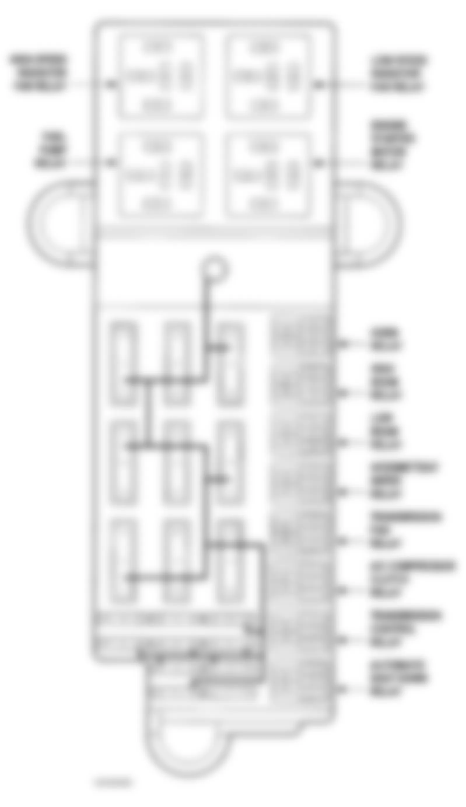
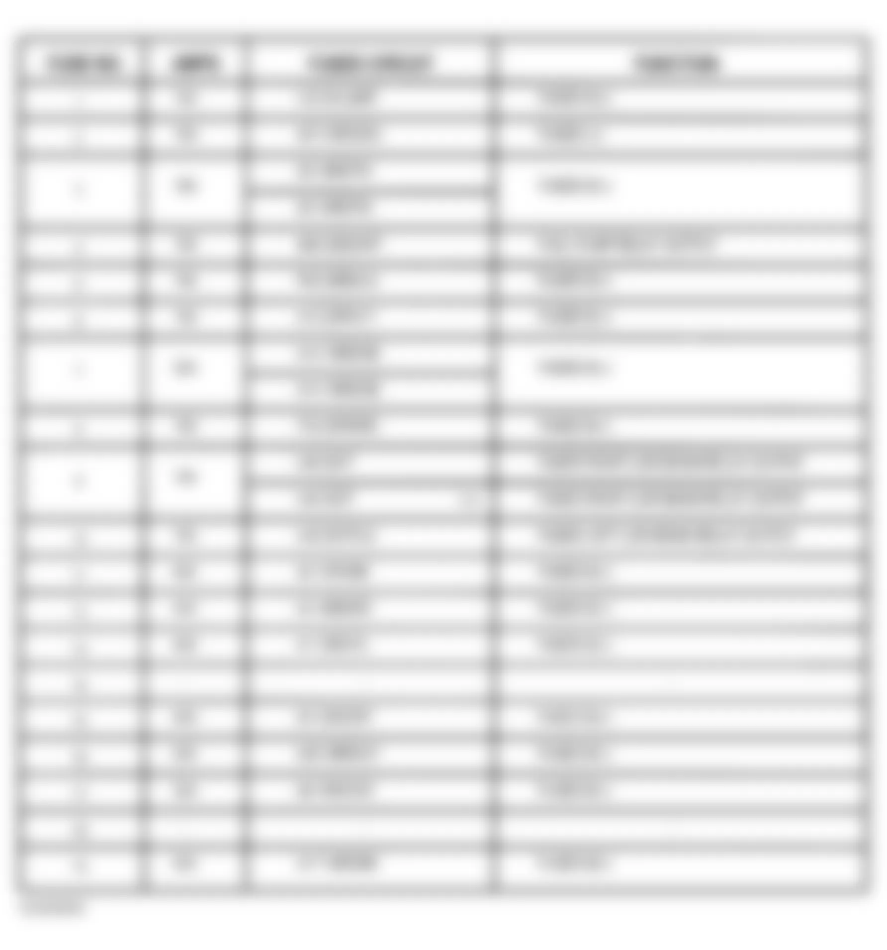
Fig. 4: Chrysler Prowler 2002 - Component Locations - Identifying PDC Fuses
Chrysler Prowler 2002 - PDC RELAYS TERMINAL IDENTIFICATION


Fig. 8: Chrysler Prowler 2002 - Component Locations - Fuel Pump Relay Terminal Identification

Fig. 9: Chrysler Prowler 2002 - Component Locations - High Beam Relay Terminal Identification


Fig. 11: Chrysler Prowler 2002 - Component Locations - Horn Relay Terminal Identification


Fig. 13: Chrysler Prowler 2002 - Component Locations - Low Beam Relay Terminal Identification