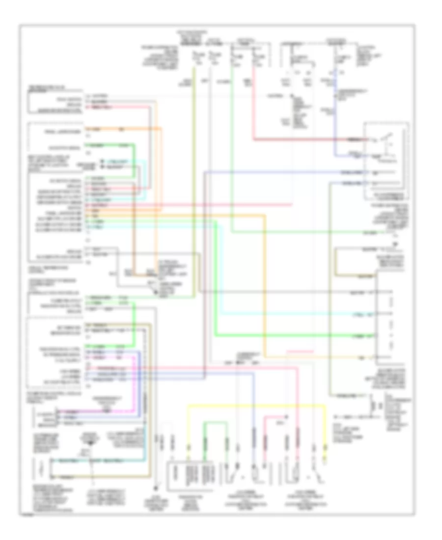
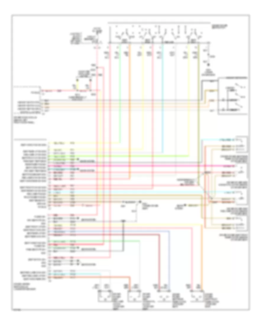
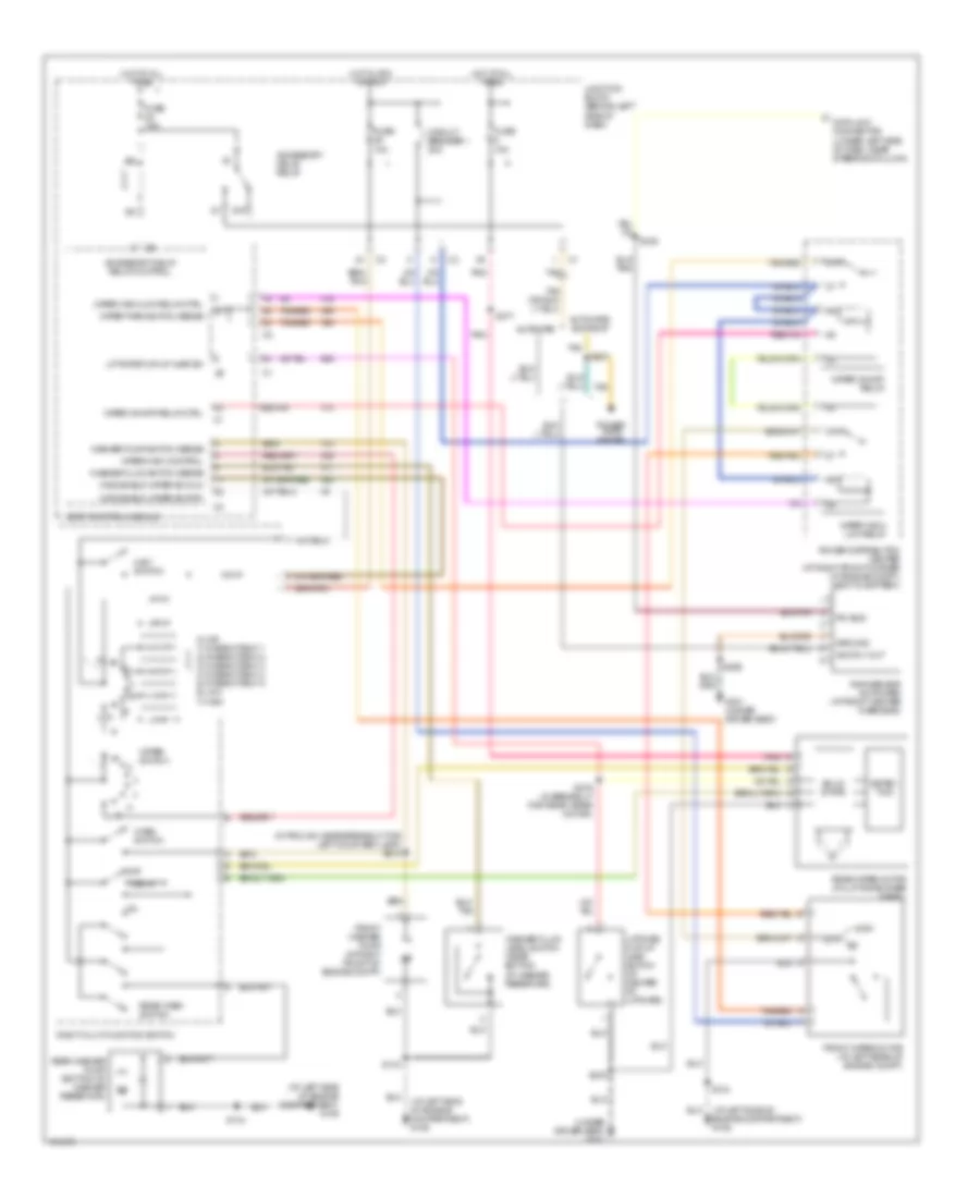
AIR CONDITIONING
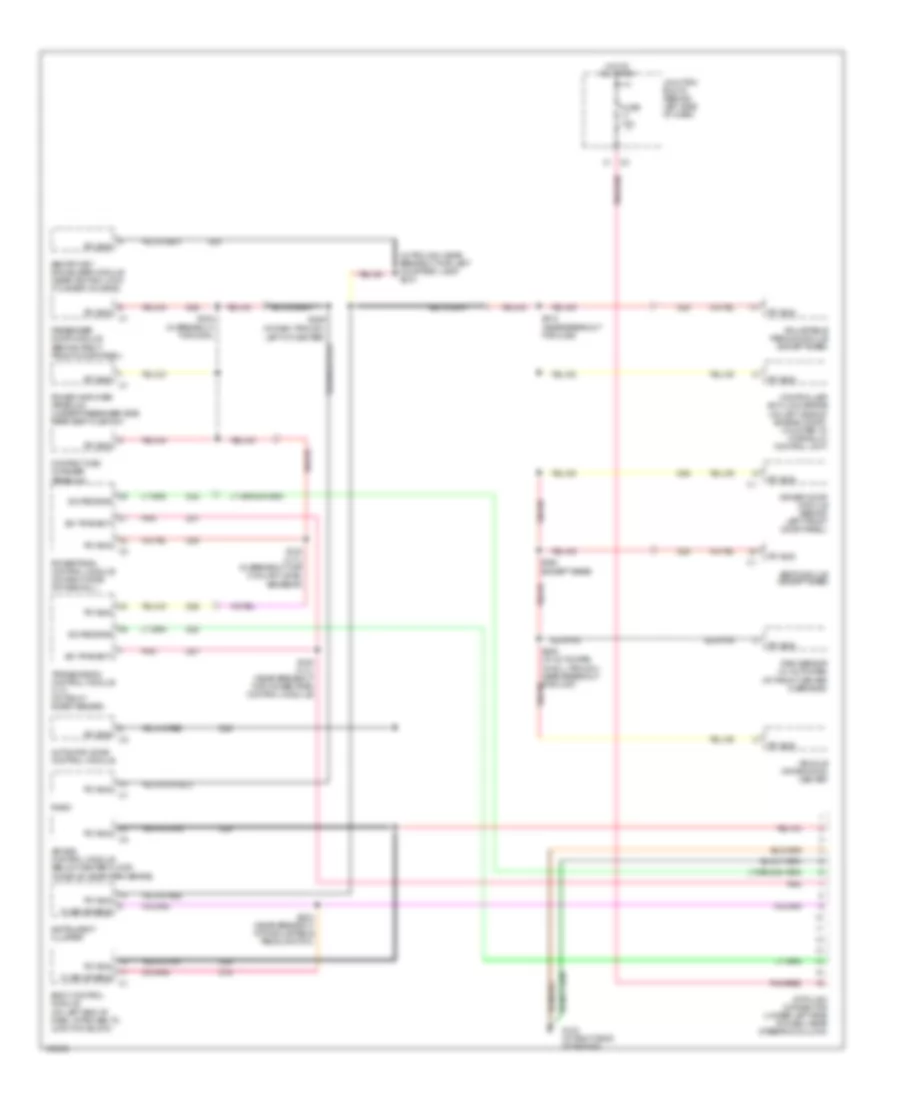
Automatic A/C Wiring Diagram for Jeep Grand Cherokee Limited 2004

List of elements for Automatic A/C Wiring Diagram for Jeep Grand Cherokee Limited 2004:
- (4.7l:near breakout for coil on plug 8) (4.0l:in breakout for c103 & c104)
- (4.7l:near breakout for fuel injector 7) (4.0l:near breakout for fuel injector 6)
- (at right front of engine compartment) (4.7l) hydraulic cooling module
- (in breakout for pdc) s180
- (in trough near breakout for passenger heated seat switch) s201
- (in trough, near breakout for passenger heated seat switch)
- (near air bag control module) g200
- (near breakout for c314) s316
- (near breakout for g104) (4.0l) s102
- (on left end of dash, attached to junction block) body control module
- (run) ignition
- A/c clutch relay ctrl
- A/c compressor clutch (4.7l:top front of engine) (4.0l: left front of engine)
- A/c compressor clutch relay
- A/c press signal
- A/c pressure transducer (behind right side radiator support)
- A/c switch signal
- Automatic zone control module
- Blower motor (behind right side of dash)
- Blower motor controller (behind right side of dash)
- Blower motor ctrl
- Blower mtr ctrl
- Blwr mtr high dr
- C100
- C102
- C103
- C13
- C18
- C32
- C33
- C35
- C56
- C79
- C81
- C94
- C95
- C96
- D25
- Data link connector (dlc) (under left side of dash, near steering column)
- Defogger sw sense
- Dr blend door dr (a)
- Dr blend door dr (b)
- Dr blnd door driver (a)
- Driver blend door motor/actuator
- Driver blnd dr driver (b)
- Ect sens sig
- Engine controls system
- Engine coolant temperature sensor (4.7l:near front of intake manifold (4.0l:at top front of engine,on thermostat housing)
- F142
- F22
- Fan relay
- Fuse 11 10a
- Fuse 15a
- Fuse 20 10a
- Fuse 21 10a
- Fuse 40a
- Fuse 7 10a
- Fused (b+)
- Fused defog rly out
- Fused relay out
- G104 (4.7l: left side of engine) (4.0l: right rear of engine)
- G108 (near power distribution center)
- G200 (near air bag control module)
- Ground
- High speed
- High speed radiator fan relay (4.0l) (in power distribution center)
- Hot at all times
- Hot in run
- Hot in run or start
- Hot w/automatic shut down (asd) relay energized
- Hot w/rear window defogger relay energized
- Junction block (behind left side of dash)
- K173
- Low speed
- Low speed radiator fan relay (4.0l) (in power distribution center)
- Mode door driver (a)
- Mode door driver (b)
- Mode door motor/actuator (on left end of heater-a/c housing)
- Panel lamps driver
- Pass blend door dr (a)
- Pass blend door dr (b)
- Pass blend dr driver (b)
- Pass blnd dr driver (a)
- Passenger blend door motor/actuator
- Pci bus
- Pnk
- Power distribution center (at right front corner of engine compartment, next to battery)
- Powertrain control module (on right side of firewall)
- Radiator fan motor (behind radiator)
- Radiator fan rly ctrl
- Radiator high speed
- Radiator low speed
- Recirc door driver (a)
- Recirc door driver (b)
- Recirculation door motor/actuator (on heater-a/c housing)
- S107
- S112
- S181
- S201
- Sens gnd
- Sensor ground
- Signal
- Z118
- Z500
Manual A/C Wiring Diagram for Jeep Grand Cherokee Limited 2004
List of elements for Manual A/C Wiring Diagram for Jeep Grand Cherokee Limited 2004:
- (4.7l:near breakout for fuel injector 7) (4.0l:near breakout for fuel injector 6)
- (at right front of engine compartment) (4.7l) hydraulic cooling module
- (in breakout for pdc) s180
- (near airbag control module) g200
- (near breakout for c314) s316
- (near breakout for g104) (4.0l) s102
- (run) ignition
- A/c comp relay ctrl
- A/c compressor clutch (4.7l: at top front engine (4.0l: at left front engine
- A/c compressor clutch relay
- A/c pressure signal
- A/c pressure transducer (behind right side radiator support)
- A/c switch signal
- Blend air dr posit ctrl
- Blower motor (behind right side of dash)
- Blower motor m1 driver
- Blower motor m2 driver
- Blower motor resistor block (bottom of heater-a/c housing, inboard of blower motor)
- Blower mtr high driver
- Blower mtr low driver
- Body control module (on left end of dash, attached to junction block)
- C103
- C13
- C18
- Courtesy lamp) s211
- Defogger relay output
- Defogger switch sense
- Defogger system
- Ect sens sig
- Engine controls system
- Engine coolant temperature sensor (4.7l:near front of intake manifold (4.0l:at top front of engine,on thermostat housing)
- F142
- Fan relay
- Fuse 15a
- Fuse 20 10a
- Fuse 21 10a
- Fuse 40a
- Fused relay out
- G104 (4.7l: left side of engine) (4.0l: right rear of engine)
- G108 (near power distribution center)
- Ground
- High speed
- High speed radiator
- High speed radiator fan relay (4.0l) (in power distribution center)
- Hot at all
- Hot at all times
- Hot in run
- Hot in run or start
- Hot w/automatic shut down (asd) relay energized
- Ignition
- Junction block (behind left side of dash)
- K173
- Low speed
- Low speed radiator
- Low speed radiator fan relay (4.0l) (in power distribution center)
- Manual temperature control
- Panel lamps driver
- Pedal switch)
- Power distribution center (at right front corner of engine compartment, next to battery)
- Powertrain control module (on right side of firewall)
- Radiator fan motor (behind radiator)
- Radiator fan rly ctrl
- S112 (4.7l:near breakout for coil on plug 8) (4.0l:in breakout for c103 & c104)
- S181
- Sensor ground
- Tan
- Temperature valve actuator
- Times
- Z500
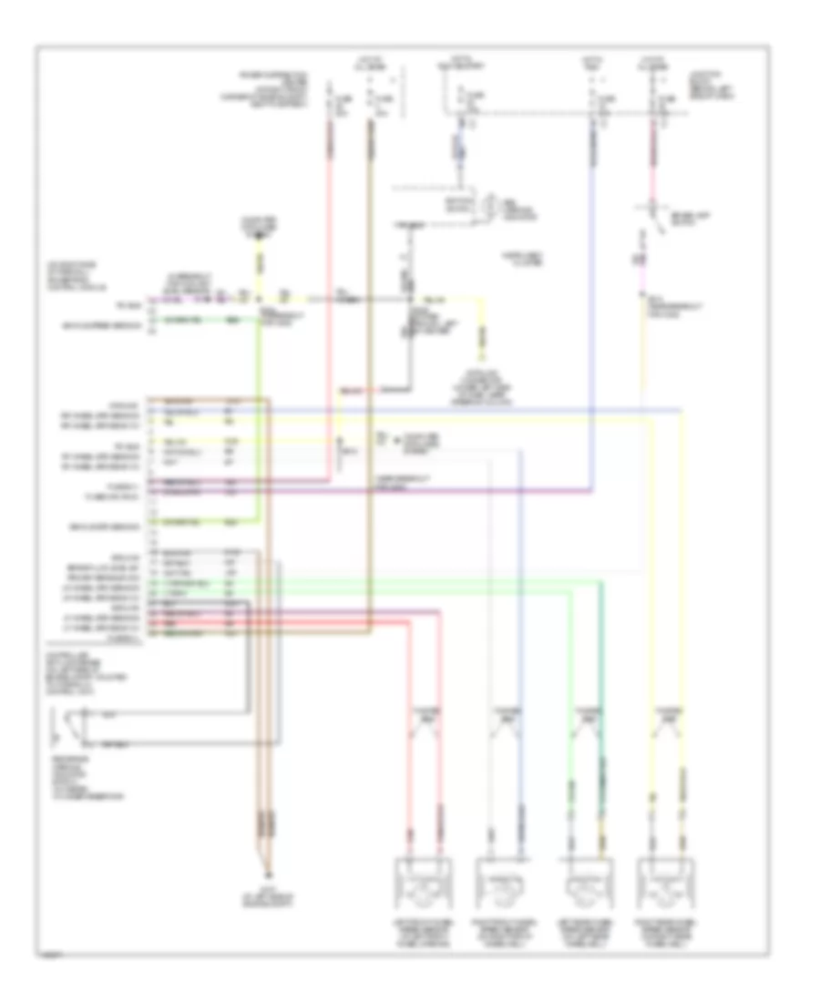
ANTI-LOCK BRAKES
Anti-lock Brakes Wiring Diagram for Jeep Grand Cherokee Limited 2004
List of elements for Anti-lock Brakes Wiring Diagram for Jeep Grand Cherokee Limited 2004:
- (near breakout for c200)
- (on right side of firewall) powertrain control module
- A10
- A20
- Abs warning indicator
- B22
- B22 b22
- Brake fluid level sw
- Brake lamp switch
- Computer data lines system
- Controller anti-lock brake (on left side of engine compt, mounted to hydraulic control unit)
- D25
- Data link connector (under left side of dash, near steering column)
- F20
- Fuse 10a
- Fuse 15a
- Fuse 20a
- Fuse 40a
- Fuse b (+)
- Fused ign (run)
- G107 (at left side of engine compt)
- Ground
- Hot at all times
- Hot in run
- Hot in run or start
- Ignition
- Instrument cluster
- Junction block (behind left side of dash)
- L50
- Left front wheel speed sensor (at left front wheel opening)
- Left rear wheel speed sensor (on left rear wheelwell)
- Lf wheel spd sens 12v
- Lf wheel spd sens sig
- Lr wheel spd sens 12v
- Lr wheel spd sens sig
- Pci bus
- Power distribution center (at right front corner of engine compt, next to battery)
- Primary brake sw sig
- Red
- Red brake warning indicator switch (in master cylinder reservoir)
- Rf wheel spd sens 12v
- Rf wheel spd sens sig
- Right front wheel speed sensor (on right front wheelwell)
- Right rear wheel speed sensor (on right rear wheelwell)
- Rr wheel spd sens 12v
- Rr wheel spd sens sig
- S130
- S226 (in dash trough, left of center)
- S312
- S313 (near breakout for c302)
- S324 (in breakout for c200)
- Switch
- Twisted pair
- Vehicle spd sens sig
- Vehicle speed sens sig
- Z101
- Z102
- Z231
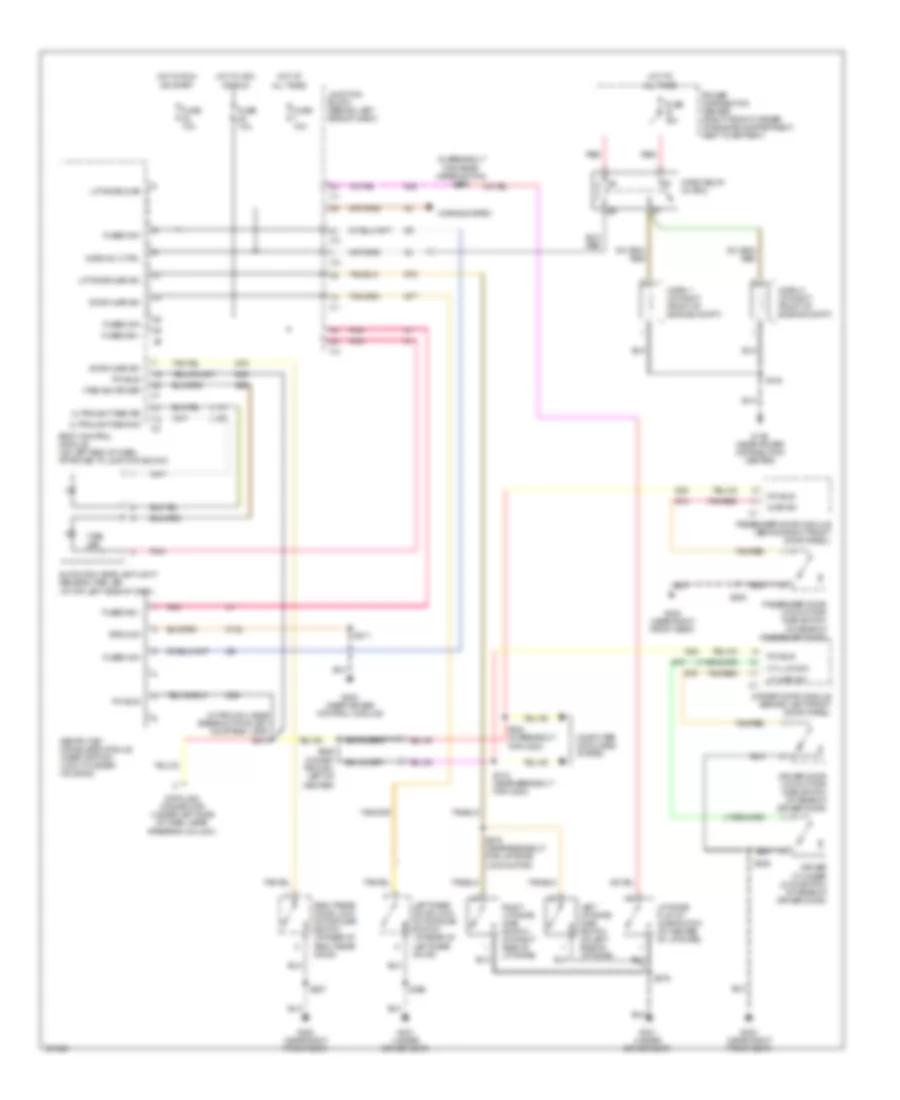
ANTI-THEFT
Anti-theft Wiring Diagram for Jeep Grand Cherokee Limited 2004
List of elements for Anti-theft Wiring Diagram for Jeep Grand Cherokee Limited 2004:
- (in breakout for rear wiper motor) s379
- (in trough, near breakout for left courtesy lamp) s210
- Ajar sw
- Automatic headlamp light sensor/vtss led (at top left side of dash)
- Body control module (on left end of dash, attached to junction block)
- Computer data lines system
- Cyl lck sw
- D25
- Data link connector (under left side of dash, near steering column)
- Door ajar sw
- Driver cylinder lock switch (at rear of driver door)
- Driver door lock motor/ ajar switch (at rear of driver door)
- Driver door module (behind left front door panel)
- Fuse 10a
- Fuse 15a
- Fused b(+)
- Fused ign
- G108 (near power distribution center)
- G200 (near air bag control module)
- G300 (near right front seat)
- G301 (under driver seat)
- G69
- G73
- G74
- G75
- G76
- G77
- G78
- G80
- Ground
- Horn 1 (at right front of engine compt)
- Horn 2 (at right front of engine compt)
- Horn relay (in pdc)
- Horn rly ctrl
- Horns system
- Hot at all times
- Hot in acc or run
- Hot in run or start
- Junction block (behind left side of dash)
- L109
- L110
- Left liftgate ajar switch (at left side of liftgate)
- Left rear door lock motor/ajar switch (at rear of left rear door)
- Lf ajar sw
- Liftgate ajar
- Liftgate ajar sw
- Liftgate flip-up ajar switch (at center of liftgate)
- Passenger door lock motor/ ajar switch (at rear of passenger door)
- Passenger door module (behind right front door panel)
- Pci bus
- Pnk
- Power distribution center (right front corner of engine compartment, next to battery)
- Red
- Right liftgate ajar switch (at right side of liftgate)
- Right rear door lock motor/ajar switch (at rear of right rear door)
- S132
- S211
- S226 (in dash trough, left of center)
- S312 (near breakout for c200)
- S324 (in breakout for c200)
- S336
- S338
- S356
- S357
- S376
- S378 (near breakout for liftgate lock motor)
- Sentry key immoblizer module (near ignition lock cylinder housing)
- Tan/red
- Ultralight sen re
- Ultralight sen sig
- Vtss ind driver
- Vtss led
- Z132
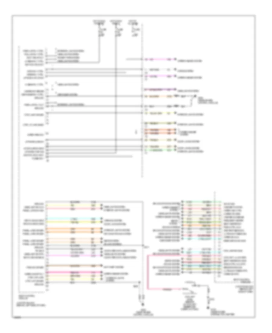
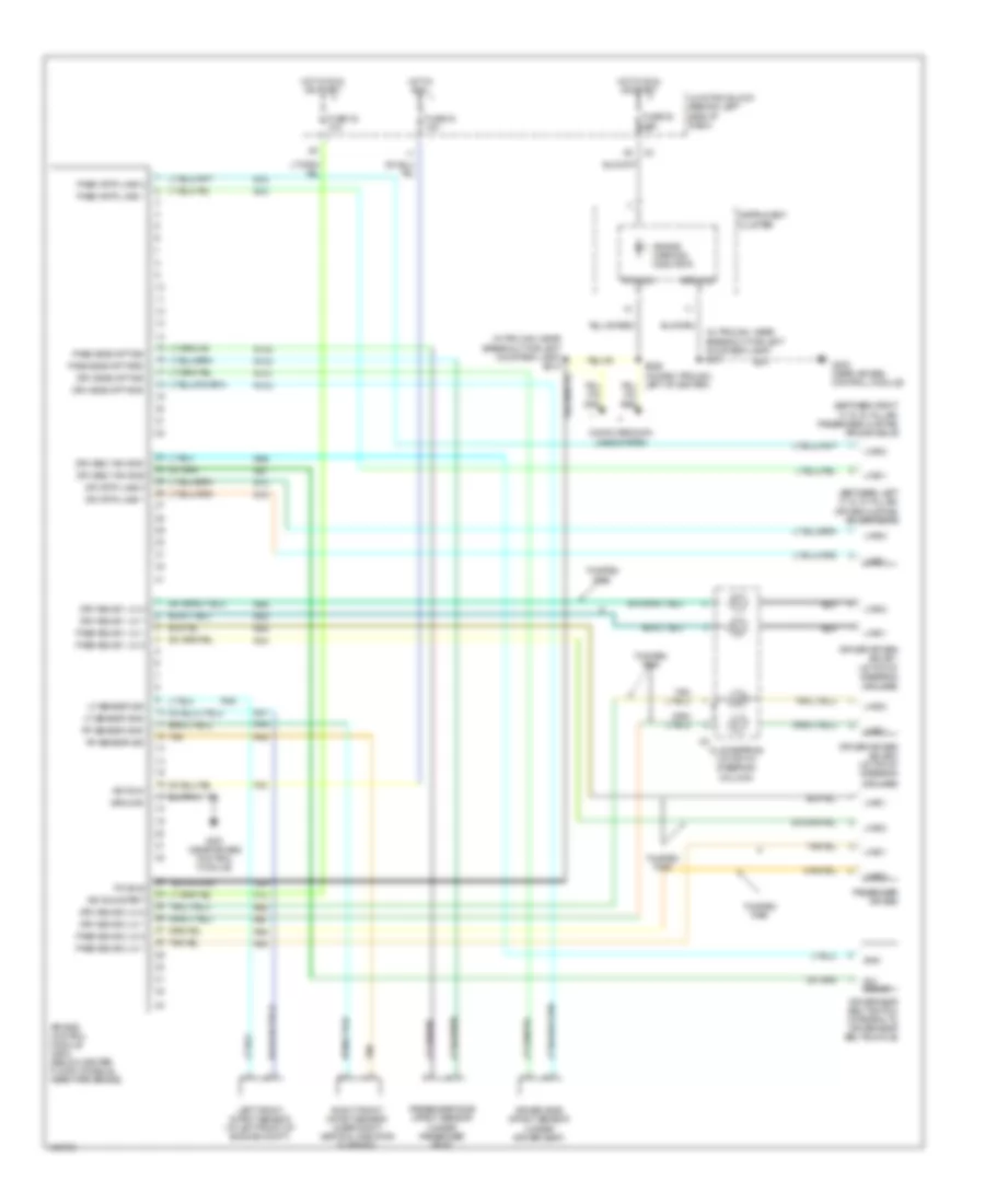
BODY CONTROL MODULES
Body Control Modules Wiring Diagram for Jeep Grand Cherokee Limited 2004
List of elements for Body Control Modules Wiring Diagram for Jeep Grand Cherokee Limited 2004:
- A/c sw sig
- Accy delay rly
- Air conditioning system
- Amb temp sens sig
- Anti-theft system
- Bcm flash enable
- Body control module
- C103
- C201
- C81
- Computer data lines system
- Coolant level sensor (in coolant reservoir/ overflow tank)
- Coolant lvl sw sns
- Ctsy lamp driver
- Ctsy lmp driver
- Ctsy lmp load
- Ctsy lp load shed
- D19
- D25
- Defogger rly ctrl
- Defogger system
- Door locks system
- E19
- Exterior lights system
- Fog lamp sw sns
- Fog lmp rly ctrl
- Fuse 10a
- Fused b(+)
- G108 (near power distribution center)
- G18
- G200 (near air bag control module)
- G26
- G31
- G32
- G52
- G69
- G73
- G76
- G77
- G78
- G80
- Ground
- Hazard sw sense
- Headlamp sw mux
- Headlamp sw rtn
- Headlights system
- Hi beam rly ctrl
- Hi beam sw sns
- Horn rly ctrl
- Horns system
- Hot at all times
- Hot in run or acc
- Hot in run or start
- Ignition (run-acc)
- Ignition (run-st)
- Interior lights system
- Junction block (behind left side of dash)
- Key-in ign sw sns
- L109
- L110
- L27
- L40
- L80
- L91
- Liftgate ajar sw
- Liftgate ctsy dis
- Liftgte flip-up sw
- Lo beam rly ctrl
- Lr dr ajar sw sns
- M20
- P132
- P133
- P134
- Panel lmps dim sig
- Panel lmps driver
- Park lmp rly ctrl
- Park lmp rly out
- Pass seat heater
- Pci bus
- Power tops system
- Radio ctrl mux
- Radio ctrl mux rtn
- Rear defog sw sns
- Red
- Rr dr ajar sw sns
- S132
- S205
- S211
- Seat heater sw
- Seat heater sw gnd
- Seats system
- Sensor ground
- Sound system
- Sound systems
- Tan/red
- Ultralight sens rtn
- Ultralight sens sig
- V10
- V11
- V14
- V16
- V48
- V52
- V55
- Vtss ind driver
- Warning system
- Washer pump sw
- Washer sw sense
- Wiper high ctrl
- Wiper on/off rly
- Wiper park sw
- Wiper rly ctrl
- Wiper sw mux
- Wiper sw rtn
- Wiper/washer system
- X10
- X20
- Z132
- Z234
COMPUTER DATA LINES
Computer Data Lines Wiring Diagram for Jeep Grand Cherokee Limited 2004
List of elements for Computer Data Lines Wiring Diagram for Jeep Grand Cherokee Limited 2004:
- (in trough, near breakout for left courtesy lamp) s210
- Adjustable pedals module (except base)
- Air bag control module (below center floor console, near park brake)
- Automatic zone control module
- Body control module (on left end of dash, attached to junction block)
- Compact disc changer (premium)
- Controller anti-lock brake (on left side of engine compt, mounted to hydraulic control unit)
- D19
- D20
- D21
- D25
- D32
- Data link connector (under left side of dash, near steering column)
- Driver door module (behind left front door panel)
- Flash enable
- Fuse 10a
- G103 (at right side of engine)
- Hot at all times
- Instrument cluster
- Junction block (behind left side of dash)
- Passenger door module (behind right front door panel)
- Pci bus
- Pnk
- Pnk/red
- Power amplifier (premium) (under passenger side rear seat cushion)
- Powertrain control module (on right side of firewall)
- Radio
- Rain sensor (w/ autowipe) (at front center overhead)
- S125 (4.7l) (near breakout for powertrain control module)
- S130 (4.7l) (in breakout for coolant level senseor)
- S223 (near breakout for adjustable pedal switch)
- S226 (in dash trough, left of center)
- S312 (near breakout for c200)
- S324 (in breakout for c200)
- S335 (except base)
- Sci receive
- Sci transmit
- Seat module (except base)
- Sentry key immobilizer module (near ignition lock cylinder housing)
- Transmission control module (4.7l) (on right inner fender)
- Vehicle information center
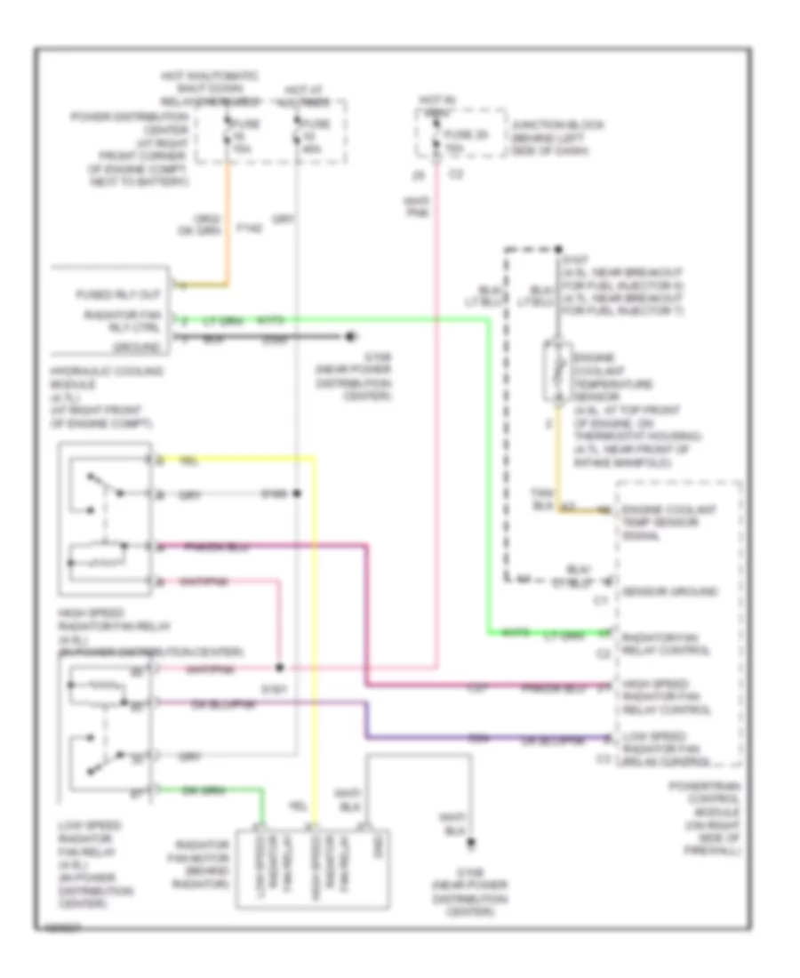
COOLING FAN
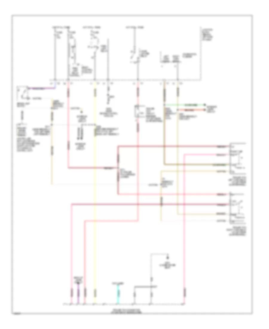
Cooling Fan Wiring Diagram for Jeep Grand Cherokee Limited 2004
List of elements for Cooling Fan Wiring Diagram for Jeep Grand Cherokee Limited 2004:
- C24
- C27
- Engine coolant
- Engine coolant temperature sensor (4.0l: at top front of engine, on thermostat housing) (4.7l: near front of intake manifold)
- F142
- Fan relay
- Fuse 15a
- Fuse 20 10a
- Fuse 40a
- Fused rly out
- G108 (near power distribution center)
- Gnd
- Ground
- High speed
- High speed radiator fan relay (4.0l) (in power distribution center)
- Hot at all times
- Hot in run
- Hot w/automatic shut down relay energized
- Hydraulic cooling module (4.7l) (at right front of engine compt)
- Junction block (behind left side of dash)
- K173
- Low speed
- Low speed radiator fan relay (4.0l) (in power distribution center)
- Power distribution center (at right front corner of engine compt, next to battery)
- Powertrain control module (on right side of firewall)
- Radiator fan motor (behind radiator)
- Radiator fan relay control
- Radiator fan relay control c2
- Radiator fan rly ctrl
- Radiator high speed
- Radiator low speed
- S180
- S181
- Sensor ground
- Temp sensor signal
- Z500
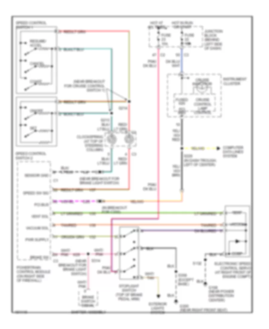
CRUISE CONTROL
Cruise Control Wiring Diagram for Jeep Grand Cherokee Limited 2004
List of elements for Cruise Control Wiring Diagram for Jeep Grand Cherokee Limited 2004:
- (in breakout for c200)
- (near breakout for brake light switch)
- (near breakout for cruise control switch 1)
- Brake sw
- Brake switch signal
- Cancel
- Clockspring (at top of steering column)
- Coast
- Computer data lines system
- Cruise control lamp control
- Cruise indicator
- D25
- Dump
- Electronic speed control servo (at right front of engine compt)
- Exterior lights system
- Fuse 10a
- Fuse 15a
- Fused ign
- G108 (near power distribution center)
- G300 (near right front seat)
- Hot at all times
- Hot in run or start
- Instrument cluster
- Junction block (behind left side of dash)
- K29
- On/off
- Pci bus
- Powertrain control module (on right side of firewall)
- Resume/ accel
- S132
- S214
- S314
- S315
- S324
- S358 (except base)
- Sensor gnd
- Set
- Shifter assembly
- Speed control switch 1
- Speed control switch 2
- Speed sw sig
- Stoplight switch (top of brake pedal arm)
- Tan/red
- V32
- V35
- V36
- V37
- Vacuum
- Vacuum sol
- Vent
- Vent sol
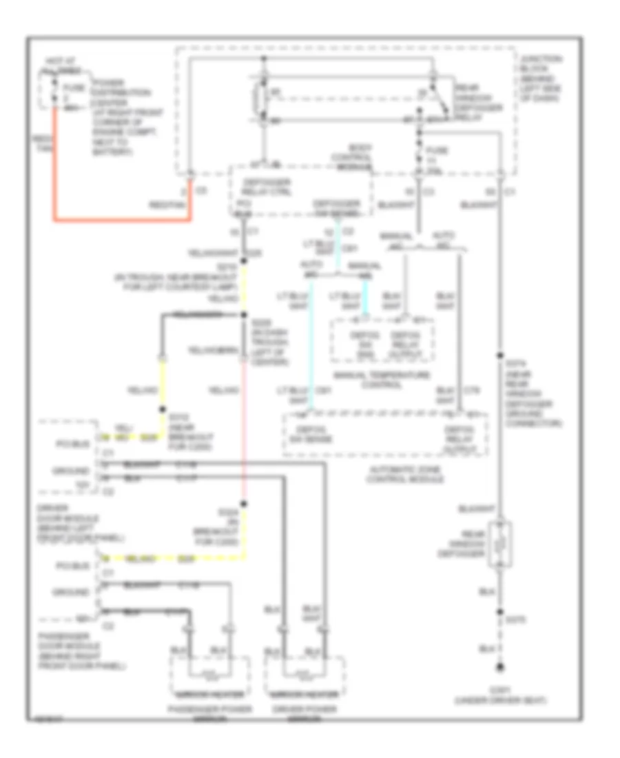
DEFOGGERS
Defoggers Wiring Diagram for Jeep Grand Cherokee Limited 2004
List of elements for Defoggers Wiring Diagram for Jeep Grand Cherokee Limited 2004:
- (near rear window defogger ground connector)
- 12v
- 87a
- Auto a/c
- Automatic zone control module
- Body control module
- C117
- C118
- D25
- Defog relay output
- Defog sw sense
- Defog sw sns
- Defogger relay ctrl
- Defogger sw sense
- Driver door module (behind left front door panel)
- Driver power mirror
- Fuse 10a
- Fuse 40a
- G301 (under driver seat)
- Ground
- Hot at all times
- Junction block (behind left side of dash)
- Manual a/c
- Manual temperature control
- Mirror heater
- Passenger door module (behind right front door panel)
- Passenger power mirror
- Pci bus
- Power distribution center (at right front corner of engine compt, next to battery)
- Rear window defogger
- Rear window defogger relay
- Red/ tan
- Red/tan
- S210 (in trough, near breakout for left courtesy lamp)
- S226 (in dash trough, left of center)
- S312 (near breakout for c200)
- S324 (in breakout for c200)
- S374
- S375
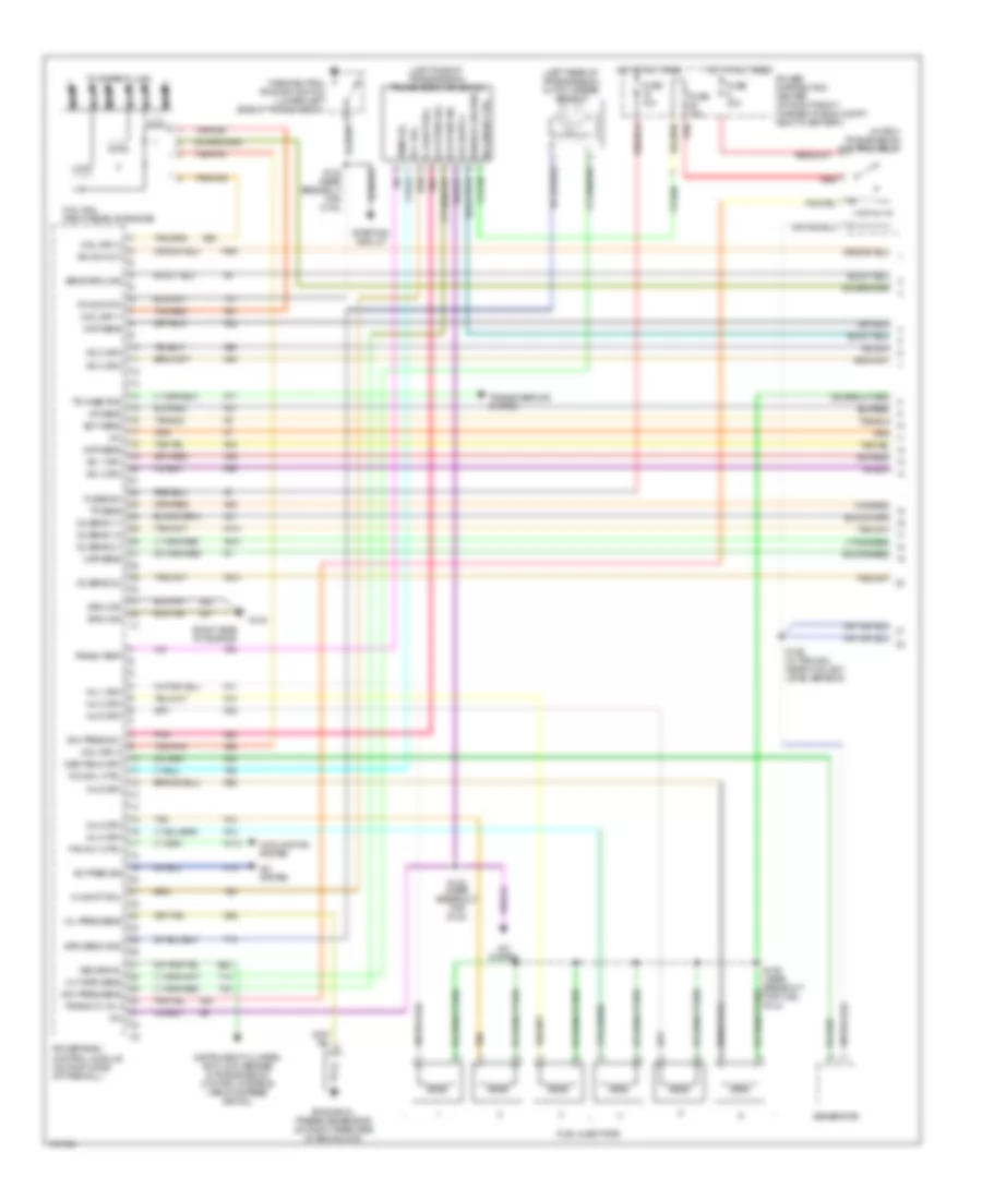
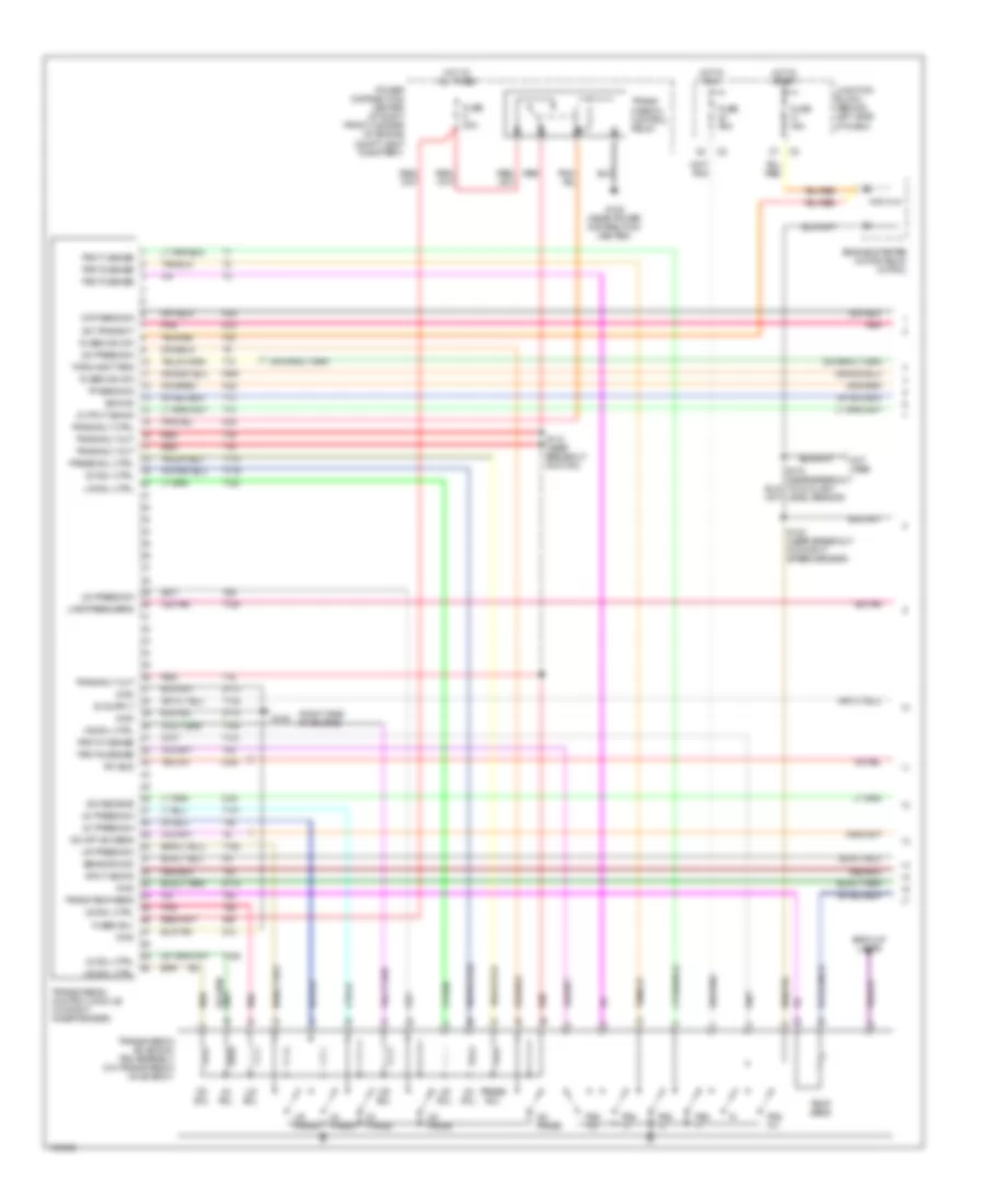
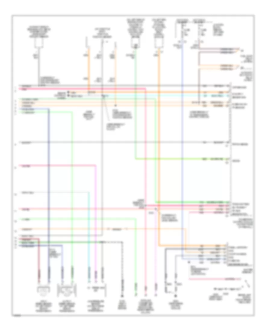
ENGINE PERFORMANCE
4.0L
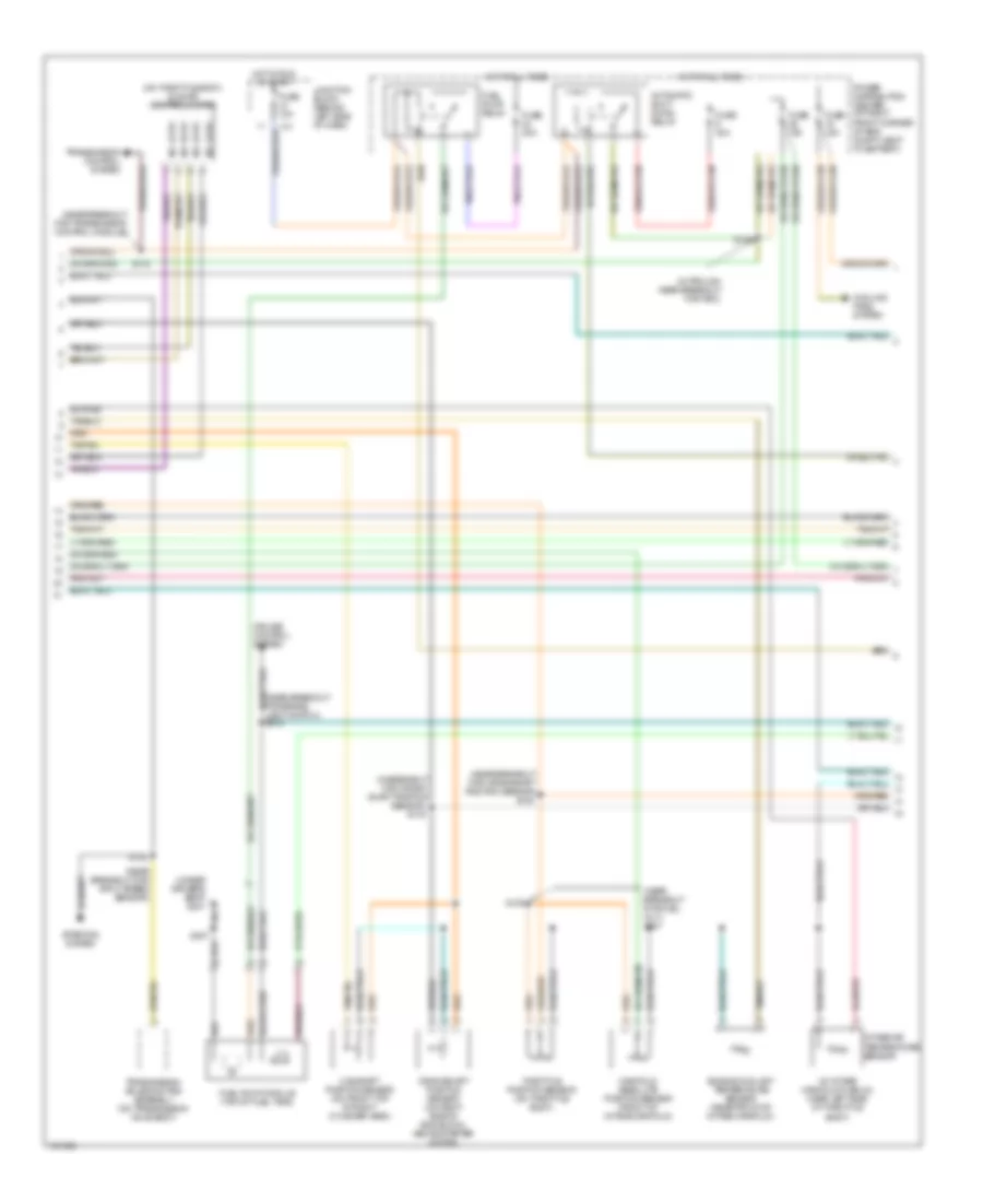
4.0L, Engine Performance Wiring Diagram (1 of 3) for Jeep Grand Cherokee Limited 2004
List of elements for 4.0L, Engine Performance Wiring Diagram (1 of 3) for Jeep Grand Cherokee Limited 2004:
- (in pdc) transmission control relay
- (left rear of transmission) output speed sensor
- (left side of transmission) transmission solenoid
- (right side of engine)
- +5v
- 3-4 shift sol
- A/c pres sig
- A/c system
- B22
- C18
- Ckp sens
- Cmp sens
- Coil drv 1
- Coil drv 2
- Coil drv 3
- Coil rail (right rear of engine)
- Cooling fan system
- Ect sens
- Engine oil pressure sensor (on right rear side of eng block)
- F991
- Fan rly ctrl
- Fuel injectors
- Fuse 10a
- Fuse 15a
- Fuse 30a
- Fused b+
- G103
- G60
- Gen field drv
- Generator
- Gov pres sens
- Gov pres sig
- Gov pres sol
- Ground
- Hot at all times
- Iac 1 drv
- Iac 2 drv
- Iac 3 drv
- Iac 4 drv
- Iat sens
- Ign sw out
- Inj 1 drv
- Inj 2 drv
- Inj 3 drv
- Inj 4 drv
- Inj 5 drv
- Inj 6 drv
- Instrument cluster, anti-lock brakes & transmission control systems (vehicle speed signal)
- K11
- K12
- K13
- K14
- K141
- K173
- K20
- K21
- K22
- K24
- K241
- K30
- K341
- K38
- K39
- K40
- K41
- K44
- K58
- K59
- K60
- K77
- K88
- K91
- K92
- K93
- Map sens
- Nca
- O2 sens 1/1
- O2 sens 1/2
- O2 sens 2/1
- O2 sens 2/2
- Oil pres sens
- Out spd sens
- P/n switch
- Park/neutral position switch (lower left side of transmission)
- Pnk
- Power distribution center (at right front corner of eng compt, next to battery)
- Powertrain control module (on right side of firewall)
- Red
- S102 (near breakout for g104)
- S109 (near breakout for fuel inj 2)
- S122 (near breakout for c103)
- S126 (in trough, near coolant level sensor)
- Sens ground
- Sensor ground
- Solenoid ctrl
- Spd sens gnd
- Starting circuit
- T13
- T14
- T20
- T25
- T41
- T54
- T60
- Tan
- Tan/pnk
- Tan/red
- Tcc sol
- Tcc sol ctrl
- Temp sig
- To spark plugs
- Tp sens
- Tr case pos
- Trans ctl rly
- Trans temp
- Transmissions system
- Vss signal
- Z81
- Z82
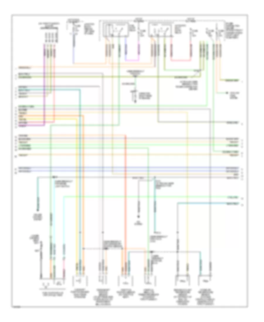
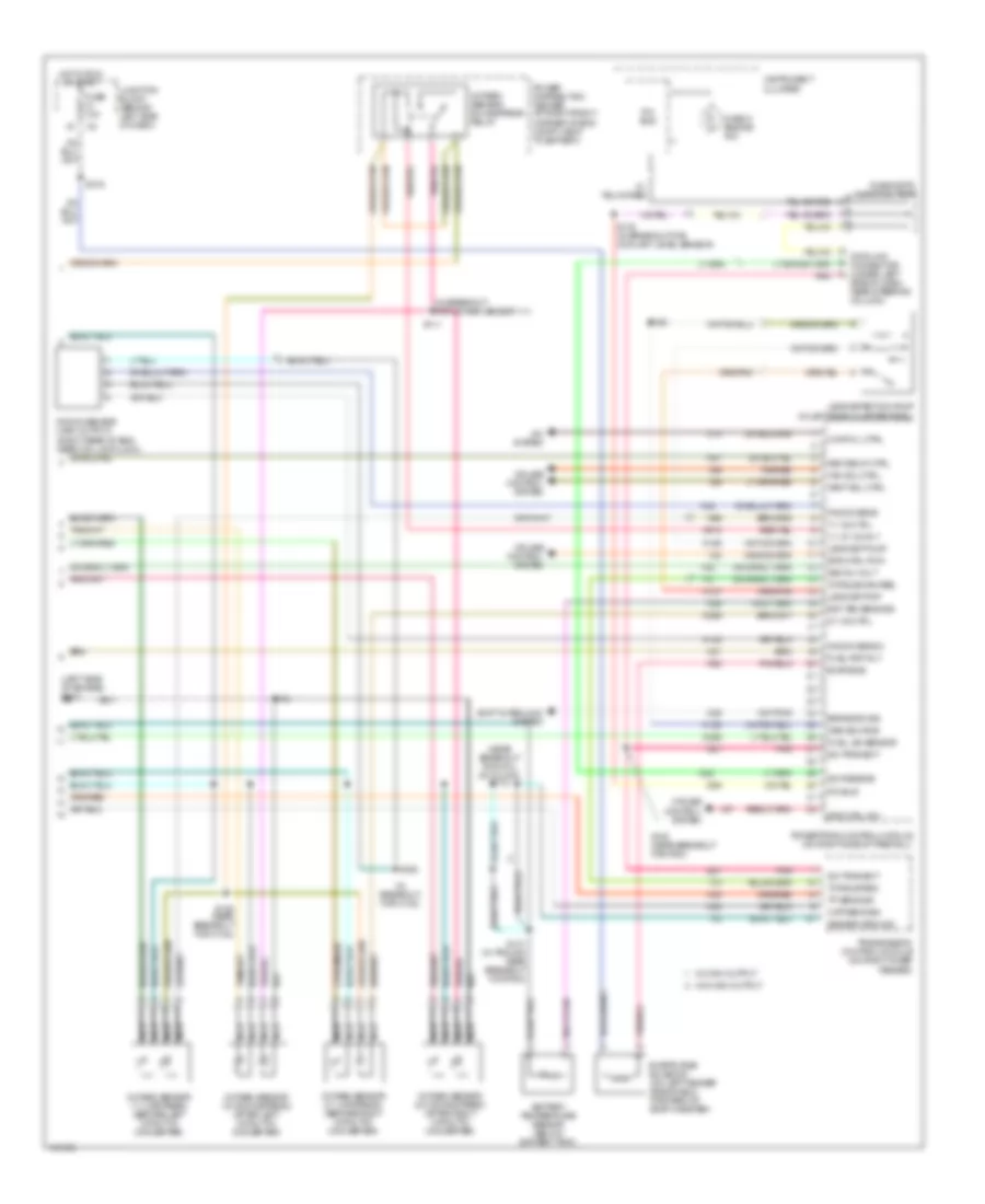
4.0L, Engine Performance Wiring Diagram (2 of 3) for Jeep Grand Cherokee Limited 2004
List of elements for 4.0L, Engine Performance Wiring Diagram (2 of 3) for Jeep Grand Cherokee Limited 2004:
- (in trough near breakout for power distribution center)
- (near breakout for brake light switch)
- (near breakout for c103 & c104)
- (near breakout for crankshaft position sensor) s105
- (near breakout for fuel inj 6)
- (near breakout for g104) s123
- (on throttle body) idle air control motor
- (under driver's seat) g301
- A/c system
- Automatic shut down relay
- Camshaft position sensor (right rear of engine)
- Capacitor (right rear of engine)
- Cooling fans system
- Crankshaft position sensor (at left rear side of eng block, on transmission bellhousing)
- Cruise control system
- Engine coolant temperature sensor (at top front of eng, on thermostat housing)
- Fuel pump module (top of fuel tank)
- Fuel pump relay
- Fuse 10a
- Fuse 15a
- Fuse 20a
- Fuse 30a
- Hot at all times
- Hot in run or start
- Intake air temperature sensor (in intake manifold plenum, near front of throttle body)
- Junction block (behind left side of dash)
- Manifold absolute pressure sensor (on side of throttle body)
- Nca
- No 1 drv
- No 2 drv
- No 3 drv
- No 4 drv
- Power distribution center (at right front corner of eng compt, next to battery)
- S107
- S112
- S128
- S131 (in trough near breakout for pdc)
- S315
- Throttle position sensor (on throttle body)
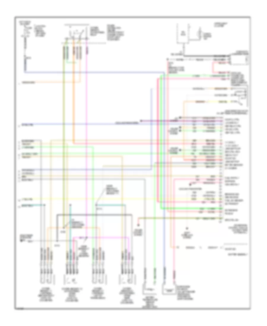
4.0L, Engine Performance Wiring Diagram (3 of 3) for Jeep Grand Cherokee Limited 2004
List of elements for 4.0L, Engine Performance Wiring Diagram (3 of 3) for Jeep Grand Cherokee Limited 2004:
- (in breakout for oxygen sensors)
- (near breakout for oxygen sensor 1/1)
- (near breakout for oxygen sensors)
- (on left fender side shield, forward of evap canister)
- (right rear of engine) g104
- (under left side of dash, near steering column)
- 1/1 2/1 o2 rly
- 1/1 o2 rly
- 2/1 o2 sens
- A/c system
- Asd relay ctrl
- Asd rly out
- Bat tem sens sig
- Battery temperature sensor (below battery tray)
- Brake sw sig
- C13
- C24
- C27
- Check engine ind
- Comp cl ctrl
- Cooling fans system
- Cruise control system
- D21
- D25
- D32
- Data link connector
- Diagnostic junction port
- Evap emis
- Evap/purge solenoid
- F42
- Fuel lev sensor
- Fuel pmp rly
- Fuse 10a
- Gen source
- High spd rly
- Hot in run or start
- Instrument cluster
- Junction block (behind left side of dash)
- K106
- K107
- K125
- K226
- K25
- K29
- K299
- K31
- K51
- K512
- K52
- K99
- Leak det pmp
- Leak det pump
- Leak detection pump (in left rear quarterpanel)
- Low spd rly
- Nca
- Od off sw
- Oxygen sensor 1/1 (upstream) (before front catalytic converter)
- Oxygen sensor 1/2 (downstream) (after front catalytic converter)
- Oxygen sensor 2/1 (upstream) (left of transmission)
- Oxygen sensor 2/2 (downstream) (after rear catalytic converter)
- Oxygen sensor downstream relay
- Pci bus
- Pnk
- Power distribution center (at right front corner of eng compt, next to battery)
- Powertrain control module (on right side of firewall)
- S104
- S106
- S110
- S111
- S130 (in breakout for coolant level sensor)
- Sci receive
- Sci transmit
- Shift interlock system
- Shifter assembly
- Spd ctrl pow
- Spd ctrl sw
- Tan/red
- V32
- V35
- V36
- V37
- Vac sol ctrl
- Vent sol ctrl
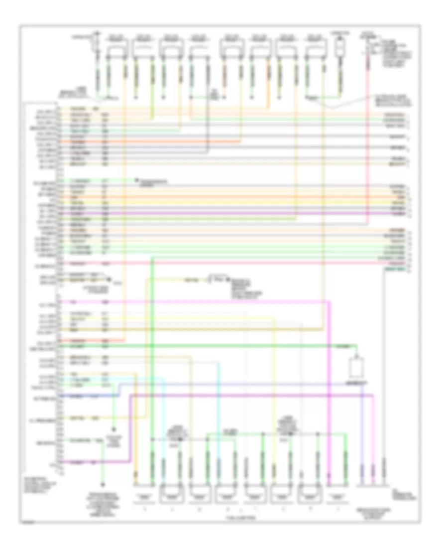
4.7L
4.7L, Engine Performance Wiring Diagram (1 of 3) for Jeep Grand Cherokee Limited 2004
List of elements for 4.7L, Engine Performance Wiring Diagram (1 of 3) for Jeep Grand Cherokee Limited 2004:
- (at right side of engine)
- (behind right side of radiator support)
- (in trough, near breakout for idle air control motor)
- (near breakout for coil on plug 4)
- (near breakout for coil on plug 6)
- (near breakout for idle air control motor)
- +5v
- A/c pres sig
- A/c pressure transducer
- B22
- C18
- Capacitor
- Ckp sens
- Cmp sens
- Coil drv 1
- Coil drv 2
- Coil drv 3
- Coil drv 4
- Coil drv 5
- Coil drv 6
- Coil drv 7
- Coil drv 8
- Coil on plug 1
- Coil on plug 2
- Coil on plug 3
- Coil on plug 4
- Coil on plug 5
- Coil on plug 6
- Coil on plug 7
- Coil on plug 8
- Cooling fans system
- Ect sens
- Engine oil pressure sensor (right rear side of eng block)
- F991
- Fan rly ctrl
- Fuel injectors
- Fuse 10a
- Fused b+
- G103
- G60
- Gen field drv
- Generator
- Ground
- Hot at all times
- Iac 1 drv
- Iac 2 drv
- Iac 3 drv
- Iac 4 drv
- Iat sens
- Ign sw out
- Inj 1 drv
- Inj 2 drv
- Inj 3 drv
- Inj 4 drv
- Inj 5 drv
- Inj 6 drv
- Inj 7 drv
- Inj 8 drv
- K11
- K12
- K13
- K14
- K141
- K173
- K20
- K21
- K22
- K24
- K241
- K26
- K28
- K341
- K38
- K39
- K40
- K41
- K44
- K58
- K59
- K60
- K77
- K91
- K92
- K93
- K94
- K95
- K96
- K97
- K98
- Map sens
- Nca
- O2 sens 1/1
- O2 sens 1/2
- O2 sens 2/1
- O2 sens 2/2
- Oil pres sens
- P/n switch
- Power distribution center (at right front corner of eng compt, next to battery)
- Powertrain control module (on right side of firewall)
- S109
- S118
- S121
- S124
- Sens ground
- T41
- Tan
- Tan/pnk
- Tan/red
- Tp sens
- Tr case pos
- Transmissions system
- Transmissions, anti-lock brakes & instrument cluster systems (vehicle speed signal)
- Vss signal
- Z81
- Z82
4.7L, Engine Performance Wiring Diagram (2 of 3) for Jeep Grand Cherokee Limited 2004
List of elements for 4.7L, Engine Performance Wiring Diagram (2 of 3) for Jeep Grand Cherokee Limited 2004:
- (in breakout for crank- shaft position sensor) s119
- (in intake manifold plenum, near left side of throttle body)
- (in trough near breakout for pdc)
- (near breakout for brake light switch) s315
- (near breakout for crankshaft position sensor) s120
- (near breakout for fuel inj 7) s107
- (near breakout for input speed sensor)
- (near breakout for transmission control module)
- (on throttle body) idle air control motor
- (under driver's seat) g301
- Automatic shut down relay
- Camshaft position sensor (on front top of right cylinder head)
- Cooling fans system
- Crankshaft position sensor (on right side of eng block, above starter motor)
- Cruise control system
- Engine coolant temperature sensor (near front of intake manifold)
- Fuel pump module (top of fuel tank)
- Fuel pump relay
- Fuse 10a
- Fuse 15a
- Fuse 20a
- Fuse 30a
- Hot at all times
- Hot in run or start
- Intake air temperature sensor
- Junction block (behind left side of dash)
- Manifold absolute position sensor (front of intake manifold)
- No 1 drv
- No 2 drv
- No 3 drv
- No 4 drv
- Power distribution center (at right front corner of eng compt, next to battery)
- S105
- S116
- S122
- S128
- Starting system
- Throttle position sensor (on throttle body)
- Transmission control system
- Transmission solenoid/trs assembly (on transmission valve body)
4.7L, Engine Performance Wiring Diagram (3 of 3) for Jeep Grand Cherokee Limited 2004
List of elements for 4.7L, Engine Performance Wiring Diagram (3 of 3) for Jeep Grand Cherokee Limited 2004:
- (in breakout for c102)
- (in breakout for oxygen sensor 1/1)
- (left side of engine) g104
- (near breakout for c102)
- (near breakout for coil on plug 8) s112
- 1/1 2/1 o2 rly
- 1/1 o2 ctrl
- 2/1 o2 ctrl
- A/c system
- Asd relay ctrl
- Asd rly out
- Bat tem sens sig
- Battery temperature sensor (below battery tray)
- Brake sw sig
- C13
- Check engine ind
- Ckp sens sig
- Comp cl ctrl
- Cruise control system
- D21
- D25
- D32
- Data link connector (under left
- Diagnostic junction port
- Evap emis
- Evap/purge solenoid (on left fender side shield, forward of evap canister)
- F42
- Fuel lev sensor
- Fuel pmp rly
- Fuse 10a
- Gen source
- Hot in run or start
- Instrument cluster
- Junction block (behind left side of dash)
- K106
- K107
- K125
- K142
- K22
- K226
- K24
- K25
- K29
- K299
- K31
- K42
- K51
- K512
- K52
- K99
- Knock sens
- Knock sens 2
- Knock sensor (high output) (right rear of eng, near coil on plug 8)
- Leak det pmp
- Leak det pump
- Leak detection pump (in left rear quarterpanel)
- Nca
- Oxygen sensor 1/1 (upstream) (before left catalytic converter)
- Oxygen sensor 1/2 (downstream) (after left catalytic converter)
- Oxygen sensor 2/1 (upstream) (before right catalytic converter)
- Oxygen sensor 2/2 (downstream) (after right catalytic converter)
- Oxygen sensor downstream relay
- Pci bus
- Pnk
- Power distribution center (at right front corner of eng compt, next to battery)
- Powertrain control module (on right side of firewall)
- S104
- S106
- S111
- S125 (near breakout for pcm)
- S126
- S130 (in breakout for coolant level sensor)
- S131 (in trough near breakout for pdc)
- S160
- S316
- Sci receive
- Sci transmit
- Sensor ground
- Shift interlock system
- Side of dash, near steering column)
- Spd ctrl pow
- Spd ctrl sw
- T10
- Tan/red
- Torque man req
- Torque req
- Tp sens sig
- Transmission control module (on right inner fender)
- V32
- V35
- V36
- V37
- Vac sol ctrl
- Vent sol ctrl
- W/ high output
- W/o high output
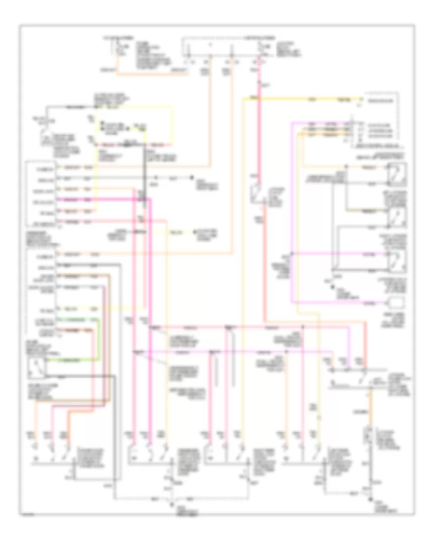
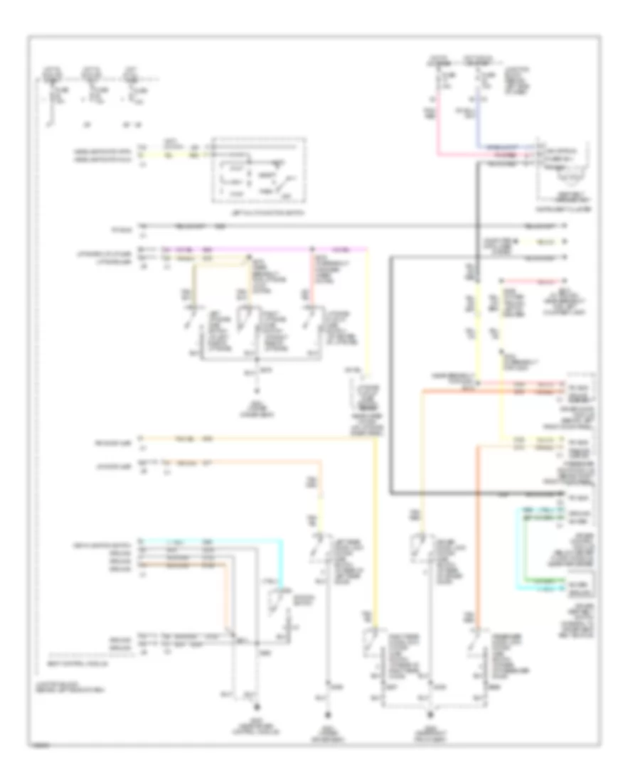
EXTERIOR LIGHTS
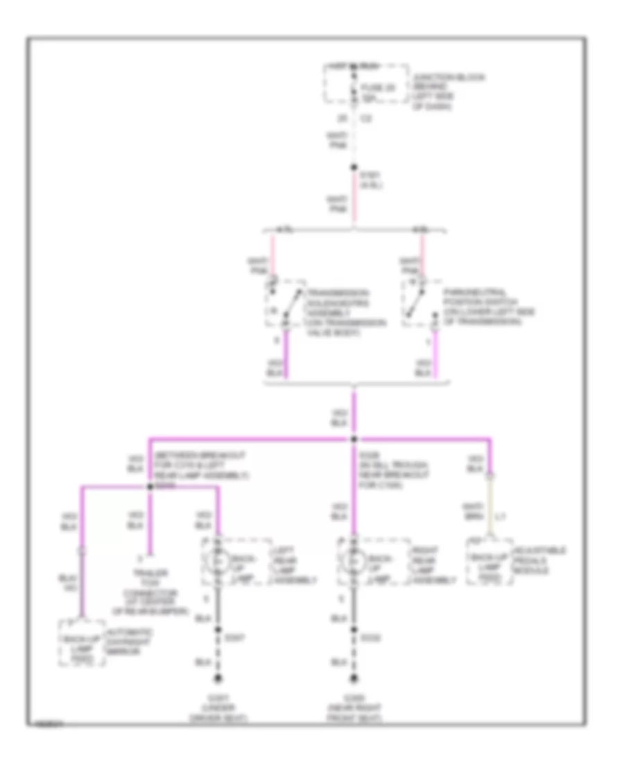
Back-up Lamps Wiring Diagram for Jeep Grand Cherokee Limited 2004
List of elements for Back-up Lamps Wiring Diagram for Jeep Grand Cherokee Limited 2004:
- (between breakout for c310 & left rear lamp assembly) s310
- 4.0l
- 4.7l
- Adjustable pedals module
- Automatic day/night mirror
- Back- up lamp
- Back-up lamp feed
- Fuse 20 10a
- G300 (near right front seat)
- G301 (under driver seat)
- Hot in run
- Junction block (behind left side of dash)
- Left rear lamp assembly
- Park/neutral position switch (on lower left side of transmission)
- Right rear lamp assembly
- S181 (4.0l)
- S307
- S328 (in sill trough, near breakout for c106)
- S332
- Trailer tow connector (at center of rear bumper)
- Transmission solenoid/trs assembly (on transmission valve body)
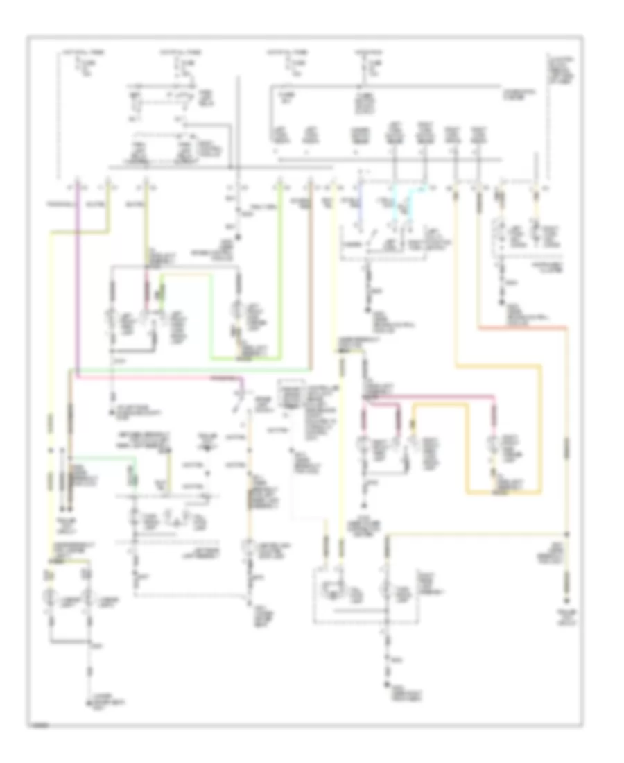
Exterior Lamps Wiring Diagram for Jeep Grand Cherokee Limited 2004
List of elements for Exterior Lamps Wiring Diagram for Jeep Grand Cherokee Limited 2004:
- (at left side of engine compt) g106
- (between breakout for c310 & left rear lamp assembly) s309
- (in headlight assembly) s154
- (in headlight assembly) s155
- (in headlight assembly) s156
- (near breakout for c106) s326
- (near breakout for license lamp 1) s380
- (under driver seat) g301
- 87a
- B(+)
- Body control module
- Brake lamp switch
- Center high mounted stop lamp
- Combination flasher
- Controller anti-lock brake (on left side engine compt, mounted to hydraulic control unit)
- Fuse 10a
- Fuse 15a
- Fused
- Fused ignition switch output
- G108 (near power distribution center)
- G200 (near air bag control module)
- G300 (near right front seat)
- G301 (under driver seat)
- Hazard
- Hazard switch sense
- Headlight assembly) s153
- Hot at all times
- Hot in run
- Instrument cluster
- Junction block (behind left side of dash)
- Left front park lamp
- Left front park/ turn signal lamp
- Left front side marker lamp
- Left multi- function switch
- Left rear lamp assembly
- Left turn
- Left turn indi- cator
- Left turn signal
- Left turn switch sense
- License lamp 1
- License lamp 2
- Park lamp relay
- Park lamp relay control
- Park lamp relay output
- Primary brake switch signal
- Right front park lamp
- Right front park/ turn signal lamp
- Right front side marker lamp
- Right rear lamp assembly
- Right turn
- Right turn indi- cator
- Right turn signal
- Right turn switch sense
- S151
- S152
- S203
- S205
- S306 (near breakout for c310)
- S307
- S311 (near breakout for left rear lamp assembly)
- S313 (near breakout for c302)
- S327 (near breakout for c307)
- S332
- S375
- S381
- Tail/ stop lamp
- Tan
- Tan/
- Trailer tow circuit
- Turn signal lamp
Trailer Tow Wiring Diagram for Jeep Grand Cherokee Limited 2004
List of elements for Trailer Tow Wiring Diagram for Jeep Grand Cherokee Limited 2004:
- (in
- (near breakout for c302) s313
- (not used)
- 15a
- 87a
- Back-up lamps circuit
- Body control module
- Brake lamp switch
- Breakout for c310) s372
- Cigar lighter relay
- Combination flasher
- Controller anti-lock brake (on left side engine compt, mounted to hydraulic control unit)
- Exterior lamps circuit
- Fuse 15a
- Fuse 30a
- G200 (near air bag control module)
- G301 (under driver seat)
- Hot at all times
- Junction block (behind left side of dash)
- Left turn signal
- Park lamp relay
- Park lamp relay control
- Primary brake switch signal
- Red/tan
- Right turn signal
- S205
- S306 (near breakout for c310)
- S307
- S309 (between breakout for c310 & left rear lamp assembly)
- S311 (near breakout for left rear lamp assembly)
- S327 (near breakout for c307)
- S371 (in trailer tow harness jumper)
- Trailer tow circuit breaker (at left rear quarterpanel)
- Trailer tow connector (at center of rear bumper)
- Trailer tow left turn relay (at left rear quarterpanel)
- Trailer tow right turn relay (at left rear quarterpanel)
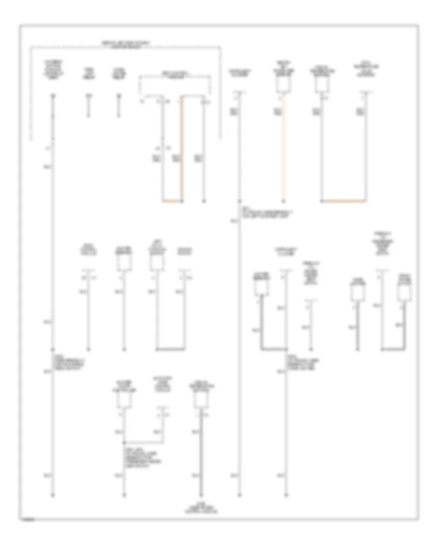
GROUND DISTRIBUTION
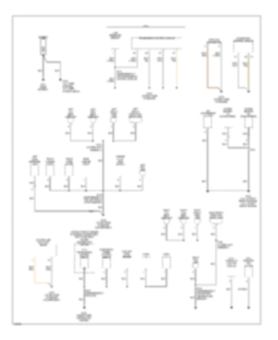
Ground Distribution Wiring Diagram (1 of 4) for Jeep Grand Cherokee Limited 2004
List of elements for Ground Distribution Wiring Diagram (1 of 4) for Jeep Grand Cherokee Limited 2004:
- (4.0l) radiator fan motor
- (4.7l)
- (4.7l) hydraulic cooling module
- (4.7l) transmission control relay
- (at right front corner of engine compartment, next to battery)
- A/c compressor clutch
- Battery
- Controller anti-lock brake
- Coolant level sensor
- Data link connector
- Electronic speed control servo
- Front washer pump
- Front wiper motor
- G100 (4.0l: near starter) (4.7l: near intake plenum)
- G101 (near battery)
- G102 (at right side of engine)
- G103 (at right side of engine)
- G104 (4.0l: at right rear of engine) (4.7l: at left side of engine)
- G106 (at left side of engine compartment)
- G107 (at left side of engine compartment)
- G108 (near power distribution center)
- Horn
- Left fog lamp
- Left front park lamp
- Left front park/turn signal lamp
- Left high beam headlamp
- Left low beam headlamp
- Left side repeater lamp
- Line pressure sensor
- Nca
- Oxygen sensor 1/2 (downstream)
- Oxygen sensor 2/2 (downstream)
- Power distribution center
- Powertrain control module
- Rear washer pump
- Right fog lamp
- Right front park lamp
- Right front park/turn signal lamp
- Right high beam headlamp
- Right low beam headlamp
- S104
- S114 (near breakout for transmission control module)
- S132 (near breakout for g108)
- S133 (near breakout for battery temperature sensor)
- S134 (near breakout for left front impact sensor)
- S151 (in headlight assembly)
- S152 (in headlight assembly)
- Transmission control module
- Washer fluid level switch
Ground Distribution Wiring Diagram (2 of 4) for Jeep Grand Cherokee Limited 2004
List of elements for Ground Distribution Wiring Diagram (2 of 4) for Jeep Grand Cherokee Limited 2004:
- (base)
- (midline/premium) 1
- (midline/premium) driver lumbar switch
- (premium) seat module
- 12 c2
- Adjustable pedals module
- Automatic day/night
- Base
- Center high mounted stop lamp
- Driver power seat switch
- Driver rear power window switch
- Except base
- Except heated seat
- Fuel pump module
- G301 (under driver seat)
- Heated seat
- Left liftgate ajar switch
- Left rear door lock motor/ ajar switch
- Left rear lamp assembly
- License lamp 1
- License lamp 2
- Liftgate flip-up ajar switch
- Liftgate flip-up release solenoid
- Mirror
- Rain sensor
- Rear window defogger
- Rear wiper motor
- Right liftgate ajar switch
- S300 (near breakout for g304)
- S307 (near breakout for c310)
- S345 (near breakout for c309)
- S355 (near breakout for c304 & c306)
- S356 (in breakout for left rear door lock motor/ajar switch)
- S375 (near rear window defogger ground connector)
- S376 (near breakout for liftgate flip-up ajar switch)
- S381 (in breakout for c312)
- Sun roof control module
- Sun roof motor
- Sun roof switch
- Trailer tow connector
- Vehicle vehicle information center center
- W/ sun roof
- W/o sun roof
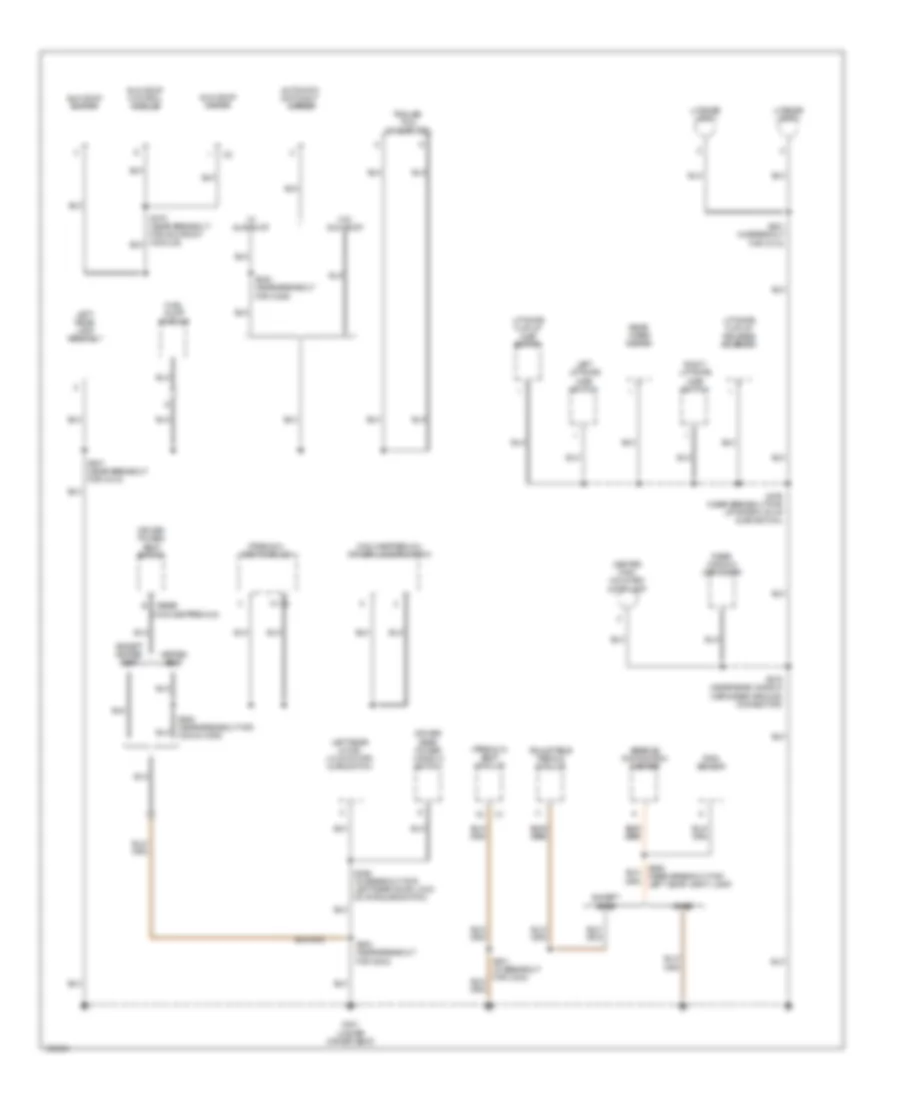
Ground Distribution Wiring Diagram (3 of 4) for Jeep Grand Cherokee Limited 2004
List of elements for Ground Distribution Wiring Diagram (3 of 4) for Jeep Grand Cherokee Limited 2004:
- (except base) (base)
- Adjustable pedals module
- Air bag control module
- Base
- Brake lamp switch
- Driver cylinder lock switch
- Driver door lock motor/ ajar switch
- Driver door module
- Except base
- G201 (near air bag control module)
- G300 (near right front seat)
- Motor)
- Motor/ajar switch)
- Passenger door lock motor/ ajar switch
- Passenger door module
- Passenger lumbar switch
- Passenger power seat switch
- Passenger rear power window switch
- Power amplifier
- Radio
- Rear power outlet
- Right rear door lock motor/ ajar switch
- Right rear lamp assembly
- S224 (at right center of dash)
- S329 (in sill trough, near breakout for c106)
- S330 (near breakout for g300)
- S331 (in sill trough, near breakout for c303)
- S332 (in sill trough, near breakout for c303)
- S341 (near breakout for c306)
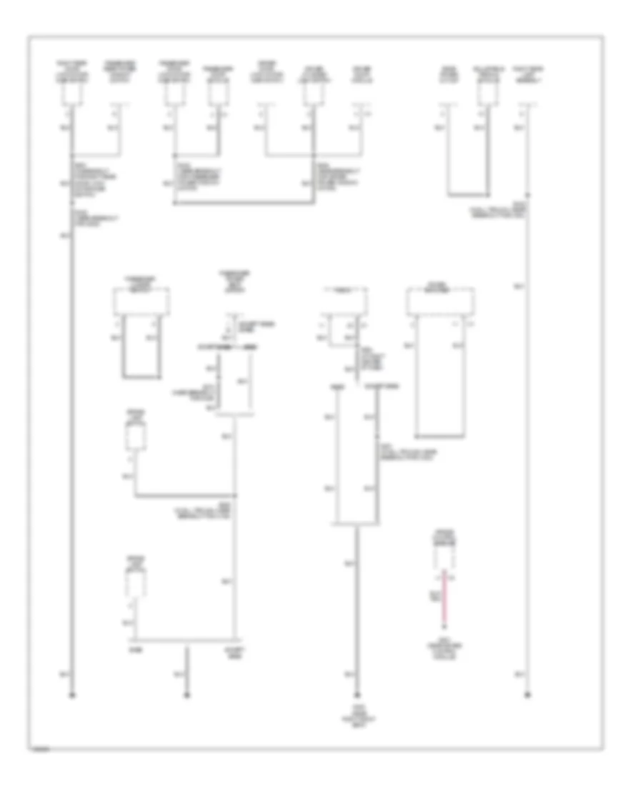
Ground Distribution Wiring Diagram (4 of 4) for Jeep Grand Cherokee Limited 2004
List of elements for Ground Distribution Wiring Diagram (4 of 4) for Jeep Grand Cherokee Limited 2004:
- (behind left side of dash) junction block
- (mtc) temperature valve actuator
- (premium 1/3) driver heated seat switch
- (premium 1/3) passenger heated seat switch
- 14 c1
- 2 c1
- 87a
- Automatic zone control module
- Blower motor controller
- Body control module
- Cigar lighter
- Cigar lighter relay
- Front power outlet
- G200 (near air bag control module)
- Ignition switch
- Instrument cluster
- Left multi- function switch
- Low beam/ daytime running lamp relay (drl)
- Manual temperature control
- Park lamp relay
- S201 (azc) (in trough, near breakout for passenger heated seat switch)
- S203 (in trough, near breakout for cigar lighter)
- S205 (near breakout for adjustable pedal switch)
- S211 (in trough, near breakout for left courtesy lamp)
- Sentry key immobilizer module
- Shifter assembly
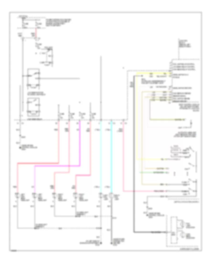
HEADLIGHTS
Headlights Wiring Diagram, with DRL for Jeep Grand Cherokee Limited 2004
List of elements for Headlights Wiring Diagram, with DRL for Jeep Grand Cherokee Limited 2004:
- (at left side of engine compartment) g106
- (in headlight assembly) s151
- (in headlight assembly) s152
- (near air bag control module) g200
- (near power distribution center) g108
- 87a
- Auto
- Automatic headlamp light sensor/vtss lead (at top left side of dash)
- Body control module (on left end of dash, attached to junction block)
- D25
- Flash
- Fog
- Fog lamp indicator
- Fog lamp relay
- Fog lamp relay control
- Fog lamp sw sense
- Fuse 10a
- Fuse 15a
- Fuse 50a
- G52
- Head
- Headlamp sw mux
- Headlamp sw return
- High
- High beam indicator
- High beam relay
- High beam relay control
- High beam sw sense
- Hot at all times
- Instrument cluster
- Junction block (behind left side of dash)
- L109
- L110
- L27
- L40
- L80
- Left fog lamp
- Left high beam headlamp
- Left low beam headlamp
- Left multi-function switch
- Low beam relay control
- Low beam/daytime running lamp relay
- Off
- Park
- Pci bus
- Power distribution center (at right front corner of engine compartment, next to battery)
- Red
- Right fog lamp
- Right high beam headlamp
- Right low beam headlamp
- S133
- S134
- S205
- S210 (in trough, near breakout for left courtesy lamp)
- Sensor return
- Sensor signal
Headlights Wiring Diagram, without DRL for Jeep Grand Cherokee Limited 2004
List of elements for Headlights Wiring Diagram, without DRL for Jeep Grand Cherokee Limited 2004:
- (at left side of engine compartment) g106
- (in headlight assembly) s151
- (in headlight assembly) s152
- (near air bag control module) g200
- (near power distribution center) g108
- Auto
- Automatic headlamp light sensor/vtss lead (at top left side of dash)
- Body control module (on left end of dash, attached to junction block)
- D25
- Flash
- Fog
- Fog lamp indicator
- Fog lamp relay
- Fog lamp relay control
- Fog lamp sw sense
- Fuse 10a
- Fuse 15a
- Fuse 50a
- G52
- Head
- Headlamp sw mux
- Headlamp sw return
- High
- High beam indicator
- High beam relay
- High beam relay control
- High beam sw sense
- Hot at all times
- Instrument cluster
- Junction block (behind left side of dash)
- L109
- L110
- L27
- L40
- L80
- Left fog lamp
- Left high beam headlamp
- Left low beam headlamp
- Left multi-function switch
- Low beam relay (except drl)
- Low beam relay control
- Off
- Park
- Pci bus
- Power distribution center (at right front corner of engine compt, next to battery)
- Red
- Right fog lamp
- Right high beam headlamp
- Right low beam headlamp
- S133
- S134
- S205
- S210 (in trough, near breakout for left courtesy lamp)
- Sensor return
- Sensor signal
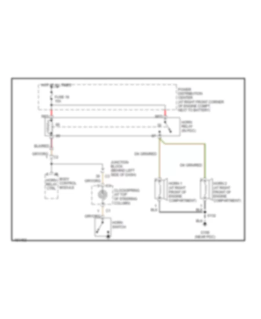
HORN
Horn Wiring Diagram for Jeep Grand Cherokee Limited 2004
List of elements for Horn Wiring Diagram for Jeep Grand Cherokee Limited 2004:
- Body control module
- Clockspring (at top of steering column)
- Fuse 18 15a
- G108 (near pdc)
- Horn 1 (at right front of engine compartment)
- Horn 2 (at right front of engine compartment)
- Horn relay (in pdc)
- Horn relay ctrl
- Horn switch
- Hot at all times
- Junction block (behind left side of dash)
- Power distribution center (at right front corner of engine compt, next to battery)
- Red
- S132
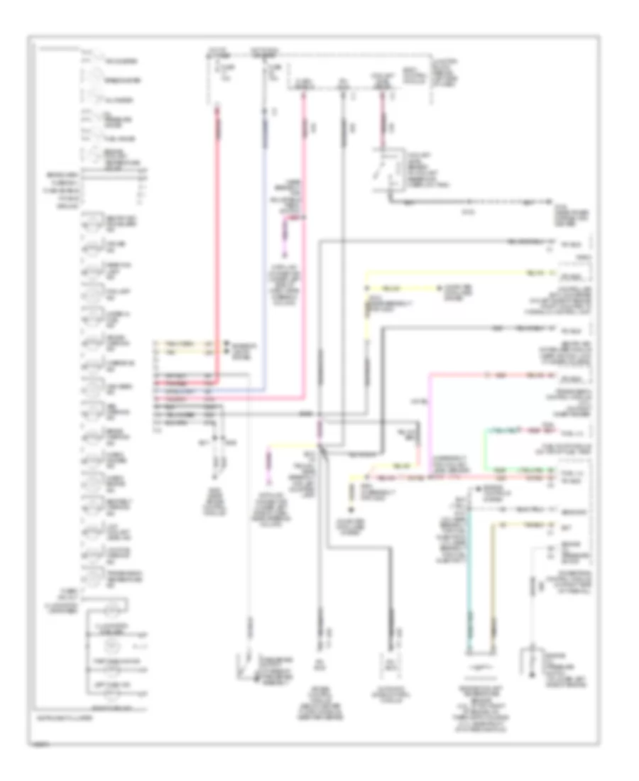
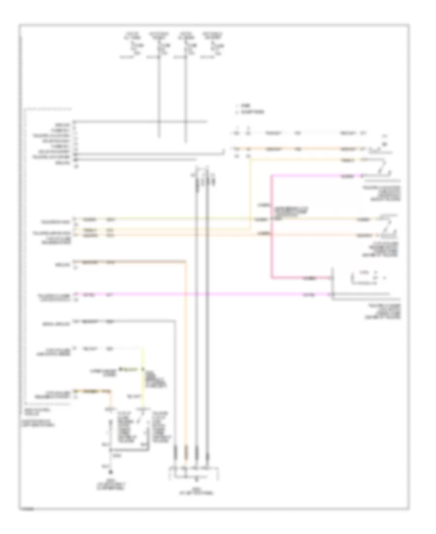
INSTRUMENT CLUSTER
Instrument Cluster Wiring Diagram for Jeep Grand Cherokee Limited 2004
List of elements for Instrument Cluster Wiring Diagram for Jeep Grand Cherokee Limited 2004:
- (4.7l)
- (in breakout for coolant level sensor)
- (near breakout for adjustable pedal switch) s223
- Abs warning ind
- Air bag control module (below center floor console, near park brake)
- Air bag warning ind
- Automatic zone control module
- Body control module
- Brake warn
- Brake warning ind
- Check engine ind
- Check gauges ind
- Computer data lines system
- Controller anti-lock brake (on left side of engine compt, mounted to hydraulic control unit)
- Coolant level sense
- Coolant level sensor (in coolant reservoir/ overflow tank)
- Cruise ind
- D19
- D25
- Data link connector (under left side of dash, near steering column)
- Ect
- Engine controls system
- Engine coolant temperature gauge
- Engine coolant temperature sensor (4.0l: at top front of engine, on thermostat housing) (4.7l: near front of intake manifold)
- Engine oil pressure sw sig
- Engine oil pressure switch (at lower left side of engine)
- Exterior lights system
- F33
- Flash enable
- Fog lamp ind
- For c200)
- Fuel gauge
- Fuel lvl
- Fuel pump module (on top of fuel tank)
- Fuse 10a
- Fused b(+)
- Fused ign out
- G108 (near power distribution center)
- G18
- G200 (near air bag control module)
- G60
- Ground
- High beam ind
- Hot at all times
- Hot in run or start
- Illumination (5 bulbs)
- Illumination lamps feed
- Instrument cluster
- Junction block (behind left side of dash)
- K226
- L60
- L61
- Left turn ind
- Low coolant level ind
- Low fuel warning ind
- Oil pressure gauge
- Overdrive ind
- Park brake switch (at base of park brake assembly)
- Part time 4wd ind
- Pci bus
- Pnk/red
- Powertrain control module (on right side of firewall)
- Radio
- Rear fog lamp ind
- Right turn ind
- S107 (4.0l:near breakout for fuel injector 6) (4.7l:near breakout for fuel injector 7)
- S130
- S132
- S203
- S210 (in trough, near breakout for left courtesy lamp)
- S211
- S226
- S324 (in breakout for c200)
- Seat belt warning ind
- Sens gnd
- Sentry key immobilizer ind
- Sentry key immobilizer module (near ignition lock cylinder housing)
- Speedometer
- Tachometer
- Tan
- Transmission control module (4.7l) (on right inner fender)
- Transmission temperature ind
- Voltmeter
- Water in fuel ind
- Z132
- Z300
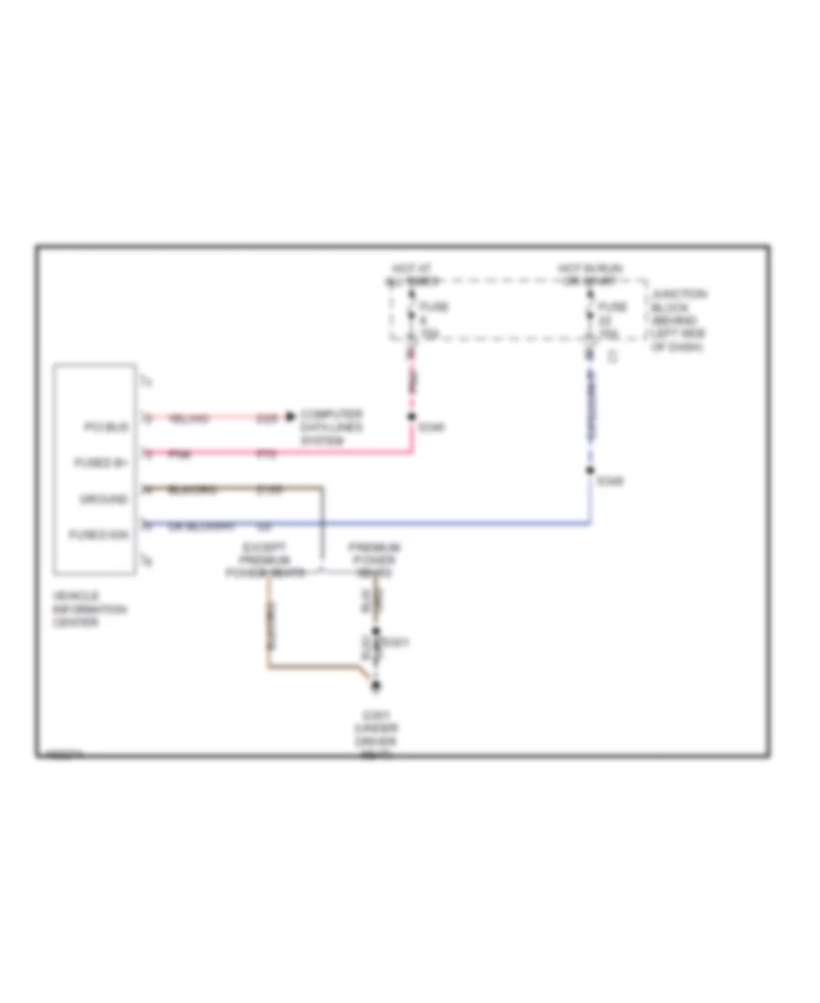
Vehicle Information System Wiring Diagram for Jeep Grand Cherokee Limited 2004
List of elements for Vehicle Information System Wiring Diagram for Jeep Grand Cherokee Limited 2004:
- Computer data lines system
- D25
- Except premium power seats
- F70
- Fuse 10a
- Fuse 15a
- Fused b+
- Fused ign
- G301 (under driver seat)
- Ground
- Hot at all times
- Hot in run or start
- Junction block (behind left side of dash)
- Pci bus
- Pnk
- Premium power seats
- S301
- S346
- S349
- Vehicle information center
- Z155
INTERIOR LIGHTS
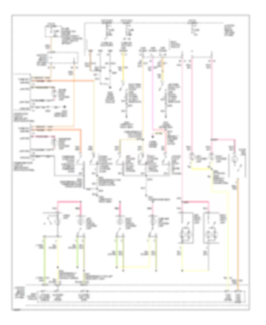
Courtesy Lamps Wiring Diagram for Jeep Grand Cherokee Limited 2004
List of elements for Courtesy Lamps Wiring Diagram for Jeep Grand Cherokee Limited 2004:
- (near breakout for liftgate lock motor) s378
- A146
- Ajar sns
- Ajar sw sns
- Body control module
- Breakout for radio connectors)
- Cargo lamp
- Courtesy lamp driver
- Courtesy lamp load shed
- Ctsy lamp driver
- Ctsy lamp load shed
- Driver door lock motor/ ajar switch (at rear of driver door)
- Driver door module (behind left front door panel)
- Driver front door courtesy lamp
- Fuse 10a
- Fuse 15a
- Fuse 50a
- Fused b(+)
- Fused ign (run-acc)
- Fused ign (run-start)
- G200 (near air bag control module)
- G300 (near right front seat)
- G301 (under driver seat)
- G74
- G75
- Glove box lamp
- Gnd
- Ground
- Hot at all times
- Hot in run or acc
- Hot in run or start
- Junction block (behind left side of dash)
- L121
- Lamp drv
- Lamp gnd
- Left courtesy lamp
- Left door handle courtesy lamp
- Left liftgate ajar switch (at left side of liftgate)
- Left rear door lock motor/ ajar switch (at rear of left rear door)
- Left visor/ vanity lamp
- Liftgate courtesy disable
- Liftgate flip-up ajar switch (at center of liftgate)
- M21
- Overhead map/ courtesy lamp
- Passenger door lock motor/ ajar switch (at rear of passenger door)
- Passenger door module (behind right front door panel)
- Passenger front door courtesy lamp
- Pnk
- Pnk pnk
- Power distribution center (at right front corner of engine compt, next to battery)
- Right courtesy lamp
- Right door handle courtesy lamp
- Right liftgate ajar switch (at right side of liftgate)
- Right rear door lock motor/ ajar switch (at rear of right rear door)
- Right visor/ vanity lamp
- S205
- S207
- S211
- S330
- S336
- S338 (near breakout for passenger power window motor)
- S346
- S347 (near breakout for left visor/vanity lamp)
- S356
- S357
- S376
- S379 (in breakout for rear wiper motor)
- Tan/ g76
- Tan/ g77
- Tan/ g78
- Tan/ red
- Tan/red
- Window motor)
- Wiper/ washer system
- Z28
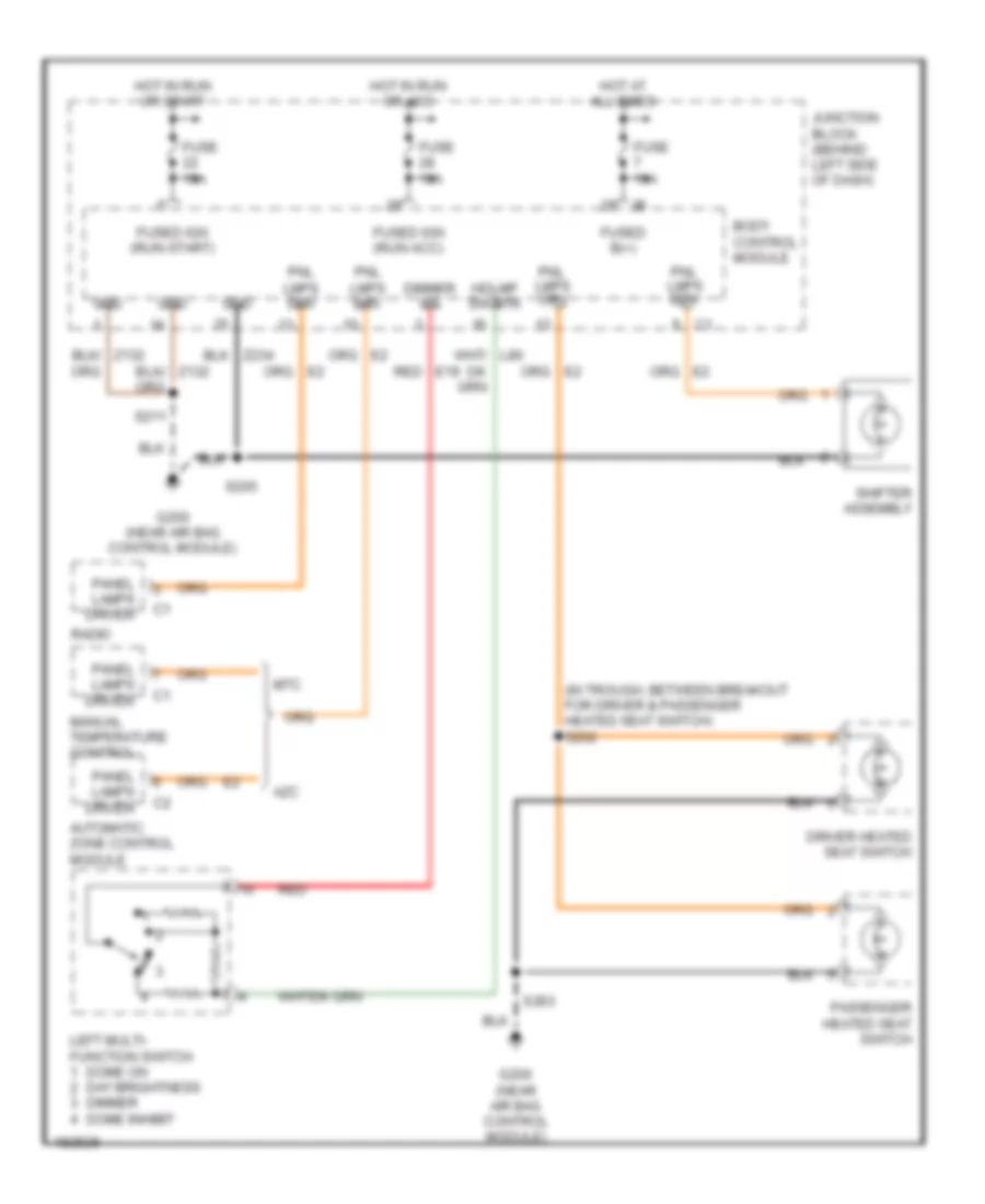
Instrument Illumination Wiring Diagram for Jeep Grand Cherokee Limited 2004
List of elements for Instrument Illumination Wiring Diagram for Jeep Grand Cherokee Limited 2004:
- (in trough, between breakout for driver & passenger heated seat switch) s202
- Automatic zone control module
- Azc
- Body control module
- Dimmer sig
- Dome on day brightness dimmer dome inhibit
- Driver heated seat switch
- Fuse 10a
- Fused b(+)
- Fused ign (run-acc)
- Fused ign (run-start)
- G200 (near air bag control module)
- Gnd
- Hdlmp sw rtn
- Hot at all times
- Hot in run or acc
- Hot in run or start
- Junction block (behind left side of dash)
- Left multi- function switch
- Manual temperature control
- Mtc
- Panel lamps driver
- Passenger heated seat switch
- Pnl lmps drv
- Radio
- Red
- Red e19
- S203
- S205
- S211
- Shifter assembly
MEMORY SYSTEMS
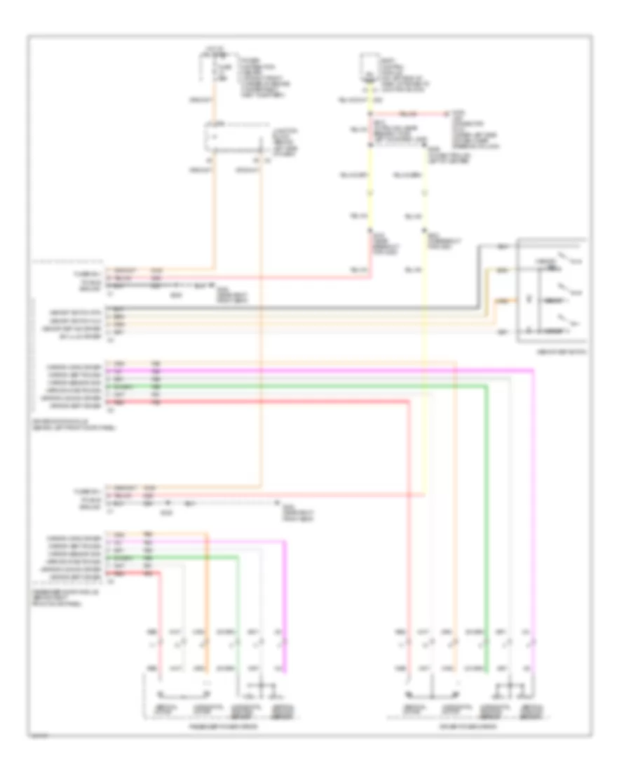
Memory Mirrors Wiring Diagram for Jeep Grand Cherokee Limited 2004
List of elements for Memory Mirrors Wiring Diagram for Jeep Grand Cherokee Limited 2004:
- A146
- Body control module (on left end of dash, attached to junction block)
- D25
- Data
- Driver door module (behind left front door panel)
- Driver power mirror
- Fuse 50a
- Fused b(+)
- G300 (near right front seat)
- Ground
- Horizontal motor
- Horizontal position sensor
- Hot at all times
- Junction block (behind left side of dash)
- Link connector (dlc) (under left side of dash, near steering column)
- Memory 1
- Memory 2
- Memory set
- Memory set ind driver
- Memory set switch
- Memory switch mux
- Memory switch rtn
- Mirror common driver
- Mirror horiz driver
- Mirror horiz pos sig
- Mirror sensor gnd
- Mirror vert driver
- Mirror vert pos sig
- P64
- P65
- P69
- P91
- P93
- P95
- Passenger door module (behind right front door panel)
- Passenger power mirror
- Pci bus
- Power distribution center (at right front corner of engine compartment, next to battery)
- Red
- S210 (in trough, near breakout for left courtesy lamp)
- S226 (in dash trough, left of center)
- S312 (near breakout for c200)
- S324 (in breakout for c200)
- S336
- S338
- Sw illum driver
- Vertical motor
- Vertical position sensor
- Z28
Memory Seat Wiring Diagram for Jeep Grand Cherokee Limited 2004
List of elements for Memory Seat Wiring Diagram for Jeep Grand Cherokee Limited 2004:
- (near breakout for seat belt switch)
- Circuit breaker 2 20a
- Computer data lines system
- D25
- Driver door module (behind left front door panel)
- Driver heated seat module (under driver seat)
- Driver power seat front riser motor (at driver seat)
- Driver power seat front riser motor sensor (at driver seat)
- Driver power seat horizontal motor (at driver seat)
- Driver power seat horizontal motor sensor (at driver seat)
- Driver power seat rear riser motor (at driver seat)
- Driver power seat rear riser motor sensor (at driver seat)
- Driver power seat recliner motor (at driver seat)
- Driver power seat recliner motor sensor (at driver seat)
- Driver power seat switch
- Drv seat htr (b+)
- Drv seat temp sens
- F35
- Front riser pos sig
- Fused (b+)
- Fwd
- G301 (under driver seat)
- Gnd
- Ground
- Hot at all times
- Junction block (behind left side of dash)
- Memory 1
- Memory 2
- Memory set
- Memory set ind drv
- Memory set switch
- Memory switch mux
- Memory switch rtn
- P11
- P111
- P113
- P115
- P117
- P119
- P121
- P13
- P130
- P131
- P135
- P141
- P143
- P15
- P17
- P19
- P21
- P25
- P26
- P27
- P28
- P29
- P41
- P43
- P47
- P86
- Pass seat htr (b+)
- Pass seat temp sens
- Pci bus
- Rear riser pos sig
- Recline
- Recliner dwn sw sns
- Recliner pos sig
- Recliner up sw sns
- Red
- Rwd
- S301
- S312 (near breakout for c200)
- S335
- S351
- S352
- S353
- S355
- Seat frnt
- Seat front dwn drv
- Seat front dwn sw sns
- Seat front up drv
- Seat front up sw sns
- Seat horiz
- Seat horiz fwd drv
- Seat horiz fwd sw sns
- Seat horiz pos sig
- Seat horiz rear drv
- Seat horiz rear sw sns
- Seat pos sensor gnd
- Seat rear
- Seat rear dwn drv
- Seat rear dwn sw sns
- Seat rear up drv
- Seat rear up sw sns
- Seat recliner dwn drv
- Seat recliner up drv
- Seat sensor 5v
- Seat switch (b+)
- Seats system
- Switch illum drv
- Z155
- Z243
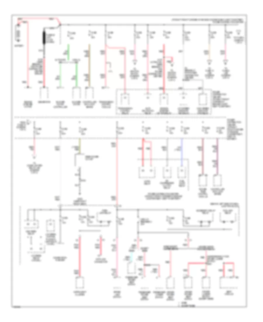
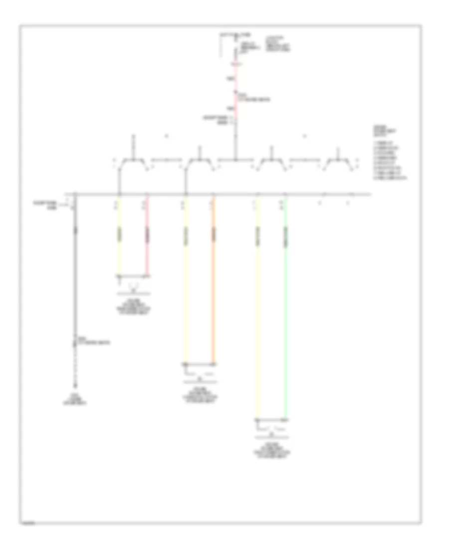
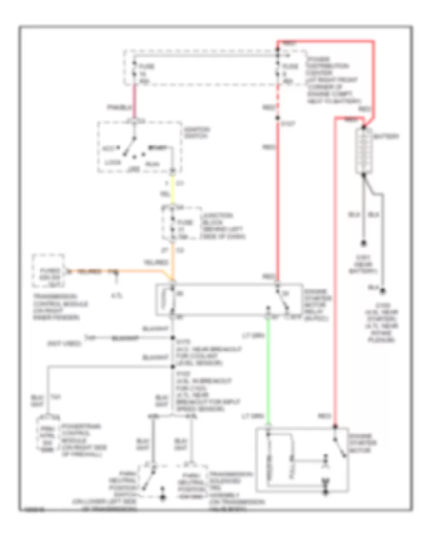
POWER DISTRIBUTION
Power Distribution Wiring Diagram (1 of 3) for Jeep Grand Cherokee Limited 2004
List of elements for Power Distribution Wiring Diagram (1 of 3) for Jeep Grand Cherokee Limited 2004:
- (at right front corner of engine compartment, next to battery) power distribution center
- (behind left side of dash) junction block
- (in breakout for power distribution center) s180
- (near breakout for red
- 4.7l
- A/c compressor clutch relay
- Accessory delay relay
- Auto shutdown relay
- Automatic a/c
- Base
- Base except heated seats
- Battery
- Blower motor
- Blower motor controller
- Brake lamp switch
- Circuit breaker 2 20a
- Combination flasher
- Controller anti-lock brake
- Data link connector
- Driver lumbar switch (except base)
- Driver lumbar switch) s353
- Driver power seat switch
- Engine starter motor
- Engine starter motor relay
- Except base
- Fog lamp relay
- From a fuse 15 (diagram 1 of 3)
- Fuel pump relay
- Fuse 10a
- Fuse 15a
- Fuse 20a
- Fuse 30a
- Fuse 40a
- Fuse 40a (4.0l)
- Fuse 50a
- G300 (near right front seat)
- Generator
- Heated seats/ midline/premium
- High beam relay
- High speed radiator fan relay
- Horn relay
- Instrument cluster
- Low beam relay (w/o drl)
- Low beam/ daytime running lamp relay (w/ drl)
- Low speed radiator fan relay
- Manual a/c
- Nca
- Park lamp relay
- Passenger lumbar switch
- Passenger power seat switch
- Pnk/ red
- Power distribution center (at right front corner of engine compartment, next to battery)
- Power distribution center (at right front corner of engine compt, next to battery)
- Power- train control module
- Rear power outlet
- Red
- Red/ tan
- S127 (in trough, near breakout for power distribution center)
- S332
- S342
- Seat module
- To cigar lighter relay (j/b) (diagram 2 of 3)
- To fuse 18 (j/b) (diagram 3 of 3)
- To fuse 2 (diagram 1 of 3)
- To fuse 8 (j/b) (diagram 2 of 3)
- To ignition switch (diagram 2 of 3)
- Transmission control module
- Transmission control relay
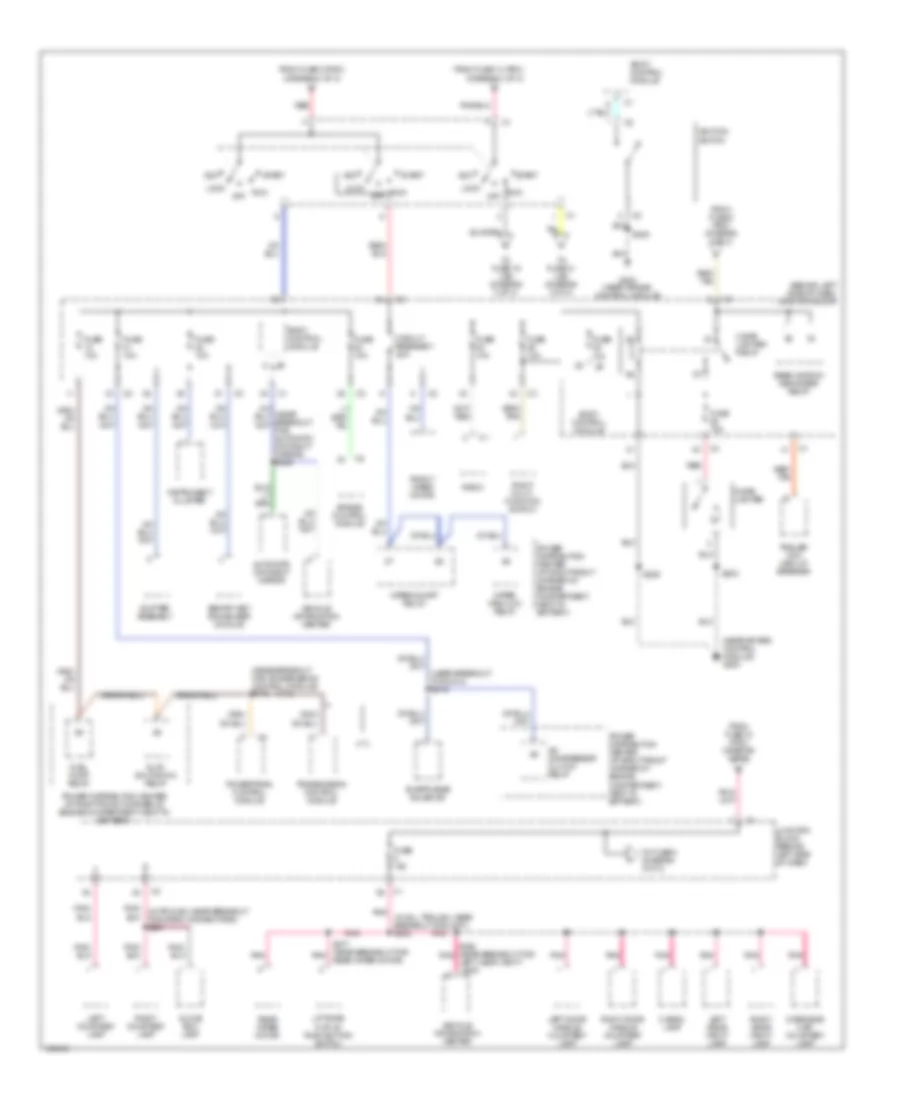
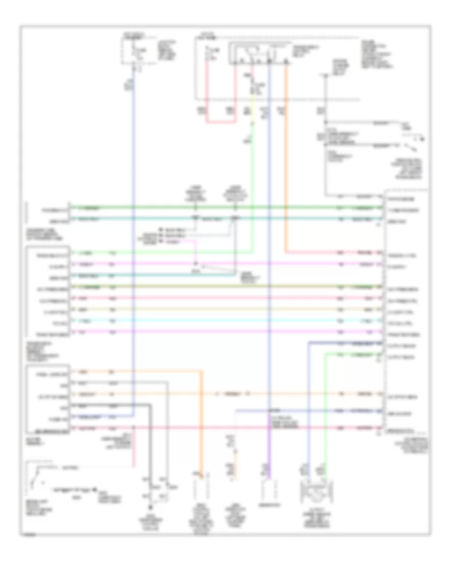
Power Distribution Wiring Diagram (2 of 3) for Jeep Grand Cherokee Limited 2004
List of elements for Power Distribution Wiring Diagram (2 of 3) for Jeep Grand Cherokee Limited 2004:
- (4.7l)
- (behind left side of dash) junction block
- (diagram 1 of 3)
- (in sill trough, near breakout for c307) s304
- (near air bag control module) g200
- (near breakout for c314) s316
- (near breakout for transmission control module) s116
- 4.7l
- A/c compressor clutch relay
- Acc
- Air bag control module
- Auto shutdown relay
- Automatic day/night mirror
- Body control module
- Cargo lamp
- Cigar lighter
- Cigar lighter relay
- Circuit breaker 1 20a
- Evap/purge solenoid
- From fuse 14 (pdc)
- From fuse 15 (pdc) (diagram 1 of 3)
- From fuse 2 (pdc) (diagram 1 of 3)
- From fuse 8 (pdc) (diagram 1 of 3)
- Front wiper motor
- Fuel pump relay
- Fuse 10a
- Fuse 15a
- G200 (near air bag control module)
- Glove box lamp
- Ignition switch
- Instrument cluster
- Junction block (behind left side of dash)
- Left courtesy lamp
- Left door handle courtesy lamp
- Left visor/ vanity lamp
- Liftgate flip-up push button switch
- Lock
- Overhead map/ courtesy lamp
- Pnk
- Pnk/ (in trough, near breakout for radio connectors) s207
- Power distribution center (at right front corner of engine compartment, next to battery)
- Powertrain control module
- Radio
- Rear window defogger relay
- Rear wiper motor
- Rear wiper motor)
- Red
- Red/ tan
- Right courtesy lamp
- Right door handle courtesy lamp
- Right multi- function switch
- Right visor/ vanity lamp
- Run off
- S203
- S205
- S346 (near breakout for pnk left visor vanity lamp)
- S377 (near breakout for pnk
- Sentry key immobilizer module
- Shifter assembly
- Start
- To fuse 19 (j/b) (diagram 3 of 3)
- To fuse 31 (j/b) (diagram 3 of 3)
- To fuse 5 (diagram 3 of 3)
- Trailer tow circuit breaker
- Transmission control module
- Vehicle information center
- Wiper high/low relay
- Wiper on/off relay
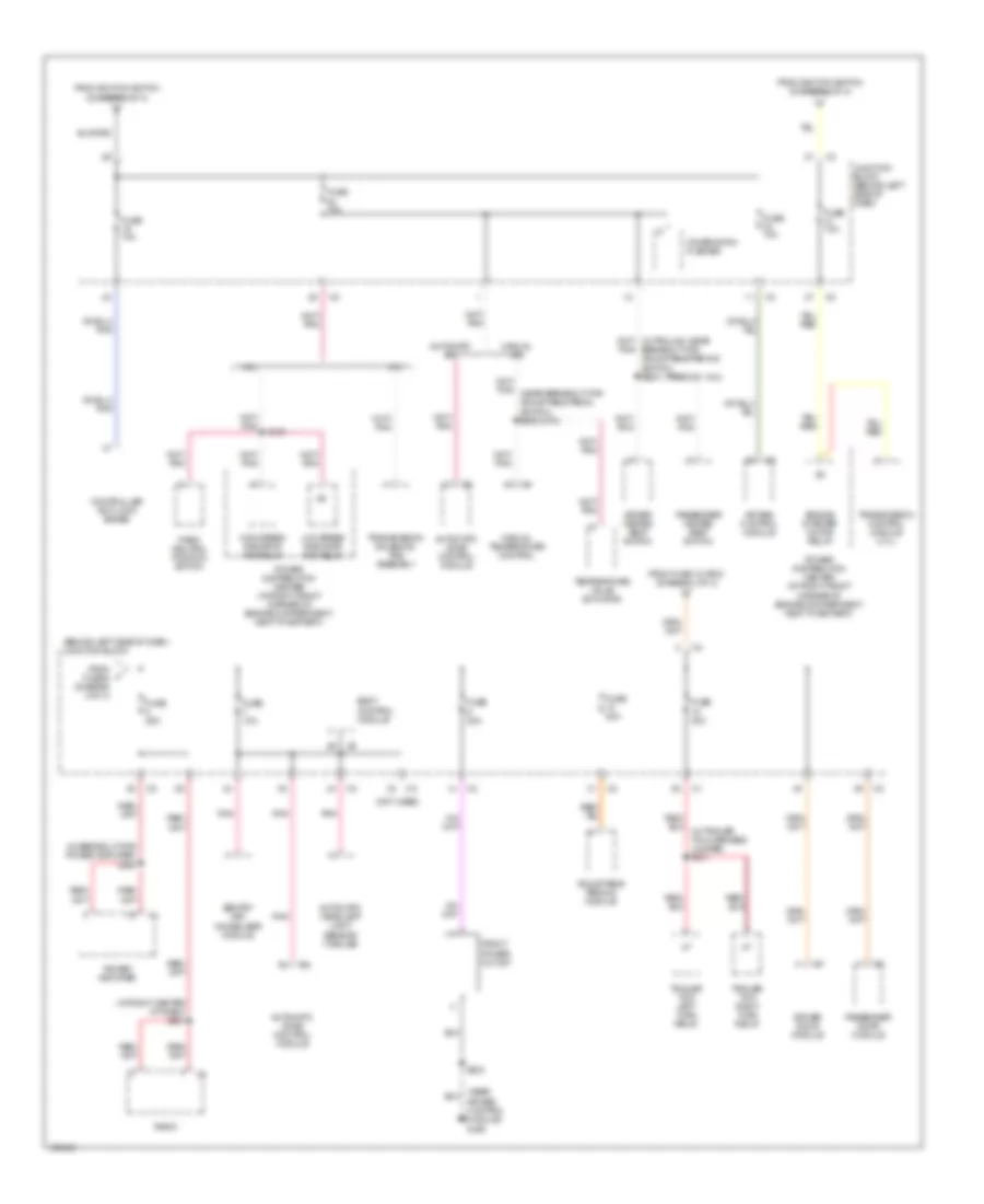
Power Distribution Wiring Diagram (3 of 3) for Jeep Grand Cherokee Limited 2004
List of elements for Power Distribution Wiring Diagram (3 of 3) for Jeep Grand Cherokee Limited 2004:
- (at right center of dash) s221
- (behind left side of dash) junction block
- (in breakout for power amplifier) s334
- (near air bag control module) g200
- (not used)
- (premium 1 & 3)
- 4.0l
- 4.7l
- Adjustable pedals module
- Air bag control module
- Automatic a/c
- Automatic headlamp light sensor/ vtss led
- Automatic zone control module
- Body control module
- Breakout for adjustable pedals switch) s204
- Combination flasher
- Controller anti-lock brake
- Driver door module
- Driver heated seat switch
- Engine starter motor relay
- From fuse 12 (pdc) (diagram 1 of 3)
- From ignition switch (diagram 2 of 3)
- From j fuse 8 (diagram 2 of 3)
- Front power outlet
- Fuse 10a
- Fuse 20a
- Fuse 25a
- Fuse 30a
- High speed radiator fan relay
- Junction block (behind left side of dash)
- Low speed radiator fan relay
- Manual a/c
- Manual temperature control
- Park/ neutral position switch
- Passenger door module
- Passenger heated seat switch
- Pnk
- Power amplifier
- Power distribution center (at right front corner of engine compartment, next to battery)
- Radio
- S181
- S203
- Sentry key immobilizer module
- Temperature valve actuator
- Trailer tow left turn relay
- Trailer tow right turn relay
- Transmission control module (4.7l)
- Transmission solenoid/ trs assembly
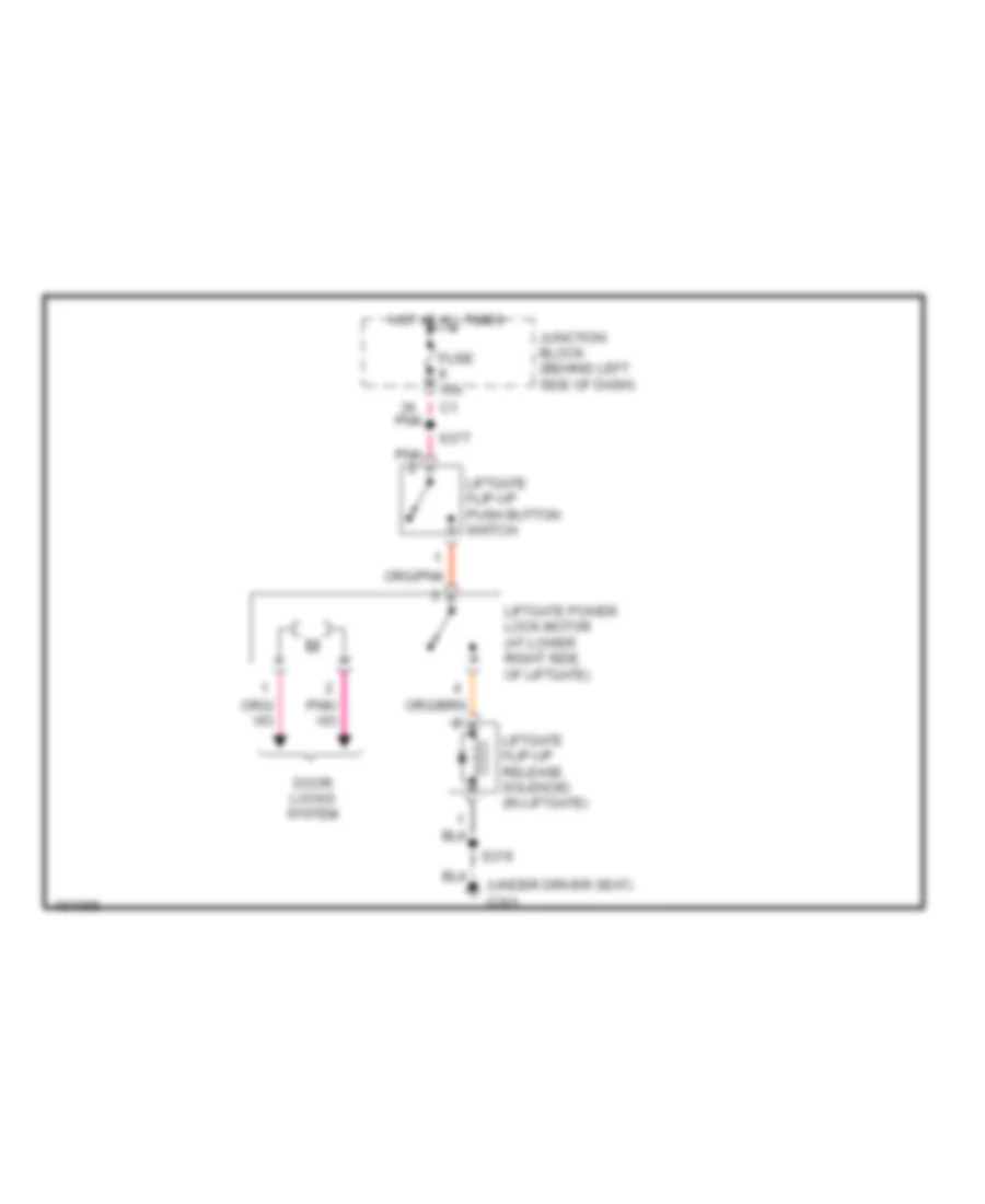
POWER DOOR LOCKS
Power Door Locks Wiring Diagram for Jeep Grand Cherokee Limited 2004
List of elements for Power Door Locks Wiring Diagram for Jeep Grand Cherokee Limited 2004:
- (between troughs, near breakout for c314)
- (in breakout for passenger door module)
- (in sill trough, near breakout for c307)
- (in trough near breakout for left courtesy lamp) s210
- (near breakout for c200)
- (near breakout for passenger power window motor)
- (near ignition lock cylinder housing)
- A146
- Body control module
- Computer data lines system
- D25
- Door lock
- Door unlock driver
- Dr unlock
- Driver cylinder lock switch (at rear of driver door)
- Driver door lock
- Driver door lock motor/ ajar switch (at rear of driver door)
- Driver door module (behind left front door panel)
- Flip-up ajar
- Fuse 15a
- Fuse 50a
- Fused b+
- G300 (near right front seat)
- G301 (under driver seat)
- G73
- G74
- G75
- G76
- G77
- G78
- G80
- Ground
- Hot at all times
- Junction block (behind left side of dash)
- Left liftgate ajar switch (at left side of liftgate)
- Left rear door lock motor/ ajar switch (at rear of left rear door)
- Lf door ajar sw
- Lf key cyl sw sense
- Liftgate ajar
- Liftgate flip-up ajar switch (at center of liftgate)
- Liftgate flip-up push button switch
- Liftgate flip-up release solenoid (in liftgate)
- Liftgate power lock motor (at lower right side of liftgate)
- Limit switch
- Lr door ajar
- P34
- P35
- P36
- Passenger door module (behind right front door panel)
- Passenger front door lock motor/ ajar switch (at rear of passenger door)
- Pci bus
- Pnk
- Power distribution center (at right front corner of engine compartment, next to battery)
- Rear wiper motor (on liftgate inner panel)
- Rf ajar sw
- Right liftgate ajar switch (at right side of liftgate)
- Right rear door lock motor/ ajar switch (at rear of right rear door)
- Rr door ajar
- S226 (in dash trough, left of center)
- S302
- S303
- S312
- S317
- S318
- S324 (in breakout for c200)
- S336
- S338
- S338 s338
- S339
- S340
- S356
- S357
- S376
- S377
- S378 (near breakout for liftgate lock motor)
- S379 (in breakout for rear wiper motor)
- Sentry key immobilizer module
- Tan/ red
- Tan/red
- Z28
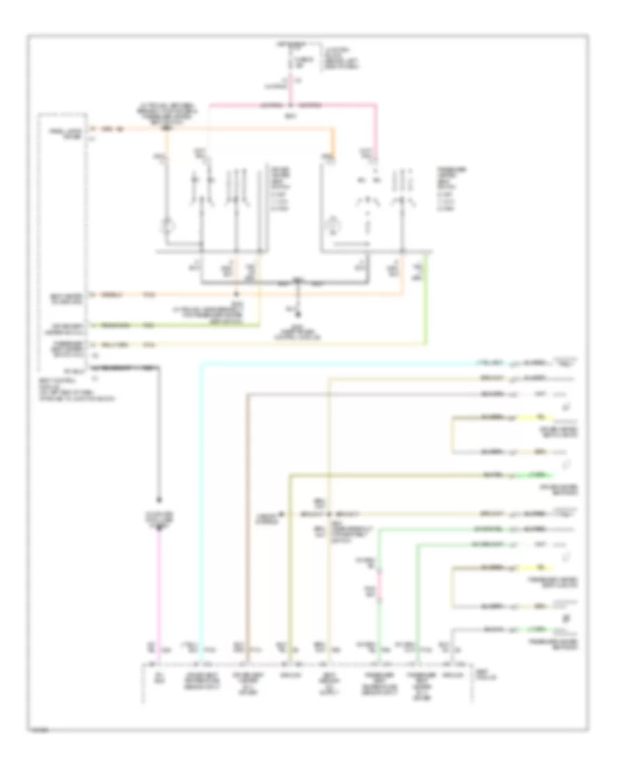
POWER MIRRORS
Power Mirrors Wiring Diagram for Jeep Grand Cherokee Limited 2004
List of elements for Power Mirrors Wiring Diagram for Jeep Grand Cherokee Limited 2004:
- (in dash trough, left of center) s226
- (on lower left side of transmission) park/ neutral position switch
- (on transmission valve body) transmission solenoid/trs assembly
- (under left side of dash, near steering column) data link connector (dlc)
- 4.0l
- 4.7l
- A146
- Auto day/ night mirror b(+)
- Auto day/ night mirror b(-)
- Automatic day/night mirror
- Backup lamp feed
- Body control module (on left end of dash, attached to junction block)
- D25
- Defogger system
- Driver door module (behind left front door panel)
- Driver power mirror
- Exterior lights system
- For 106)
- Front seat)
- Fuse 22 10a
- Fuse 50a
- Fused b(+)
- Fused ignition (run-start)
- G300 (near right
- G300 (near right front seat)
- G301 (under driver seat)
- Gnd
- Ground
- Horiz motor
- Horiz position sensor
- Hot at all times
- Hot in run or start
- Junction block (behind left side of dash)
- Mirror common drv
- Mirror heater
- Mirror horiz drv
- Mirror horiz pos sig
- Mirror sensor gnd
- Mirror vert drv
- Mirror vert pos sig
- P64
- P65
- P69
- P91
- P93
- P95
- Passenger door module (behind right front door panel)
- Passenger power mirror
- Pci bus
- Power distribution center (at right front corner of engine compartment, next to battery)
- Red
- S310 (between breakout for c310 & left rear lamp assembly)
- S312 (near breakout for c200)
- S324 (in breakout for c200)
- S336
- S338
- S345 (w/ sunroof)
- S349
- Vert motor
- Vert position sensor
- Z28
POWER SEATS
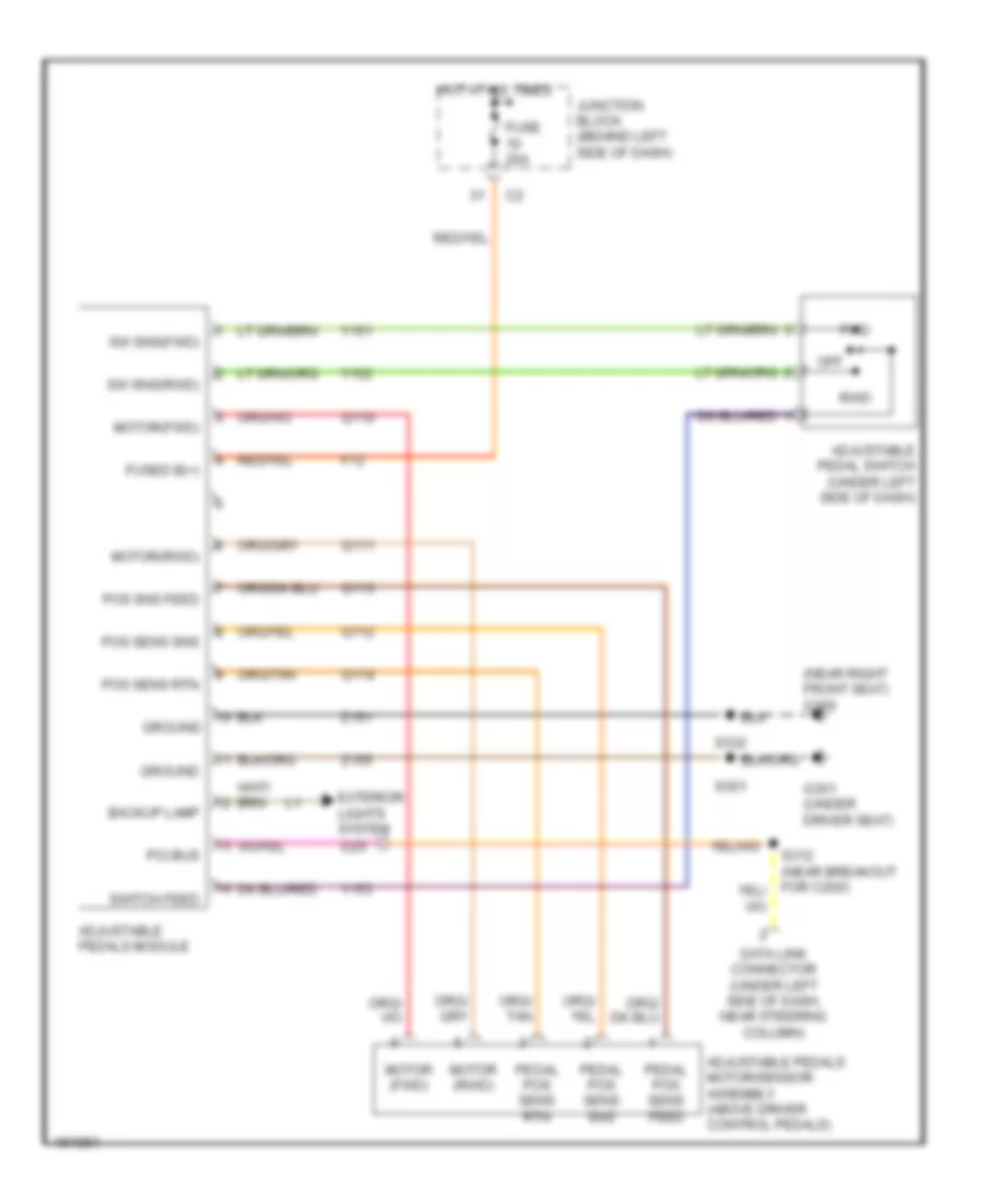
Adjustable Pedal Wiring Diagram for Jeep Grand Cherokee Limited 2004
List of elements for Adjustable Pedal Wiring Diagram for Jeep Grand Cherokee Limited 2004:
- (near right front seat) g300
- Adjustable pedal switch (under left side of dash)
- Adjustable pedals module
- Adjustable pedals motor/sensor assembly (above driver control pedals)
- Backup lamp
- Data link connector (under left side of dash, near steering column)
- Exterior lights system d25
- F72
- Fuse 20a
- Fused b(+)
- Fwd
- G301 (under driver seat)
- Ground
- Hot at all times
- Junction block (behind left side of dash)
- Motor (fwd)
- Motor (rwd)
- Motor(fwd)
- Motor(rwd)
- Off
- Pci bus
- Pedal pos sens feed
- Pedal pos sens rtn
- Pedal pos sens sns
- Pos sens rtn
- Pos sens sns
- Pos sns feed
- Q110
- Q111
- Q112
- Q113
- Q114
- Rwd
- S301
- S332
- Sw sns(fwd)
- Sw sns(rwd)
- Switch feed
- Y151
- Y152
- Y153
- Z151
- Z155
Driver Power Seat Wiring Diagram for Jeep Grand Cherokee Limited 2004
List of elements for Driver Power Seat Wiring Diagram for Jeep Grand Cherokee Limited 2004:
- (except base)
- 1) rear up
- 2) rear down
- 3) forward
- 4) rearward
- 5) front up
- 6) front down
- 7) recliner up
- 8) recliner down
- A (base)
- Base
- Circuit breaker 2 20a
- Driver power seat front riser motor (at driver seat)
- Driver power seat horizontal motor (at driver seat)
- Driver power seat rear riser motor (at driver seat)
- Driver power seat switch
- Except base
- G301 (under driver seat)
- Hot at all times
- Junction block (behind left side of dash)
- Red
- S353 (w/ heated seats)
- S355 (w/ heated seats)
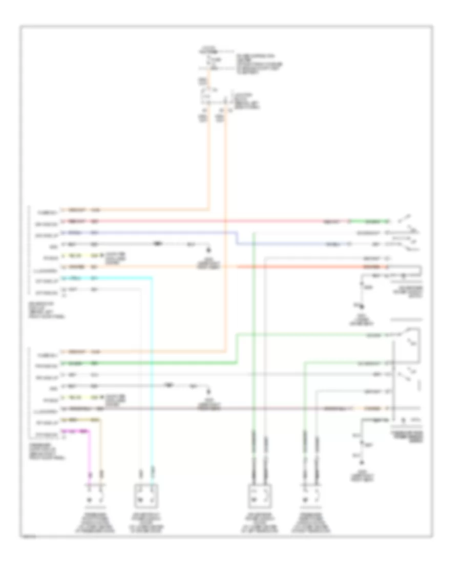
Heated Seats Wiring Diagram for Jeep Grand Cherokee Limited 2004
List of elements for Heated Seats Wiring Diagram for Jeep Grand Cherokee Limited 2004:
- (in trough, between breakout for driver & passenger heated seat switch) s202
- (on left end of dash, attached to junction block)
- 0) off
- 1) low
- 2) high
- Body control module
- Computer data lines system
- D25
- Driver heated seat back
- Driver heated seat cushion
- Driver heated seat switch
- Driver seat heater b (+) driver
- Driver seat heater sw mux
- Driver seat temperature sensor input
- For seat belt switch)
- Fuse 20 10a
- G200 (near air bag control module)
- Ground
- Hot in run
- Junction block (behind left side of dash)
- Memory systems
- P131
- P132
- P134
- P135
- P29
- Panel lamps driver
- Passenger heated seat back
- Passenger heated seat cushion
- Passenger heated seat switch
- Passenger seat heater b (+) driver
- Passenger seat heater switch mux
- Passenger seat temperature sensor input
- Pci bus
- Pi33
- S200 (in trough, near breakout for passenger heated seat switch)
- S203
- S204
- Seat heater sw sns gnd
- Seat module
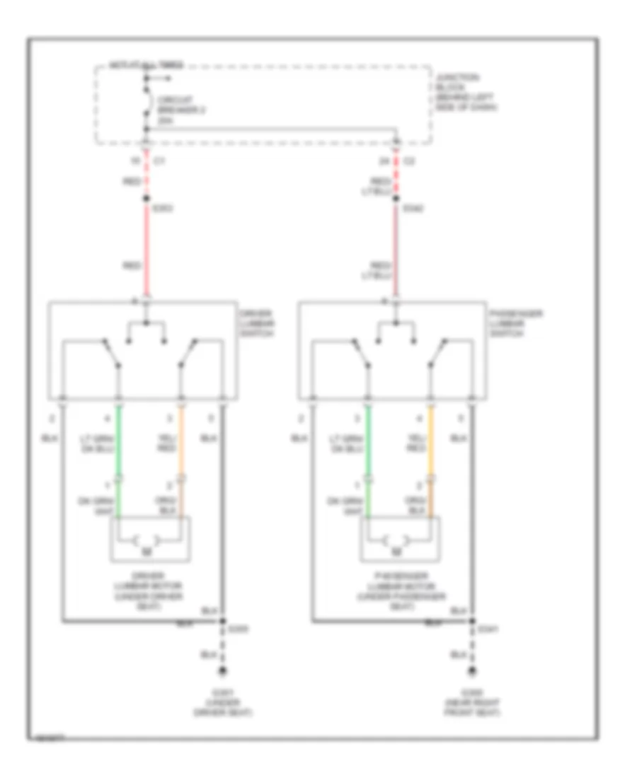
Lumbar Wiring Diagram for Jeep Grand Cherokee Limited 2004
List of elements for Lumbar Wiring Diagram for Jeep Grand Cherokee Limited 2004:
- Circuit breaker 2 20a
- Driver lumbar motor (under driver seat)
- Driver lumbar switch
- G300 (near right front seat)
- G301 (under driver seat)
- Hot at all times
- Junction block (behind left side of dash)
- Passenger lumbar motor (under passenger seat)
- Passenger lumbar switch
- Red
- S341
- S342
- S353
- S355
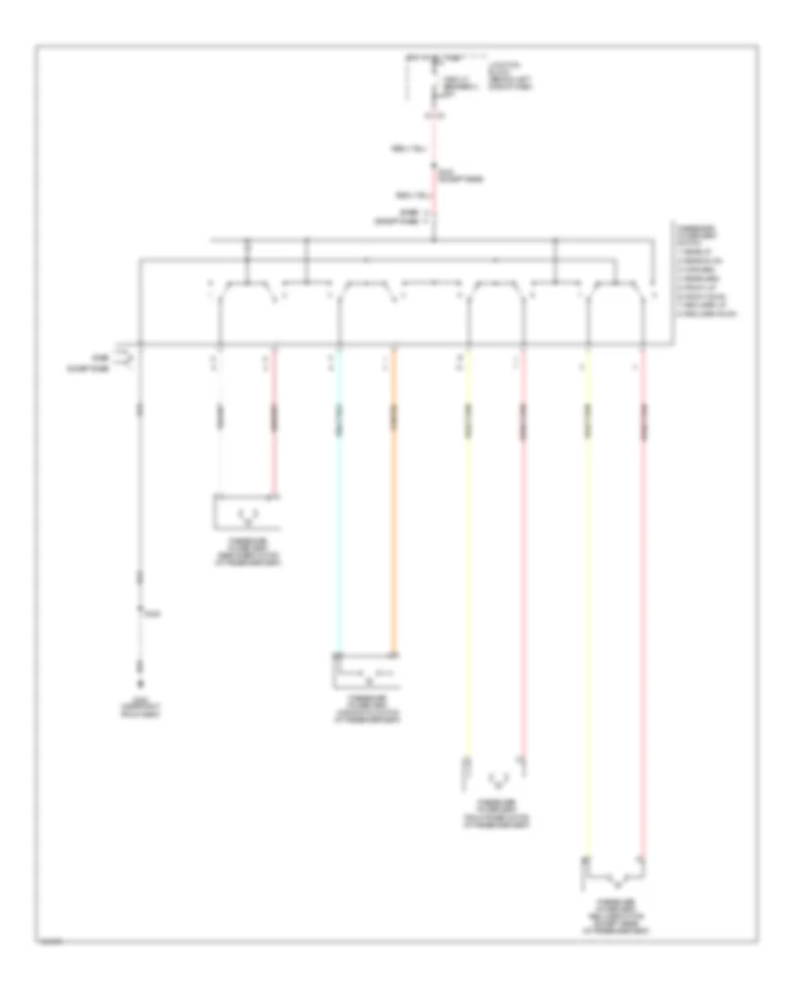
Passenger Power Seat Wiring Diagram for Jeep Grand Cherokee Limited 2004
List of elements for Passenger Power Seat Wiring Diagram for Jeep Grand Cherokee Limited 2004:
- (except base)
- 1) rear up
- 2) rear down
- 3) forward
- 4) rearward
- 5) front up
- 6) front down
- 7) recliner up
- 8) recliner down
- A (base)
- Base
- Circuit breaker 2 20a
- Except base
- G300 (near right front seat)
- Hot at all times
- Junction block (behind left side of dash)
- Passenger power seat front riser motor (at passenger seat)
- Passenger power seat horizontal motor (at passenger seat)
- Passenger power seat rear riser motor (at passenger seat)
- Passenger power seat recliner motor (except base) (at passenger seat)
- Passenger power seat switch
- S329
- S342 (except base)
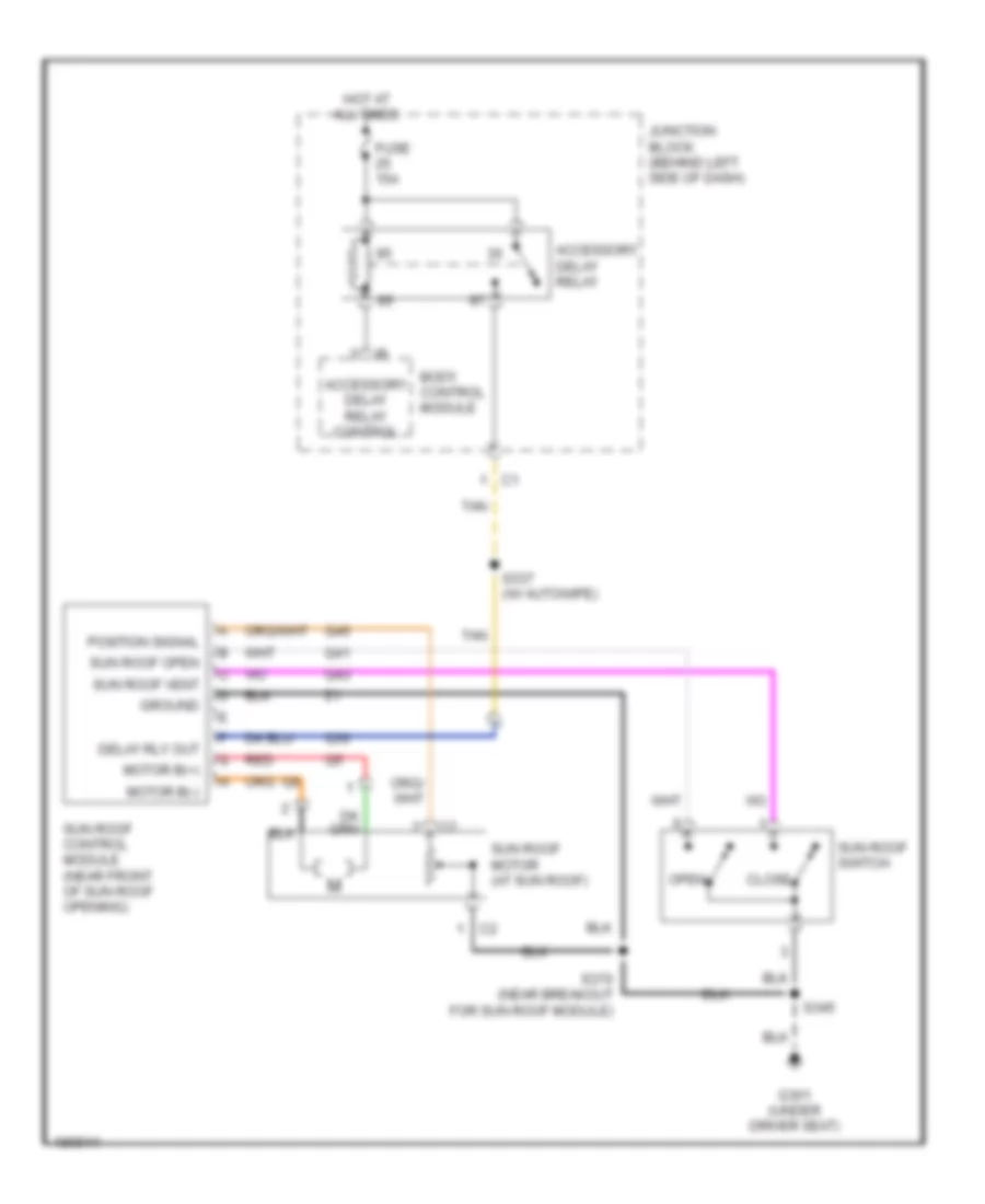
POWER TOP/SUNROOF
Power Top/Sunroof Wiring Diagram for Jeep Grand Cherokee Limited 2004
List of elements for Power Top/Sunroof Wiring Diagram for Jeep Grand Cherokee Limited 2004:
- Accessory delay relay
- Accessory delay relay control
- Body control module
- Close
- Delay rly out
- Fuse 15a
- G301 (under driver seat)
- Ground
- Hot at all times
- Junction block (behind left side of dash)
- Motor b(+)
- Motor b(-)
- Open
- Position signal
- Q30
- Q41
- Q43
- Q46
- Red
- S337 (w/ autowipe)
- S345
- S370 (near breakout for sun roof module)
- Sun roof control module (near front of sun roof opening)
- Sun roof motor (at sun roof)
- Sun roof open
- Sun roof switch
- Sun roof vent
- Tan
POWER WINDOWS
Power Windows Wiring Diagram for Jeep Grand Cherokee Limited 2004
List of elements for Power Windows Wiring Diagram for Jeep Grand Cherokee Limited 2004:
- A146
- Computer data lines system
- D/f wind dn
- D/f wind up
- D/r wind dn
- D/r wind up
- D25
- Driver door module (behind left front door panel)
- Driver front power window motor (at lower center of driver door)
- Driver rear power window motor (at lower center of left rear door)
- Driver rear power window switch
- E20
- E21
- Fuse 50a
- Fused b(+)
- G300 (near right front seat)
- G301 (under driver seat)
- Gnd
- Hot at all times
- Illumination
- Junction block (behind left side of dash) c2
- Nca
- P/f wind dn
- P/f wind up
- P/r wind dn
- P/r wind up
- Passenger door module (behind right front door panel)
- Passenger front power window motor (at lower center of passenger door)
- Passenger rear power window motor (at lower center of right rear door)
- Passenger rear power window power window switch switch
- Pci bus
- Power distribution center (at right front corner of engine compt, next to battery)
- Q11
- Q12
- Q13
- Q14
- Q21
- Q22
- Q23
- Q24
- S336
- S338
- S356
- S357
- Z28
RADIO
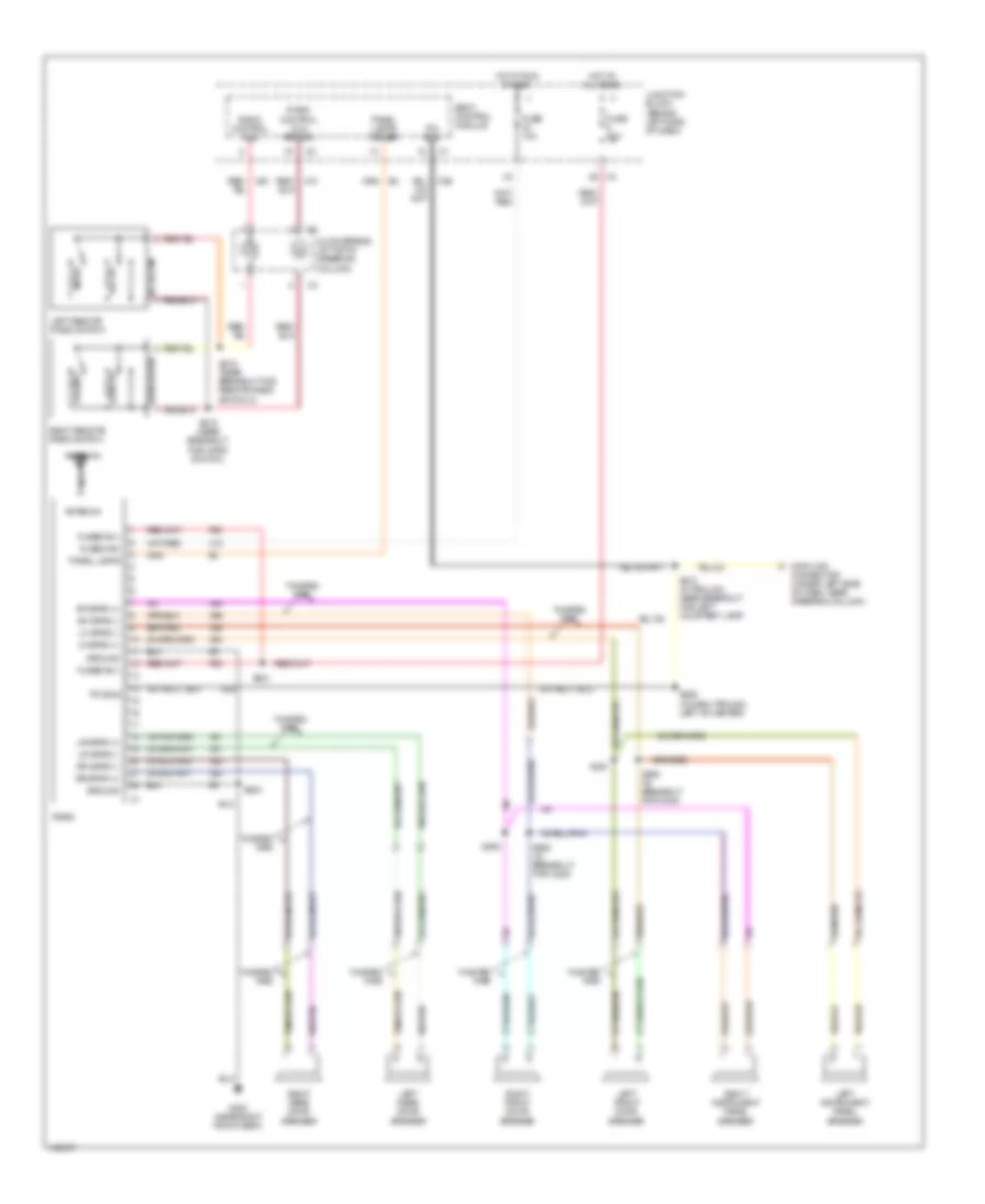
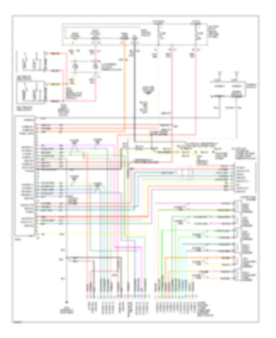
Radio Wiring Diagram, Base Radio for Jeep Grand Cherokee Limited 2004
List of elements for Radio Wiring Diagram, Base Radio for Jeep Grand Cherokee Limited 2004:
- Antenna
- Body control module
- Clockspring (at top of steering column)
- Connector (under left side of dash, near steering column)
- D25
- Data link
- F60
- Fuse 10a
- Fuse 25a
- Fused b(+)
- Fused ign
- G300 (near right front seat)
- Ground
- Hot at all times
- Hot in run or acc
- Junction block (behind left side of dash)
- Left front door speaker
- Left instrument panel speaker
- Left rear door speaker
- Left remote radio switch
- Lf spkr (+)
- Lf spkr (-)
- Lr spkr (+)
- Lr spkr (-)
- Mode
- Nca
- Panel lamps
- Panel lamps driver
- Pci bus
- Preset
- Radio
- Radio control mux
- Radio control mux return
- Rf spkr (+)
- Rf spkr (-)
- Right front door speaker
- Right instrument panel speaker
- Right rear door speaker
- Right remote radio switch
- Rr spkr (+)
- Rr spkr (-)
- S210 (in trough, near breakout for left courtesy lamp)
- S215 (near breakout for horn switch)
- S216 (near breakout for remote radio switch 2)
- S221
- S224
- S226 (in dash trough, left of center)
- S360 (in breakout for c302)
- S361
- S362 (in breakout for c200)
- S363
- Seek down
- Seek up
- Twisted pair
- Vol down
- Vol up
- X10
- X12
- X20
- X51
- X52
- X53
- X54
- X55
- X56
- X57
- X58
Radio Wiring Diagram, Premium Radio for Jeep Grand Cherokee Limited 2004
List of elements for Radio Wiring Diagram, Premium Radio for Jeep Grand Cherokee Limited 2004:
- (in dash trough, left of center)
- (in trough, near breakout for left courtesy lamp) s210
- (near breakout for power amplifier)
- Antenna
- Antenna module
- Audio out l
- Audio out r
- B(+)
- Body control module
- Clockspring (at top of steering column)
- Compact disc changer
- Computer data lines system
- Connector (under left side of dash, near steering column)
- D25
- Data link
- Enable sig to amplifier
- Enable signal to amplifier
- F60
- Fuse 10a
- Fuse 25a
- Fused b(+)
- Fused ign
- G300 (near right front seat)
- Ground
- Hot at all times
- Hot in run or acc
- Ign sw out
- Ign switch
- Junction block (behind left side of dash)
- L dash (+)
- L dash (-)
- L front (+)
- L front (-)
- L rear (+)
- L rear (-)
- Left front door speaker
- Left instrument panel speaker
- Left rear door speaker
- Left remote radio switch
- Lf spkr (-)
- Lf spkr (+)
- Lf spkr (-)
- Lr spkr (+)
- Lr spkr (-)
- Lr spkr (+)
- Lr spkr (-)
- Mode
- Nca
- Panel lamps
- Panel lamps driver
- Pci bus
- Power amplifier (under passenger side rear seat cushion)
- Preset
- R dash (+)
- R dash (-)
- R front (+)
- R front (-)
- R rear (+)
- R rear (-)
- Radio
- Radio control mux
- Radio control mux return
- Red
- Red/ x10
- Rf spkr (+)
- Rf spkr (-)
- Rf spkr (+)
- Rf spkr (-)
- Right front door speaker
- Right instrument panel speaker
- Right rear door speaker
- Right remote radio switch
- Rr spkr (+)
- Rr spkr (-)
- Rr spkr (+)
- Rr spkr (-)
- S215 (near breakout for horn switch)
- S216 (near breakout for remote radio switch 2)
- S221
- S224 (at right center of dash)
- S226
- S324 (in breakout for c200)
- S331
- S334
- Seek down
- Seek up
- Shield
- Sig to amp
- Twisted pair
- Vol down
- Vol up
- X112
- X12
- X160
- X40
- X41
- X51
- X52
- X53
- X54
- X55
- X56
- X57
- X58
- X64
- Z17
SHIFT INTERLOCK
Shift Interlock Wiring Diagram for Jeep Grand Cherokee Limited 2004
List of elements for Shift Interlock Wiring Diagram for Jeep Grand Cherokee Limited 2004:
- Body control module (on left end of dash, attached to junction block)
- F12
- Fuse 10a
- Fused ign
- G200 (near air bag control module)
- G300 (near right front seat)
- Gnd
- Hot in run or start
- Junction block (behind left side of dash)
- K29
- Od off sw sens
- Panel lamps driver
- Panel lamps drv
- S203
- S205
- S314 (near breakout for brake light switch)
- S329 (except base)
- Sec brake sw sig
- Shifter assembly
- Stoplight switch (top of brake pedal arm)
- Transmissions system
- Z234
- Z300
STARTING/CHARGING
Charging Wiring Diagram for Jeep Grand Cherokee Limited 2004
List of elements for Charging Wiring Diagram for Jeep Grand Cherokee Limited 2004:
- Asd rly ctrl
- Asd rly out
- Auto shut down relay (in pdc) 87a
- B(+)
- Battery
- Battery temperature sensor (below battery tray)
- Check gauges indicator
- D25
- Engine controls system
- Engine starter motor
- F42
- Fuel pump relay (in pdc)
- Fuse 10a
- Fuse 15a
- Fuse 30a
- Fuse b(+)
- Fused b(+)
- G100 (4.0: near starter) (4.7l: near intake plenum)
- G101 (near battery)
- Gen fld
- Gen source
- Generator
- Hot at all times
- Hot in run or start
- Instrument cluster
- Junction block (behind left side of dash)
- K125
- K20
- K25
- K51
- Meter ctrl
- Nca
- Pci bus
- Pnk/ red
- Power distribution center (at right front corner of engine compt, next to battery)
- Powertrain control module (on right side of firewall)
- Red
- S126 (4.0l: in through, near coolant level sensor)
- S131 (in trough, near breakout for pdc)
- S226 (in dash trough, left of center)
- Sens gnd
- Sens sig
- Voltmeter
Starting Wiring Diagram for Jeep Grand Cherokee Limited 2004
List of elements for Starting Wiring Diagram for Jeep Grand Cherokee Limited 2004:
- (not used)
- 4.0l
- 4.7l
- Acc
- Battery
- Engine starter motor
- Engine starter motor relay 87a (in pdc)
- F45
- Fuse 10a
- Fuse 40a
- Fused ign sw out
- G100 (4.0l: near starter) (4.7l: near intake plenum)
- G101 (near battery)
- Hold-in
- Ignition switch
- Junction block (behind left side of dash)
- Level sensor)
- Lock
- Off
- Park/ neutral position sw sns
- Park/ neutral position switch (on lower left side of transmission)
- Power distribution center (at right front corner of engine compt, next to battery)
- Powertrain control module (on right side of firewall)
- Prk/ ntrl sw sns
- Pull-in
- Red
- Run
- S122 (4.0l: in breakout for c103) (4.7l: near breakout for input speed sensor)
- S127
- Start
- Transmission control module (on right inner fender)
- Transmission solenoid/ trs assembly (on transmission valve body)
SUPPLEMENTAL RESTRAINTS
Supplemental Restraints Wiring Diagram for Jeep Grand Cherokee Limited 2004
List of elements for Supplemental Restraints Wiring Diagram for Jeep Grand Cherokee Limited 2004:
- (between left "c" & "d" pillar) driver curtain air bag squib
- (between right "c" & "d" pillar) passenger curtain air bag squib
- (in trough, near breakout for left courtesy lamp) s210
- (in trough, near breakout for left courtesy lamp) s211
- Air bag control module (orc) (below center floor console, near park brake)
- Air bag warning indicator
- Clockspring (at top of steering column)
- Computer data lines system
- D25
- Dr crtn line 1
- Dr crtn line 2
- Driver air bag squib 1 (at top of steering column)
- Driver air bag squib 2 (at top of steering column)
- Driver seat belt switch (integral to driver seat belt buckle)
- Driver side impact sensor (under driver seat)
- Drv belt sw gnd
- Drv belt sw sns
- Drv side impt gnd
- Drv side impt sig
- Drv squib 1 ln 1
- Drv squib 1 ln 2
- Drv squib 2 ln 1
- Drv squib 2 ln 2
- F14
- F23
- Fuse 22 10a
- Fuse 32 10a
- Fuse 33 10a
- G200 (near air bag control module)
- G201 (near air bag control module)
- Gnd
- Ground
- Hot in run
- Hot in run or start
- Ign run
- Ign run/start
- Instrument cluster
- Junction block (behind left side of dash)
- Left front impact sensor (at left front of engine compt)
- Lf sensor gnd
- Lf sensor sig
- Line 1
- Line 2
- Pass crtn line 1
- Pass crtn line 2
- Pass side impt grd
- Pass side impt sig
- Pass squib 1 ln 1
- Pass squib 1 ln 2
- Pass squib 2 ln 1
- Pass squib 2 ln 2
- Passenger air bag
- Passenger side impact sensor (under passenger seat)
- Pci bus
- R131
- R132
- R133
- R134
- R42
- R43
- R44
- R45
- R46
- R47
- R48
- R49
- R57
- R59
- R61
- R62
- R63
- R64
- R72
- R73
- R74
- R75
- Rf sensor gnd
- Rf sensor sig
- Right front impact sensor (near right vertical radiator support)
- Sw sense
- Tan
- Twisted pair
TRANSMISSION
4.0L
4.0L, A/T Wiring Diagram for Jeep Grand Cherokee Limited 2004
List of elements for 4.0L, A/T Wiring Diagram for Jeep Grand Cherokee Limited 2004:
- (in trough near coolant level sensor)
- (near breakout to c102, c103 and c104)
- (near breakout to fuel injector 6)
- (near breakout to g104)
- 3-4 shift ctrl
- 3-4 shift sol
- Body control module (on left end of dash, attached to junction block)
- Brake lamp switch (top of brake pedal arm)
- Brake switch
- Engine controls system
- Engine starter motor relay
- F12
- Fuse 10a
- Fuse 15a
- Fuse 30a
- Fused ign
- G200 (near airbag control module)
- G300 (near right front seat)
- Gen source
- Generator
- Gnd
- Gov press ctrl
- Gov press sens
- Gov press sol
- Hot at all times
- Hot in run or start
- Junction block (behind left side of dash)
- K125
- K29
- K30
- K77
- K88
- Leak detection pump (left rear quarter panel)
- Not used
- Od off sw sens
- Output speed sensor (at left rear side of transmission)
- Output ss gnd
- Output ss sig
- Panel lamps drv
- Park/neutral position switch (on lower left side of transmission)
- Pnk
- Pnp sw sense
- Pos sens out
- Power distribution center (at right front corner of engine compt, next to battery)
- Powertrain control module (on right side of firewall)
- Red
- S102
- S107
- S112
- S122 (in breakout to c103)
- S126
- S203
- S205
- S314 (near breakout to brake light switch)
- S329
- Sec brake sw sig
- Sens gnd
- Shifter assembly
- T case pos sens
- T13
- T14
- T15
- T20
- T25
- T41
- T54
- T60
- Tcc sol
- Tcc sol ctrl
- Trans relay out
- Trans rly ctrl
- Trans temp sens
- Transfer case position sensor (on transfer case)
- Transmission control relay
- Transmission solenoid assembly (on transmission valve body)
- Z234
- Z300
4.7L
4.7L, A/T Wiring Diagram (1 of 2) for Jeep Grand Cherokee Limited 2004
List of elements for 4.7L, A/T Wiring Diagram (1 of 2) for Jeep Grand Cherokee Limited 2004:
- (right side of engine)
- 2c press
- 2c press sw
- 2c sol
- 2c sol ctrl
- 4c press
- 4c press sw
- 4c sol
- 4c sol ctrl
- A30
- Back-up lamps
- Ckp sens sig
- D20
- D21
- D25
- Engine starter motor relay (in pdc)
- F45
- F991
- Fuse 10a
- Fuse 30a
- Fused b(+)
- Fused ign sw
- G102
- G108 (near power distribution center)
- Gnd
- Hot at all times
- Hot in run
- Hot in start
- Input ss sig
- Junction block (behind left side of dash)
- K22
- K24
- K30
- L/r press
- L/r press sw
- L/r sol
- L/r sol ctrl
- Level sensor)
- Line press sens
- Ms sol
- Ms sol ctrl
- Not used
- Od off sw sens
- Od press
- Od press sw
- Od sol
- Od sol ctrl
- Output ss sig
- Pci bus
- Pnk
- Power distribution center (at right front corner of engine compt, next to battery)
- Press sol
- Press sol ctrl
- Red
- S115 (near breakout for tcm)
- S122 (near breakout for input speed sensor)
- Sci receive
- Sci transmit
- Sensor gnd
- Ss gnd
- T10
- T118
- T119
- T120
- T13
- T130
- T138
- T14
- T140
- T141
- T147
- T150
- T159
- T16
- T29
- T42
- T48
- T52
- T54
- T59
- T60
- Temp sens
- Torq mgmt req
- Tp sens sig
- Trans rly ctrl
- Trans rly out
- Trans temp sens
- Trans- mission control relay
- Transmission control module (on right inner fender)
- Transmission solenoid/ trs assembly (on transmission valve body)
- Trs t1
- Trs t1 sense
- Trs t2
- Trs t2 sense
- Trs t3
- Trs t3 sense
- Trs t41
- Trs t41 sense
- Trs t42
- Trs t42 sense
- Ud press
- Ud press sw
- Ud sol
- Ud sol ctrl
- Z112
- Z113
- Z114
- Z12
4.7L, A/T Wiring Diagram (2 of 2) for Jeep Grand Cherokee Limited 2004
List of elements for 4.7L, A/T Wiring Diagram (2 of 2) for Jeep Grand Cherokee Limited 2004:
- (in breakout for coolant level sensor)
- (in breakout for crankshaft position sensor) s119
- (near breakout for coil on plug 8)
- (near breakout for fuel inj 7)
- (near breakout for pcm) s125
- (near breakout to transmission control module)
- (on left end of dash, attached to junction block) body control module
- (on left side of engine compt, mounted to hydraulic control unit) controller anti-lock brake
- (on right side of engine block, above starter motor) crankshaft position sensor
- (on throttle body)
- Automatic shut down relay (in pdc)
- B22
- Brake lamp switch (top of brake pedal arm)
- Brake switch
- Ckp sens sig
- D21
- D25
- Data link connector (under left side of dash, near steering column)
- Engine controls system
- F12
- F991
- Fuel pump relay (in pdc)
- Fuse 10a
- Fused ign
- Fused ign sw
- G102 (right side of engine)
- G200 (near airbag control module)
- G300 (near right front seat)
- Gnd
- Hot in run or start
- Input speed sensor (at left front side of transmission)
- Junction block (behind left side of dash)
- K22
- K24
- K29
- Line pressure sensor (on right rear side of transmission)
- Od off sw sens
- Output speed sensor (at left rear side of transmission)
- Panel lamps drv
- Pci bus
- Pnk
- Pnp sw sense
- Powertrain control module (on right side of firewall)
- Press sig
- S105
- S112
- S113 (near breakout to tcm)
- S114
- S116
- S120 (near breakout for crankshaft position sensor)
- S130
- S203
- S205
- S314 (near breakout to brake light switch)
- S329
- Sci transmit
- Sec brake sw sig
- Sensor gnd
- Shifter assembly
- T10
- T41
- Throttle position sensor
- Torq mgmt req
- Tp sens sig
- Vss sig
- Z234
- Z300
TRUNK, TAILGATE, FUEL DOOR
Liftglass Release Wiring Diagram for Jeep Grand Cherokee Limited 2004
List of elements for Liftglass Release Wiring Diagram for Jeep Grand Cherokee Limited 2004:
- (near breakout to tailgate cylinder lock switch) s381
- Base
- Body control module
- Except base
- Flip-up glass ajar switch sense
- Flip-up glass release motor (inside upper center of tailgate)
- Flip-up glass release motor drv c1
- Flip-up glass release sw sns
- Flip-up glass release switch (inside upper center of tailgate)
- Fuse 10a
- Fuse 15a
- Fuse 20a
- Fused b(+)
- G202 (at left kick panel)
- G303 (at left & right quarterpanel)
- G71
- G78
- G80
- G910
- Ground
- Hot at all times
- Hot in run or acc
- Hot in run or start
- Ign sw run/acc
- Ign sw run/start
- Junction block (left side of dash)
- P100
- P101
- P30
- P31
- S380
- S382 (near breakout to license plate light)
- Signal ground
- Tailgate ajar sw sns
- Tailgate cylinder lock switch (inside lower center of tailgate)
- Tailgate cylinder lock switch mux
- Tailgate flip-up ajar switch (inside upper center of tailgate)
- Tailgate lock driver
- Tailgate lock motor/ ajar switch (inside right side of tailgate)
- Tailgate sw gnd
- Tailgate unlock drv
- Wiper/washer system
- Z103
- Z131
- Z231
- Z300
Tailgate Release Wiring Diagram for Jeep Grand Cherokee Limited 2004
List of elements for Tailgate Release Wiring Diagram for Jeep Grand Cherokee Limited 2004:
- (under driver seat)
- Door locks system
- Fuse 15a
- G301
- Hot at all times
- Junction block (behind left side of dash)
- Liftgate flip-up push button switch
- Liftgate flip-up release solenoid (in liftgate)
- Liftgate power lock motor (at lower right side of liftgate)
- Pnk
- S376
- S377
WARNING SYSTEMS
Warning Systems Wiring Diagram for Jeep Grand Cherokee Limited 2004
List of elements for Warning Systems Wiring Diagram for Jeep Grand Cherokee Limited 2004:
- (at left side of liftgate)
- (at right side of liftgate)
- (near breakout for c200) s312
- Air bag control module (below center floor console, near park brake)
- Auto
- Body control module
- Computer data lines system
- D25
- Driver door lock motor/ ajar switch (at rear of driver door)
- Driver door module (behind left front door panel)
- Driver seat belt switch (integral to driver seat belt buckle)
- Drv dr ajar sw
- Fuse 10a
- Fused b(+)
- G200 (near air bag control module)
- G26
- G300 (near right front seat)
- G301 (under driver seat)
- G52
- G74
- G75
- G76
- G77
- G78
- G80
- Ground
- Head
- Headlamp switch mux
- Headlamp switch rtn
- Hot at all times
- Hot in run or acc
- Hot in run or start
- Ign (st/run)
- Ignition switch
- Instrument cluster
- Junction block (behind left side of dash)
- Key-in ignition switch
- L80
- Left liftgate ajar switch
- Left multi-function switch
- Left rear door lock motor/ ajar switch (at rear of left rear door)
- Liftgate ajar
- Liftgate flip-up ajar
- Liftgate flip-up ajar switch (at center of liftgate)
- Liftgate flip-up ajar switch sense
- Lr door ajar
- Off
- Park
- Pass dr ajar sw
- Passenger door lock motor/ ajar switch (at rear of passenger door)
- Passenger door module (behind right front door panel)
- Pci bus
- Pnk/ red
- Pnk/red
- R57
- R59
- Rear wiper motor (on liftgate inner panel)
- Right liftgate ajar switch
- Right rear door lock motor/ ajar switch (at rear of right rear door)
- Rr door ajar
- S205
- S210 (in trough, near breakout for left courtesy lamp)
- S211
- S324 (in breakout for c200)
- S336
- S338 s338
- S356
- S357
- S376
- S379 (in breakout for rear wiper motor)
- Seat belt warning ind
- Sw sen
- Tan/ red
- Tan/red
- Trough,
- Z132
- Z234
WIPER/WASHER
Wiper/Washer Wiring Diagram for Jeep Grand Cherokee Limited 2004
List of elements for Wiper/Washer Wiring Diagram for Jeep Grand Cherokee Limited 2004:
- (at left side of engine compartment) g106
- (in trough, near breakout for left courtesy lamp) s212
- (under driver seat) g301
- 0) off 1) intermittent 1 2) intermittent 2 3) intermittent 3 4) intermittent 4 5) intermittent 5 6) low 7) high
- 87a
- Acc rly out
- Accessory delay relay
- Accessory delay relay control
- Autowipe
- Autowipe/ sunroof
- Body control module
- Circuit breaker 1 20a
- Data link connector (under left side of dash, near steering column)
- Delay
- Detec- tion
- Front washer pump (at right front of engine compt)
- Front wiper motor (at left rear of engine compt)
- Fuse 10a
- Fuse 15a
- G301 (under driver seat)
- G80
- Ground
- High
- Hot at all times
- Hot in acc or run
- Junction block (behind left side of dash)
- Liftgate flip-up ajar sw
- Liftgate flip-up ajar switch (at center of liftgate)
- Low
- Mist switch
- Off
- Pci bus
- Pnk
- Power distribution center (at right front corner of engine compt, next to battery)
- Power tops system
- Rain sensor (autowipe) (at front center overhead)
- Rear wash switch
- Rear washer pump (bottom of washer reservoir)
- Rear wiper motor (on liftgate inner panel)
- Right multi-function switch
- S134
- S335
- S337
- S369
- S376
- S377
- S379 (in breakout for rear wiper motor)
- Solid state
- Tan
- Tan/red
- V10
- V11
- V14
- V16
- V48
- V52
- V55
- Wash switch
- Washer fluid level switch (near bottom of washer reservoir)
- Washer fluid switch sense
- Washer pump switch sense
- Windshield wiper sw mux
- Windshield wiper sw rtn
- Wiper high control
- Wiper high/ low relay
- Wiper high/low relay ctrl
- Wiper on/off relay
- Wiper on/off relay ctrl
- Wiper park switch sense
- Wiper switch