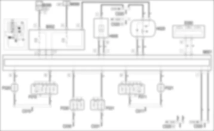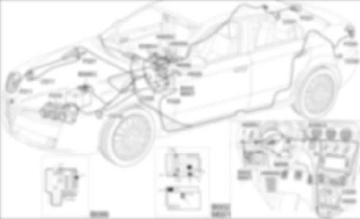

WIRING DIAGRAM - DIRECTION INDICATORS / HAZARD WARNING LIGHTS - Alfa Romeo 159 1.9 JTD 16V Da 01/06
COMPONENTS - DIRECTION INDICATORS / HAZARD WARNING LIGHTS - Alfa Romeo 159 1.9 JTD 16V Da 01/06
| Component code | Description | Reference to the operation |
| B002 | JUNCTION UNIT UNDER DASHBOARD | |
| B099 | MAXIFUSE BOX ON BATTERY | |
| C010 | LEFT FRONT EARTH | - |
| C011 | RIGHT FRONT EARTH | - |
| C020 | PASSENGER SIDE DASHBOARD EARTH | - |
| C030 | LEFT REAR EARTH | - |
| C031 | RIGHT REAR EARTH | - |
| E050 | INSTRUMENT PANEL | |
| F010 | LEFT HEADLAMP | |
| F011 | RIGHT HEADLAMP | |
| F020 | LEFT SIDE REPEATER | |
| F021 | RIGHT SIDE REPEATER | |
| F030 | LEFT REAR LIGHT CLUSTER | |
| F031 | RIGHT REAR LIGHT CLUSTER | |
| H005 | STEERING COLUMN SWITCH UNIT | |
| H020 | HAZARD WARNING LIGHTS SWITCH | |
| M001 | BODY COMPUTER | |
| M089 | STEERING LOCK CONTROL UNIT (NBS) |
COMPONENT LOCATION - DIRECTION INDICATORS / HAZARD WARNING LIGHTS - Alfa Romeo 159 1.9 JTD 16V Da 01/06
| Component code | Description | Reference to the operation |
| B002 | JUNCTION UNIT UNDER DASHBOARD | |
| B099 | MAXIFUSE BOX ON BATTERY | |
| C010 | LEFT FRONT EARTH | - |
| C011 | RIGHT FRONT EARTH | - |
| C020 | PASSENGER SIDE DASHBOARD EARTH | - |
| C030 | LEFT REAR EARTH | - |
| C031 | RIGHT REAR EARTH | - |
| E050 | INSTRUMENT PANEL | |
| F010 | LEFT HEADLAMP | |
| F011 | RIGHT HEADLAMP | |
| F020 | LEFT SIDE REPEATER | |
| F021 | RIGHT SIDE REPEATER | |
| F030 | LEFT REAR LIGHT CLUSTER | |
| F031 | RIGHT REAR LIGHT CLUSTER | |
| H005 | STEERING COLUMN SWITCH UNIT | |
| H020 | HAZARD WARNING LIGHTS SWITCH | |
| M001 | BODY COMPUTER | |
| M089 | STEERING LOCK CONTROL UNIT (NBS) |
DESCRIPTION - DIRECTION INDICATORS / HAZARD WARNING LIGHTS - Alfa Romeo 159 1.9 JTD 16V Da 01/06
The left and right direction indicators are switched on by raising or lowering the special lever on the left of the steering column switch unit; the function is activated with the TEG inserted (ON).The hazard warning lights (left and right direction indicators operated simultaneously) are activated via a button in the centre console next to the gear lever and activates all the direction indicators simultaneously. An LED at the back of the control button also comes on synchronized with the flashing of the exterior lights. This function is always activated for safety reasons.The engagement of the direction indicators / hazard warning lights is managed by the Body Computer which also controls the flashing frequency which is sent to the other nodes via the CAN serial network. In this way the two direction indicator warning lights in the instrument panel are also switched on; in addition, the system provides a low frequency acoustic signal in conjunction with the activation of the lights.The direction indicators check function checks that the lights are working properly: the following are checked for each of the two circuit (right side branch and vehicle left side):- circuit open or bulb missing- short-circuit to earth (bulb s.c. or wiring s.c. to earth)- short circuit to battery voltage (wiring short circuited to Vbatt)When one of the situations described above is ascertained, the Body Computer makes the failure status available to the CAN: in the instrument panel: a special failure warning light comes on and, at the same time, the information is shown in the display only at the key on.In addition, at the same time as a failure warning light comes on, the flashing frequency of the visual indication in the display and the acoustic signal increases; the flashing frequency of the exterior lights and the LED in the emergency button, on the other hand, remains unchanged.
FUNCTIONAL DESCRIPTION - DIRECTION INDICATORS / HAZARD WARNING LIGHTS - Alfa Romeo 159 1.9 JTD 16V Da 01/06
The direction indicator (earth) activation signals are sent to pins 7 of connector I and 30 of connector G of the Body Computer M1 from the steering column switch unit H5.The hazard light activation signal (earth) reaches pin 34 of connector G of M1 from control button H20.The Body Computer M1 receives a specific direct power supply for the hazard warning lights via the line for fuse F53 of the junction unit under the dashboard B; as a result it controls the side direction indicators F20 (left) and F21 (right) from pins 2 of connector A and 22 of connector B, the sid direction indicators F10 (left) and F11 (right) from pins 38 and 39 of connector B and the rear direction indicators F30 (left) and F31 (right) from pins 12 and 3 of connector D.A (positive) signal is sent from pin 29 of connector G of M1 to lightup the LED in the control button H20 with the power supply arriving from the INT line protected by fuse F49 of junciton unit B2.The Body Computer M1 is connected, via the CAN line, to the instrument panel E50 to manage the "direction indicator" warning lights, the buzzer and, if there is a problem in the circuit, the "lights failure" warning light.

 Deutsch
 English
 English
 Español
 Français
 Русский

