 https://portal-diagnostov.com/license.html
Automotive Electricians Portal FZCO
Automotive Electricians Portal FZCO
https://portal-diagnostov.com/license.html
https://portal-diagnostov.com/license.html
Automotive Electricians Portal FZCO
Automotive Electricians Portal FZCO
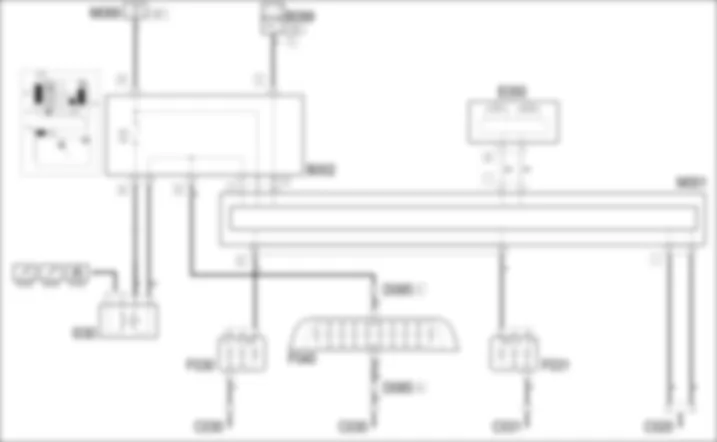
WIRING DIAGRAM - BRAKE LIGHTS - Alfa Romeo 159 2.4 JTD 20V Da 01/06
COMPONENTS - BRAKE LIGHTS - Alfa Romeo 159 2.4 JTD 20V Da 01/06
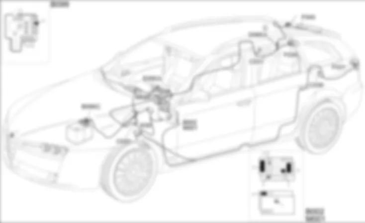
COMPONENT LOCATION - BRAKE LIGHTS - Alfa Romeo 159 2.4 JTD 20V Da 01/06
DESCRIPTION - BRAKE LIGHTS - Alfa Romeo 159 2.4 JTD 20V Da 01/06
The vehicle brake lights are located at the rear in the side lights (by means of a red double filament bulb together with the side light) and in the special centre third brake light mad up of 10 all glass type bulbs.They are operated each time the brake pedal is pressed via the special switch on the actual pedal.767the switch fitted on the pedals consists of two contacts which supply two signals: the first is the N.A. type and recognizes the position of the brake pedal if it is not in the rest postion, i.e. the pedal is pressed; the second is the N.C. type and recognizes the position of the brake pedal in the rest position.The lights are turned on by the N.A. contact (pedal pressed). Information from the N.A. switch is sent in particular to the engine management control unit and the ABS control unit, VDC function.The control function is activated by the TEG inserted enablement signals (INT) and the command from the switch contact.The brake light check function monitors that the side lights are operating correctly: the following are checked:- open circuit (bulb missing or wiring interrupted)- short-circuit to earth (bulb s.c. or wiring s.c. to earth)- short circuit to battery voltage (wiring short circuited to Vbatt)The continuity of the fuse protecting the switch on the brake pedal is also checked.When one of the situations described above is ascertained, the Body Computer makes the failure status available to the CAN: a special "lights failure" warning light comes on in the instrument panel and, at the same time, the information is shown in the display by means of the specific symbol.767the central brake light is controlled directly by the switch on the pedal and is not subject to checking.
FUNCTIONAL DESCRIPTION - BRAKE LIGHTS - Alfa Romeo 159 2.4 JTD 20V Da 01/06
The switch I30 receives an ignition-controlled supply (INT) from the fuse line F37 in the junction unit under the dashboard B2: when the brake pedal is pressed, the N.A. switch closes and sends a signal which "passes through" the junction unit under the dashboard B and reaches the Body Computer M1, pin 2 of connector F.The Body Computer M1 controls the power supply for the brake lights located in the light clusters F30 (left) and F31 (right) from pins 32 and 22 of connector E.The Body Computer M1 is connected via the CAN line to the instrument panel E50 to manage the lights failure warning light and the brake lights check signal if problems are detected in the circuit or in the fuse.The switch I30 controls central brake light F40 directly without any control rules, via the junction unit under the dashboard B2, pin 5 of connector D.


 Deutsch
 English
 English
 Español
 Français
 Русский


