PASSIVE RESTRAINTS
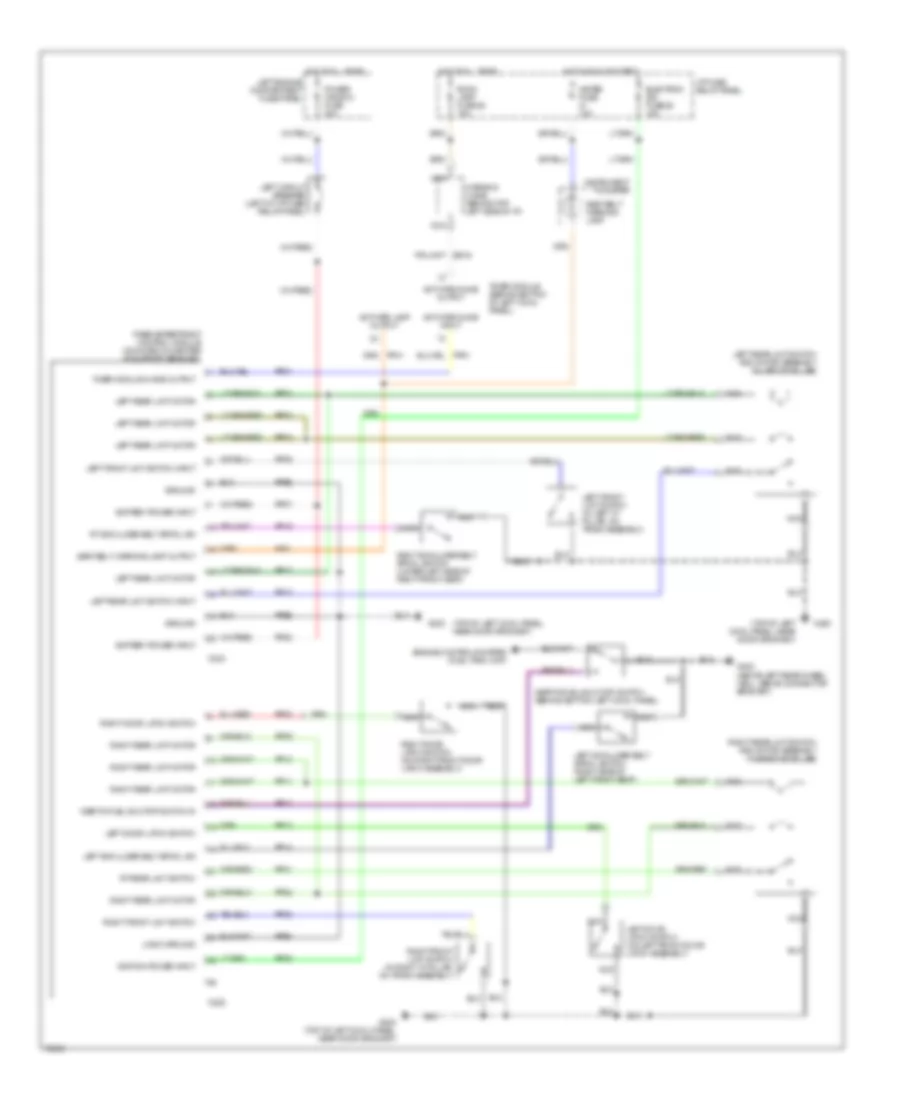
Passive Restraint Wiring Diagram for Mercury Villager GS 1995
List of elements for Passive Restraint Wiring Diagram for Mercury Villager GS 1995:
- (top of left cowl panel, near door grommet)
- Activate chime input
- Activate chime output
- Activate lamp output
- Battery power input
- C223
- C225
- Electron ign fuse 26 10a
- Engine controls system (fuel tank unit)
- G200
- G200 (top of left cowl panel, near door grommet)
- G402 (above left rear wheel well, above connector bracket)
- Ground
- Hot at all times
- Hot in run or start
- I/p fuse/ relay panel
- Ignition power input
- Inertia fuel shut-off switch (behind bottom left cowl panel)
- Inertia fuel shutoff switch in
- Instrument cluster
- Left circuit breaker (left of i/p fuse/ relay panel)
- Left door latch switch
- Left door latch switch (on left front door latch assembly)
- Left engine compartment fuse panel
- Left front limit switch (in left "a" pillar, on track assembly)
- Left front limit switch input
- Left rear limit motor
- Left rear limit switch and motor assembly (in left "b" pillar)
- Left rear limit switch input
- Left shoulder belt spool sw
- Left shoulder belt spool switch (right side of left front seat)
- Logic ground
- Meter fuse 10a
- Nca
- Ni03
- Passive restraint control module (mounted on center i/p support bracket)
- Power window fuse 30a
- Pp01
- Pp02
- Pp03
- Pp04
- Pp05
- Pp07
- Pp08
- Pp09
- Pp10
- Pp11
- Pp12
- Pp13
- Pp14
- Pp15
- Pp17
- Pp18
- Pp20
- Pp21
- Pp22
- Pp23
- Pp25
- Ppe1
- Ppe2
- Ppe3
- Right door latch switch
- Right door latch switch (on right front door latch assembly)
- Right front limit switch
- Right front limit switch (in right "a" pillar, on track assembly)
- Right rear limit motor
- Right rear limit switch and motor assembly (in right "b" pillar)
- Right shoulder belt spool switch (lower left side of right front seat)
- Room lamp fuse 25 15a
- Rt rear limit switch
- Rt shoulder belt spool sw
- Seat belt warning lamp
- Seat belt warning lamp output
- Timer module (behind bottom of left cowl panel)
- Timer module chime output
- Warning chime (behind top left side of i/p)
 English