
 Čeština
 Dansk
Dansk Deutsch
 Ελληνικά
 English
 English
 Español
 Suomi
Suomi Français
 Français
 עברית
עברית Hrvatski
 Magyar
 Italiano
 日本語
日本語 한국어
한국어 Nederlands
 Português
 Português
 Română
 Русский
 Slovenčina
 Slovenščina
 Svenska
 Türkçe
 中文 (中国)

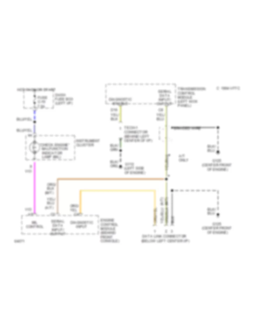
COMPUTER DATA LINES
Data Link Connector Wiring Diagram for Isuzu Trooper SE 1994
List of elements for Data Link Connector Wiring Diagram for Isuzu Trooper SE 1994:

AIR CONDITIONINGCOMPUTER DATA LINESANTI-LOCK BRAKESANTI-THEFTENGINE PERFORMANCECRUISE CONTROLEXTERIOR LIGHTSINSTRUMENT CLUSTERDEFOGGERSPOWER ANTENNAGROUND DISTRIBUTIONINTERIOR LIGHTSHEADLIGHTSPOWER DOOR LOCKSPOWER DISTRIBUTIONHORNPOWER MIRRORSPOWER SEATSSTARTING/CHARGINGPOWER TOP/SUNROOFSHIFT INTERLOCKSRADIOPOWER WINDOWSTRANSMISSIONWARNING SYSTEMSWIPER/WASHER