AIR CONDITIONING
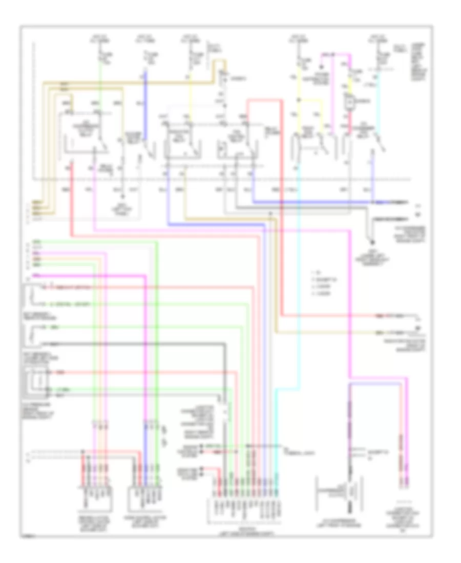
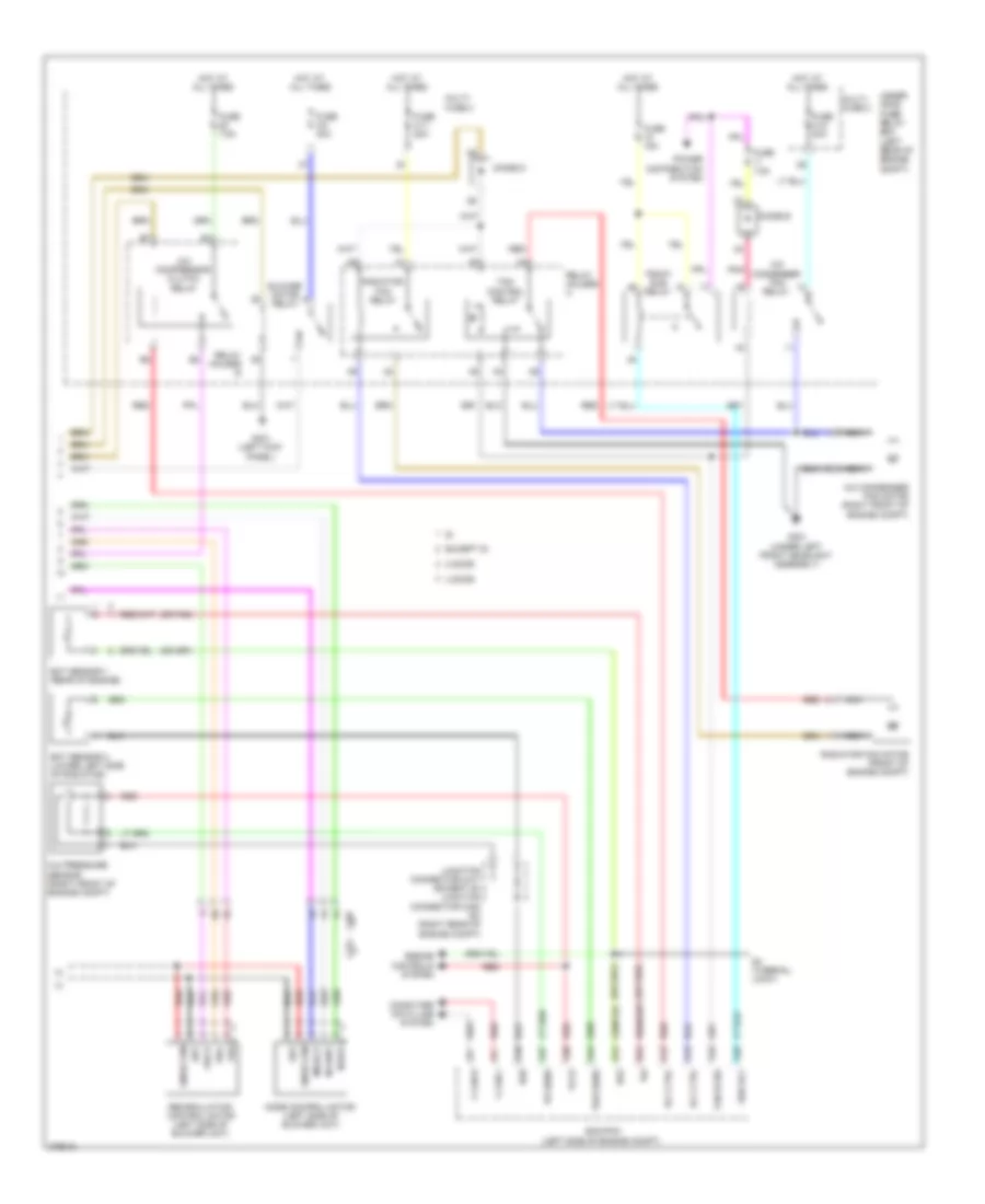
Automatic A/C Wiring Diagram, Except Hybrid (1 of 2) for Honda Civic Si 2012
 https://portal-diagnostov.com/license.html
Automotive Electricians Portal FZCO
Automotive Electricians Portal FZCO
https://portal-diagnostov.com/license.html
https://portal-diagnostov.com/license.html
Automotive Electricians Portal FZCO
Automotive Electricians Portal FZCO
List of elements for Automatic A/C Wiring Diagram, Except Hybrid (1 of 2) for Honda Civic Si 2012:
- 2 door
- 4 door
- Acs
- Air mix control motor (on left side of hvac assembly)
- Amd-p
- Automatic lighting/ sunlight sensor (top center of dash)
- B- canh
- B- canl
- B-canh
- B-canl
- Blower g
- Blower motor (bottom of blower unit)
- Blower v
- C17
- C204
- C207
- C221
- C414
- Center junction box 1
- Center junction box 2
- Climate control unit
- D14
- D17
- Defogger system
- Driver's micu
- Evaporator temperature sensor (top center of hvac unit)
- F/r mtr fresh
- F/r mtr rec
- Fuse 7.5a
- G401 (left kick panel)
- G504 (right end of dash)
- Gauge control module
- Gnd
- H10
- Hot in on
- Hum data
- Humidity sensor
- Humidity/in-car temperature sensor (center of dash)
- Ig2 a/c
- Ill+
- Ill-
- In-car temperature sensor
- Interior lights system
- Junction connector c209 (4 door) junction connector c225 (2 door) (upper center of dash)
- M-cool
- M-hot
- Mdd-p
- Mode mtr def
- Mode mtr vent
- Nca
- Outside air temperature sensor (behind left side of front bumper)
- Pnk
- Power transistor (bottom of blower unit)
- Red
- Rfd-p
- Rr def rly ctrl
- S5v
- Sens com
- Snse com
- Sunlight sensor
- Tam
- Teva
- Tsun
- Under- dash fuse/ relay box (under left end of dash)
- W/ seat heaters
- W/o seat heaters
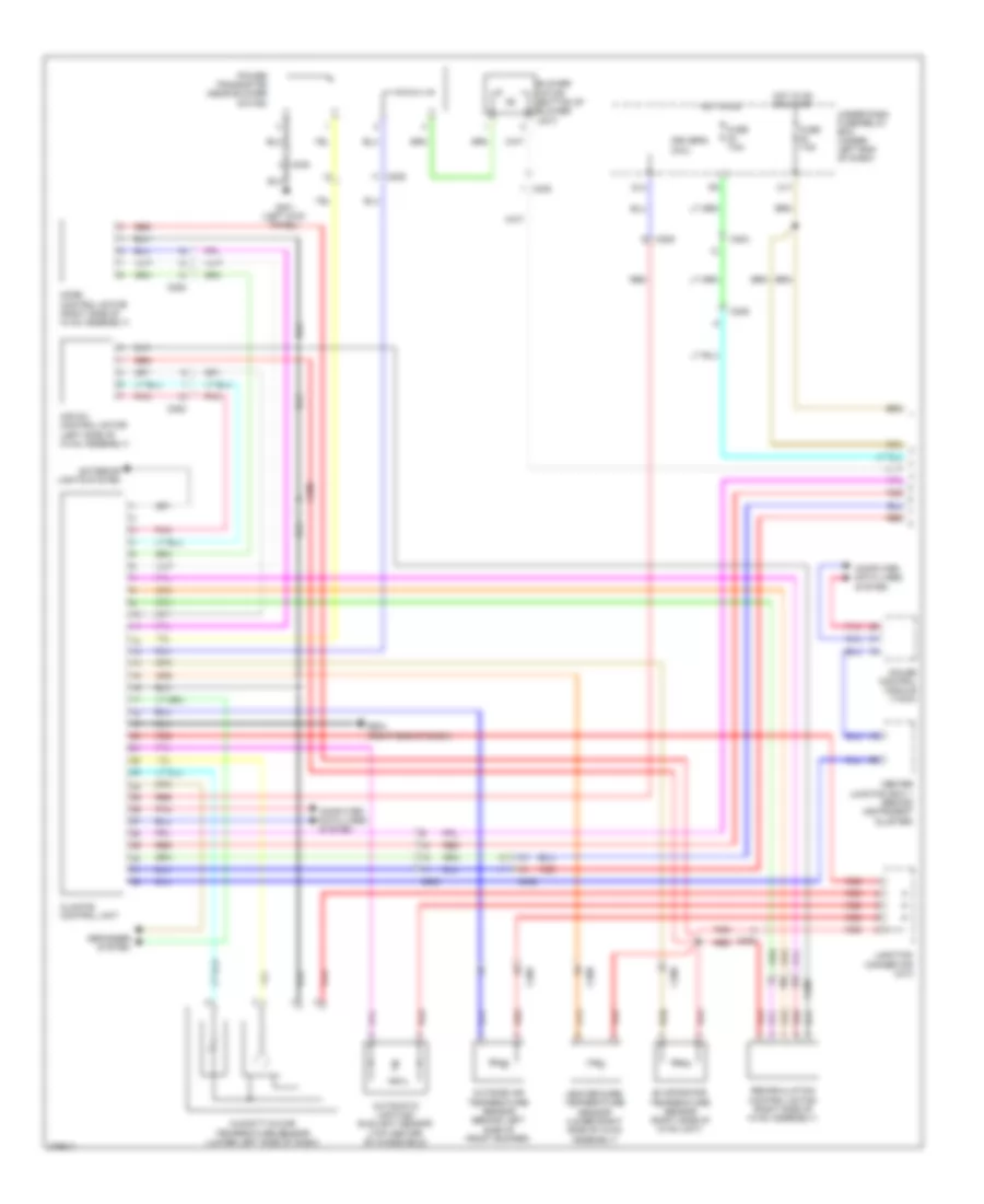
Automatic A/C Wiring Diagram, Except Hybrid (2 of 2) for Honda Civic Si 2012
List of elements for Automatic A/C Wiring Diagram, Except Hybrid (2 of 2) for Honda Civic Si 2012:
- (or pnk)
- 2 door
- 4 door
- A/c compressor (left front of engine)
- A/c compressor clutch
- A/c compressor clutch relay
- A/c condenser fan motor (right front of engine compt)
- A/c condenser fan relay
- A/c pressure sensor (right front of engine compt)
- A10
- A11
- A12
- A15
- A16
- A20
- A27
- A30
- A44
- B13
- B34
- B44
- Blower motor relay
- C207
- C221
- Computer data line system
- Diode d
- Diode e
- Ecm/pcm (left side of engine compt)
- Ect sensor 1 (rear of engine)
- Ect sensor 2 (lower left side of radiator)
- Engine controls system
- Except si
- F can-h
- F can-l
- Fan control relay
- Fan hi sig
- Frd-p
- Frs
- Fuse 15a
- Fuse 2-10 20a
- Fuse 2-11 20a
- Fuse 2-8 40a
- Fuse 7.5a
- G301 (under left front headlight assembly)
- G401 (left kick panel)
- Hot at all times
- Junction connector c404 (except si) junction connector c410 (si)
- Junction connector c417 (except si) junction connector c420 (si) (right rear of engine compt)
- M-def
- M-vent
- Mode control motor (left side of blower unit)
- Mode-p
- Multi- fuse 2
- Nca
- Pd sens
- Pgm-fi sub relay
- Pnk
- Power distribution system
- Radiator fan motor (front of engine compt)
- Radiator fan relay
- Rec
- Recirculation control motor (left side of blower unit)
- Red
- Relay holder a
- Relay holder b
- Rly ctrl
- S4 (thermal joint)
- S5v
- Sg2
- Sg6
- Snse com
- Sub rly
- Tw2 sens
- Under- hood fuse/ relay box (left rear of engine compt)
- Vcc6
Automatic A/C Wiring Diagram, Hybrid (1 of 2) for Honda Civic Si 2012
List of elements for Automatic A/C Wiring Diagram, Hybrid (1 of 2) for Honda Civic Si 2012:
- Air mix control motor (left side of hvac assembly)
- Automatic lighting/ sunlight sensor (top center of windshield)
- Blower motor (bottom of blower unit)
- C17
- C204
- C205
- C206
- C208
- C228
- C402
- C408
- Center junction box 1 (behind instrument cluster)
- Climate control unit
- Computer data lines system
- D14
- Defogger system
- Driver's micu
- Evaporator
- Exterior lights system
- Fuse 7.5a
- G401 (left kick panel)
- G504 (right end of dash)
- Gauge control module (tach)
- Heater core temperature sensor (lower right side of hvac assembly)
- Hot in on
- Hot in on or start
- Humidity/in-car temperature sensor (lower left side of dash)
- Junction connector c213
- Mode control motor (right side of hvac assembly)
- Outside air temperature sensor (behind left side of front bumper)
- Pnk
- Power transistor (near blower motor)
- Recirculation control motor (right side of hvac assembly)
- Red
- Temperature sensor (right side of hvac unit)
- Under-dash fuse/relay box (under left end of dash)
Automatic A/C Wiring Diagram, Hybrid (2 of 2) for Honda Civic Si 2012
List of elements for Automatic A/C Wiring Diagram, Hybrid (2 of 2) for Honda Civic Si 2012:
- A/c compressor (left front of engine)
- A/c compressor clutch relay
- A/c compressor driver (right side of battery module)
- A/c condenser fan motor (right front of engine compt)
- A/c condenser fan relay
- A/c pressure sensor (right front corner of engine compt)
- A10
- A11
- A12
- A15
- A16
- A20
- A27
- A30
- A44
- Auxiliary electric water pump (right rear of engine compt)
- Auxiliary electric water pump relay
- B10
- B34
- B44
- Blower motor relay
- C402
- Clutch compressor a/c
- Computer data line system
- Computer data lines system
- Diode a
- Diode b
- Ect sensor 1 (right rear of engine)
- Ect sensor 2 (lower left side of radiator)
- Engine controls system
- Fan control relay
- Fuse 15a
- Fuse 2-10 20a
- Fuse 2-11 20a
- Fuse 2-8 40a
- Fuse 7.5a
- G301 (under left headlight assembly)
- G401 (left kick panel)
- G901 (base of right "c" pillar)
- Hot at all times
- Junction connector c409
- Junction connector c602
- Nca
- Pcm (left side of engine compt)
- Pgm-fi sub relay
- Pnk
- Radiator fan motor (behind radiator)
- Radiator fan relay
- Red
- Relay control module (in under-hood fuse/relay box)
- Thermal protector
- Under-hood fuse/relay box (left rear of engine compt)
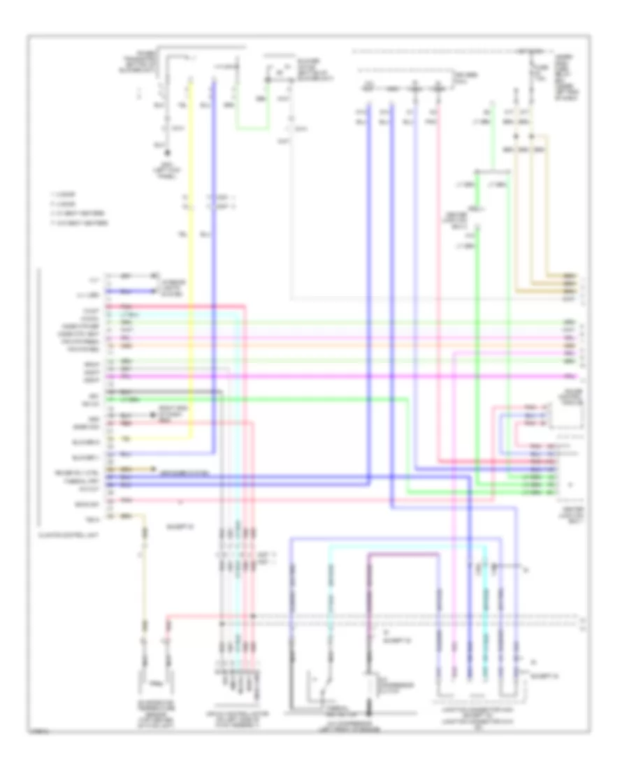
Manual A/C Wiring Diagram, Except Hybrid (1 of 2) for Honda Civic Si 2012
List of elements for Manual A/C Wiring Diagram, Except Hybrid (1 of 2) for Honda Civic Si 2012:
- (or pnk)
- (right end of dash) g504
- 2 door
- 4 door
- A/c compressor (left front of engine)
- A/c compressor clutch
- A/c out
- A11
- A12
- A13
- Acs
- Air mix control motor (on left side of hvac assembly)
- Amd-p
- B- canh
- B- canl
- B11
- B12
- B13
- Blower g
- Blower motor (bottom of blower unit)
- Blower v
- C17
- C204
- C207
- C221
- C409
- C414
- Center junction box 1
- Center junction box 2
- Climate control unit
- D14
- D17
- Defogger system
- Driver's micu
- Econ sw
- Evaporator temperature sensor (top center of hvac unit)
- Except si
- F/r mtr fresh
- F/r mtr rec
- Fuse 7.5a
- G401 (left kick panel)
- Gauge control module
- Gnd
- H10
- Hot in on
- Ig2 a/c
- Ill+
- Ill- (led)
- Interior lights
- Junction connector c404 (except si) junction connector c410 (si)
- M-cool
- M-hot
- Mdd-p
- Mode mtr def
- Mode mtr vent
- Nca
- Pnk
- Power transistor (bottom of blower unit)
- Red
- Rfd-p
- Rr def rly ctrl
- S5v
- Snse com
- Snsr com
- System
- Teva
- Thermal protector
- Thermal prt
- Under- dash fuse/ relay box (under left end of dash)
- W/ seat heaters
- W/o seat heaters
- W12
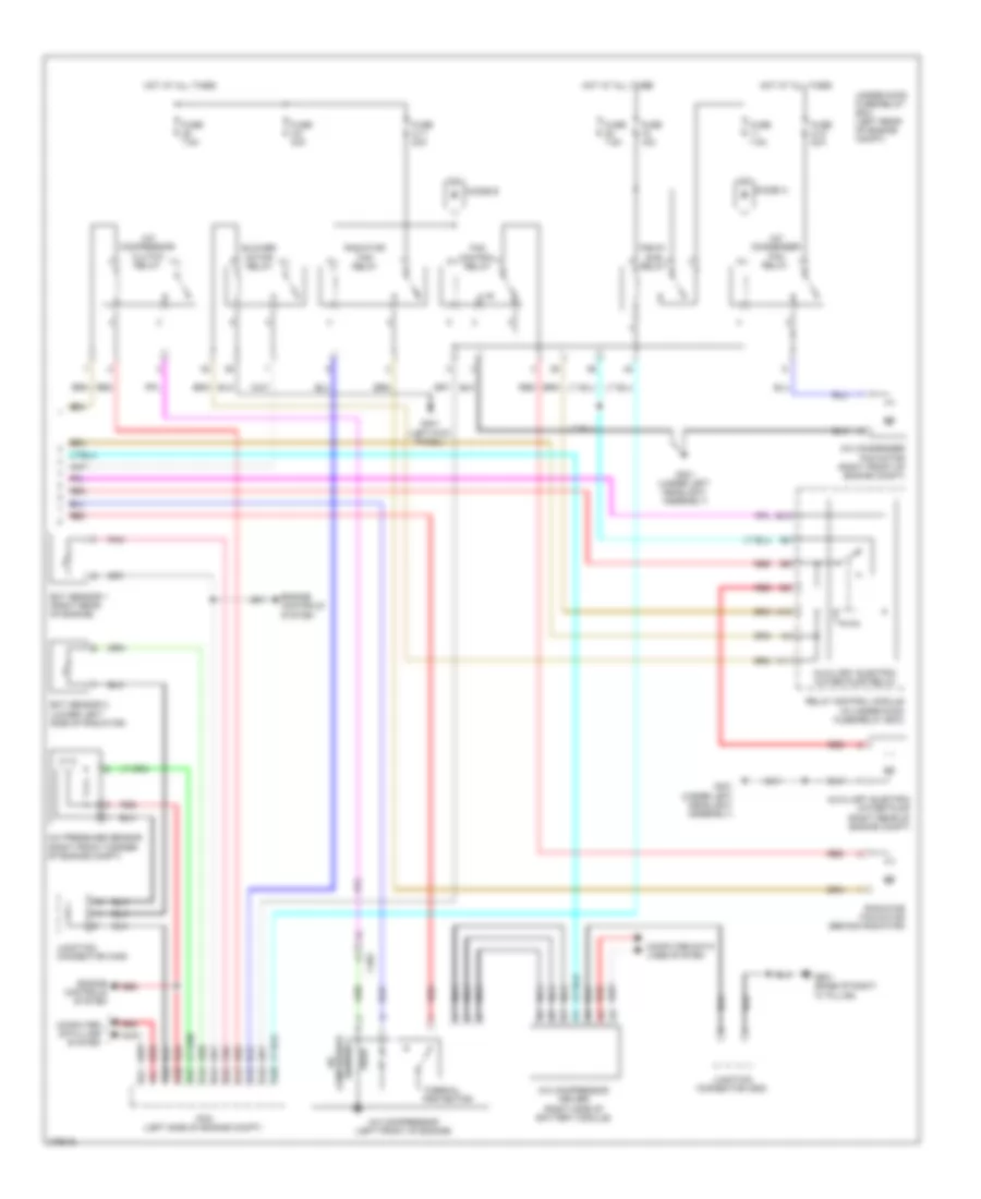
Manual A/C Wiring Diagram, Except Hybrid (2 of 2) for Honda Civic Si 2012
List of elements for Manual A/C Wiring Diagram, Except Hybrid (2 of 2) for Honda Civic Si 2012:
- (or pnk)
- 2 door
- 4 door
- A/c compressor clutch relay
- A/c condenser fan motor (right front of engine compt)
- A/c condenser fan relay
- A/c pressure sensor (right front of engine compt)
- A10 sg6
- A12 rly ctrl
- A15 rly ctrl
- A16 fan hi sig
- A20 sub rly
- A27 pd sens
- A3 f can-h
- A30 vcc6
- A4 f can-l
- A44 tw2 sens
- B34 tw
- B44 sg2
- Blower motor relay
- C207
- C221
- Computer data line system
- Diode d
- Diode e
- Ecm/pcm (left side of engine compt)
- Ect sensor 1 (rear of engine)
- Ect sensor 2 (lower left side of radiator)
- Engine controls system
- Except si
- Fan control relay
- Frd-p
- Frs
- Fuse 15a
- Fuse 2-10 20a
- Fuse 2-11 20a
- Fuse 2-8 40a
- Fuse 7.5a
- G301 (under left front headlight assembly)
- G401 (left kick panel)
- Hot at all times
- Junction connector c417 (except si) junction connector c420 (si) (right rear of engine compt)
- M-def
- M-vent
- Mode control motor (left side of blower unit)
- Mode-p
- Multi- fuse 2
- Nca
- Pgm-fi sub relay
- Pnk
- Power distribution system
- Radiator fan motor (front of engine compt)
- Radiator fan relay
- Rec
- Recirculation control motor (left side of blower unit)
- Red
- Relay holder a
- Relay holder b
- S4 (thermal joint)
- S5v
- Snse com
- Under- hood fuse/ relay box (left rear of engine compt)

 Čeština
 Dansk
Dansk Deutsch
 Ελληνικά
 English
 English
 Español
 Suomi
Suomi Français
 Français
 עברית
עברית Hrvatski
 Magyar
 Italiano
 日本語
日本語 한국어
한국어 Nederlands
 Português
 Português
 Română
 Русский
 Slovenčina
 Slovenščina
 Svenska
 Türkçe
 中文 (中国)