ELECTRONIC POWER STEERING
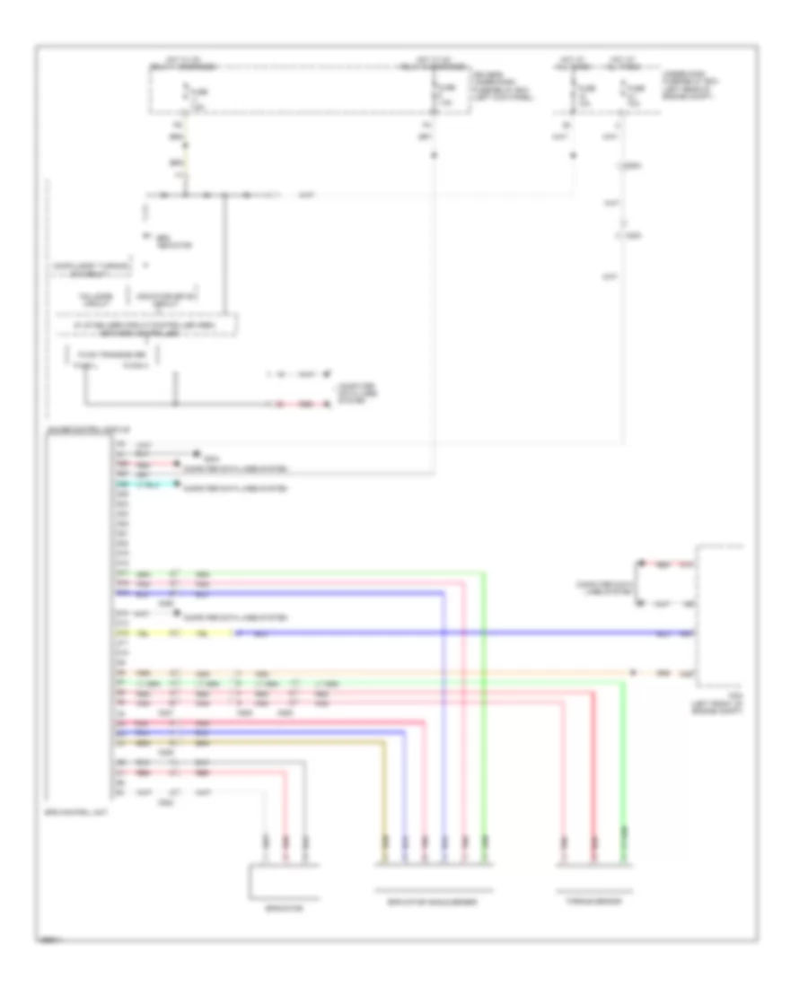
Electronic Power Steering Wiring Diagram for Honda Crosstour EX 2013
List of elements for Electronic Power Steering Wiring Diagram for Honda Crosstour EX 2013:
- 5v stabilizer circuit/controller area
- A10
- A39
- A40
- C202
- C203
- C206
- C207
- C504
- C505
- C508
- Compulsory turning
- Computer data lines system
- D10
- D11
- D12
- D13
- D14
- D15
- D16
- D17
- D18
- D19
- D20
- D21
- D22
- D23
- D24
- D25
- D26
- D27
- D28
- Driver's under-dash fuse/relay box (left kick panel)
- Eps control unit
- Eps indicator
- Eps motor
- Eps motor angle sensor
- F-can h
- F-can l
- F-can transceiver
- Fail-safe circuit
- Fuse 10a
- Fuse 2-1 70a
- Fuse 7.5a
- G204
- Gauge control module
- Hot at all times
- Hot w/ ig1 relay 1 energized
- Hot w/ ig1 relay 2 energized
- Indicator drive circuit
- Network controller
- On circuit
- Pcm (left front of engine compt)
- Pnk
- Red
- Torque sensor
- Under-hood fuse/relay box (left rear of engine compt)
 Čeština
 Dansk
Dansk Deutsch
 Ελληνικά
 English
 English
 Español
 Suomi
Suomi Français
 Français
 עברית
עברית Hrvatski
 Magyar
 Italiano
 日本語
日本語 한국어
한국어 Nederlands
 Português
 Português
 Română
 Русский
 Slovenčina
 Slovenščina
 Svenska
 Türkçe
 中文 (中国)
 Polski