ANTI-LOCK BRAKES
Anti-lock Brakes Wiring Diagram, with Vehicle Dynamics Integrated Management (1 of 3) for Lexus IS 350 2008


List of elements for Anti-lock Brakes Wiring Diagram, with Vehicle Dynamics Integrated Management (1 of 3) for Lexus IS 350 2008:
- A1 (left rear of engine compt)
- A3 (left rear of engine compt)
- A33
- A35
- Abs 1 fuse 50a
- Abs 3 fuse 25a
- Abs mtr1 relay
- Abs mtr2 relay
- Abs sol relay
- Ast
- Brake pedal load sensing switch (under left side of dash)
- Canh
- Canl
- Computer data lines system
- Csw
- D/g
- Data line computer
- Data link connector 3 (behind lower left side of dash)
- Engine room r/b 1 (right rear of engine compt)
- Engine room r/b 3 (left rear of engine compt)
- Fl+
- Fl-
- Fla+
- Fla-
- Flo
- Fr+
- Fr-
- Fra+
- Fra-
- Fro
- Fss
- Fsw+
- Gnd2
- Grd1
- Grd3
- Headlamp swivel ecu (left kick panel)
- Hot at all times
- Ig1
- J/c a15
- J/c a29 (at left kick panel)
- J/c a33 & j80 (at right kick panel)
- J4 (right kick panel)
- J77
- J78
- J80
- Left front speed sensor (on left front wheel)
- Left rear speed sensor (on left rear wheel)
- Mpx-b fuse 10a
- Mpx1
- Mpx2
- Mrf
- Nca
- Pkb
- Pmc
- Pnk
- Red
- Right front speed sensor (on right front wheel)
- Right rear speed sensor (on right rear wheel)
- Rl+
- Rl-
- Rla+
- Rla-
- Rr+
- Rr-
- Rra+
- Rra-
- Sel2
- Sflr
- Sfrr
- Sil
- Skid control ecu (behid right side of dash)
- Sm1+
- Sm1-
- Sm2+
- Sm2-
- Sp1
- Spdl
- Spdr
- Srlr
- Srrr
- Ssel
- Stp1
- Stp2
- Stpo
- System
- Traction control switch
- Vcm
- Wfse
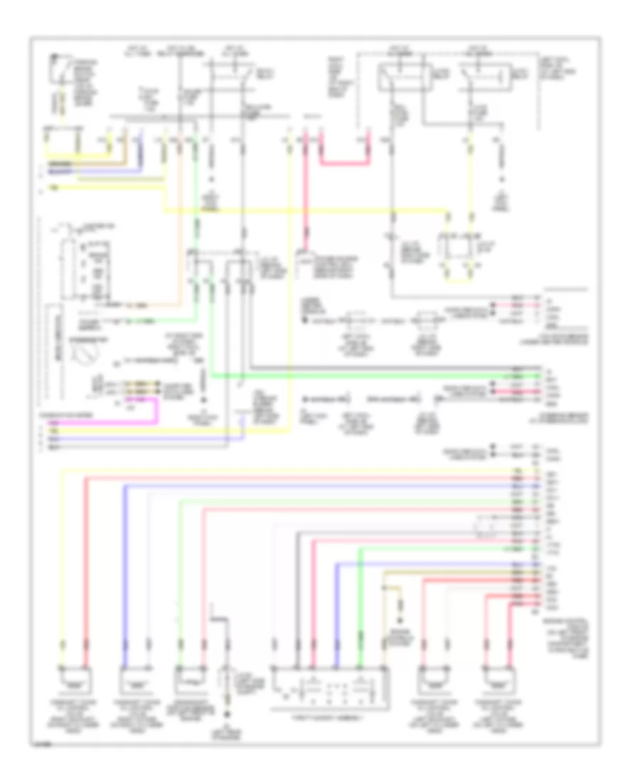
Anti-lock Brakes Wiring Diagram, with Vehicle Dynamics Integrated Management (2 of 3) for Lexus IS 350 2008
List of elements for Anti-lock Brakes Wiring Diagram, with Vehicle Dynamics Integrated Management (2 of 3) for Lexus IS 350 2008:
- (behind left side of dash) stop lamp control relay
- (behind left side of dash) vsc warning buzzer
- (left rear rear engine compt) a2
- (left side of engine compt)
- (near top of parking brake lever)
- A10
- A24
- A25
- A3 (left rear of engine compt)
- Abs ind
- Brake actuator (left rear of engine compt)
- Brake ind
- Brake lamp relay
- Circuit input
- Combination meter
- Computer data lines system
- D12 pnk
- D6 pnk
- E2b
- E2c
- Ecu-ig rh fuse 10a
- Engine room r/b 2 (left side of engine compt)
- Fla+
- Fla-
- Fra+
- Fra-
- Gauge fuse 7.5a
- Grd
- Hot at all times
- Hot w/ ig2 relay energized
- Ig+
- Ig1d
- J/c a20 (upper left kick panel)
- J/c a9
- J/c j27 (behind left side of dash)
- J/c j70 (behind right side of dash)
- J2 (under center console)
- J34
- J4 (right kick panel)
- L10
- Left cowl side j/b (at left end of dash)
- Master ind
- Micro computer
- Mpx+
- Mpx-
- Nca
- Parking brake switch
- Pmc
- Pnk
- Power source control ecu (behind right side of dash)
- Red
- Rh-ig 1 ig1 relay
- Right cowl side j/b (at right end of dash)
- Rla+
- Rla-
- Rra+
- Rra-
- Sel2
- Sflr
- Sfrr
- Slip ind
- Sm1+
- Sm1-
- Sm2+
- Sm2-
- Speedometer
- Srlr
- Srrr
- Ssel
- Stop lamp switch (above brake pedal, on bracket)
- Stop sw fuse 7.5a
- Vcm
- Vcs off ind
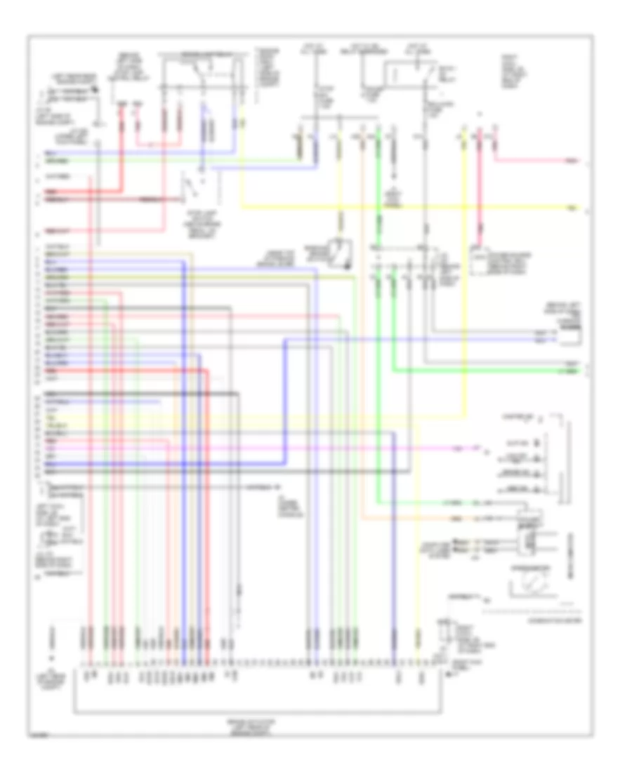
Anti-lock Brakes Wiring Diagram, with Vehicle Dynamics Integrated Management (3 of 3) for Lexus IS 350 2008
List of elements for Anti-lock Brakes Wiring Diagram, with Vehicle Dynamics Integrated Management (3 of 3) for Lexus IS 350 2008:
- Bat
- Camshaft timing oil control valve (left exhaust) (on left cylinder head)
- Camshaft timing oil control valve (left intake) (on left cylinder head)
- Camshaft timing oil control valve (right exhaust) (on right cylinder head)
- Camshaft timing oil control valve (right intake) (on right cylinder head)
- Canh
- Canl
- Computer data lines system
- Crankshaft position sensor (on left front of engine)
- D12
- D13
- D29
- E1 (left rear of engine)
- Ecu-ig rh fuse 10a
- Engine control module (on left front of engine compartment, in protective case)
- Ess
- Eta
- Ge0
- Gnd
- Hot at all times
- J/c 27 (behind left side of dash)
- J/c a7 & a8
- J/c e1 (left side of engine compt)
- J/c j70 (behind right side of dash)
- J1 (left kick panel)
- J2 (under center console)
- Left cowl side j/b (at left end of dash)
- Left ig2 relay
- Lh- ig 1 relay
- Lh-ig fuse 10a
- Nca
- Ne+
- Ne-
- Oc1+
- Oc1-
- Oc2+
- Oc2-
- Oe1+
- Oe1-
- Oe2+
- Oe2-
- Pnk
- Red
- Seat belt control ecu (left side of trunk)
- Steering sensor (at steering column)
- Throttle body assembly
- Vcta
- Vta1
- Vta2
- Yaw rate sensor (under center console)
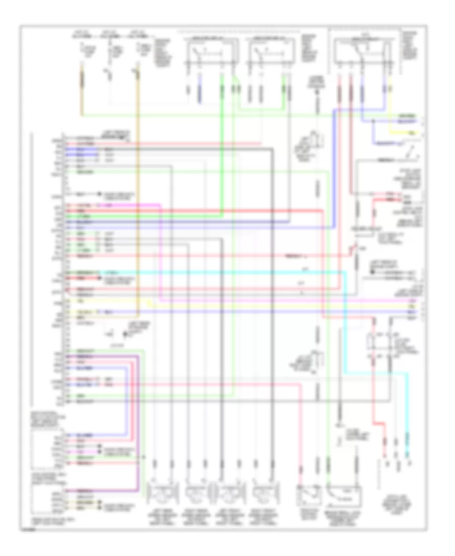
Anti-lock Brakes Wiring Diagram, without Vehicle Dynamics Integrated Management (1 of 2) for Lexus IS 350 2008
List of elements for Anti-lock Brakes Wiring Diagram, without Vehicle Dynamics Integrated Management (1 of 2) for Lexus IS 350 2008:
- (a/t)
- (left rear of engine compt) a1
- (left rear of engine compt) a2
- (left rear of engine compt) a3
- (under center console) j2
- +bs
- 4wd control ecu (if equipped) (right kick panel)
- A/t
- A29
- A33
- Abs 1 fuse 50a
- Abs 2 fuse 30a
- Abs mtr1 relay
- Abs mtr2 relay
- Brake pedal load sensing switch (under left side of dash)
- Brk-lp relay
- Canh
- Canl
- Computer data lines system
- Csw
- D/g
- Data link connector 3 (behind lower left side of dash)
- E2b
- E2c
- Engine room r/b 1 (right rear of engine compt)
- Engine room r/b 2 (left side of engine compt)
- Engine room r/b 3 (left rear of engine compt)
- Fl+
- Fl-
- Flo
- Fr+
- Fr-
- Fro
- Fsw+
- Gnd1
- Gnd2
- Headlamp swivel ecu (left kick panel)
- Hot at all times
- Ig1
- J/c a15
- J/c a20 (upper left kick panel)
- J/c a29 & j10 (at left kick panel)
- J/c a33 & j80 (at right kick panel)
- J/c a9 (left side of engine compt)
- J/c j70 (behind right side of dash)
- J10
- J80
- Left cowl side j/b (at left end of dash)
- Left front speed sensor (on left front wheel)
- Left rear speed sensor (on left rear wheel)
- M/t
- Mpx-b fuse 10a
- Mpx1
- Mpx2
- Mrf
- Pkb
- Pnk
- Red
- Right front speed sensor (on right front wheel)
- Right rear speed sensor (on right rear wheel)
- Rl+
- Rl-
- Rlo
- Rr+
- Rr-
- Rro
- Sil
- Skid control ecu w/ actuator (left rear of engine compt)
- Sp1
- Spdl
- Spdr
- Stop lamp control relay (a/t) (behind left side of dash)
- Stop lamp switch (above brake pedal, on bracket)
- Stp1
- Stp2
- Stpo
- Traction control switch
- Wfse
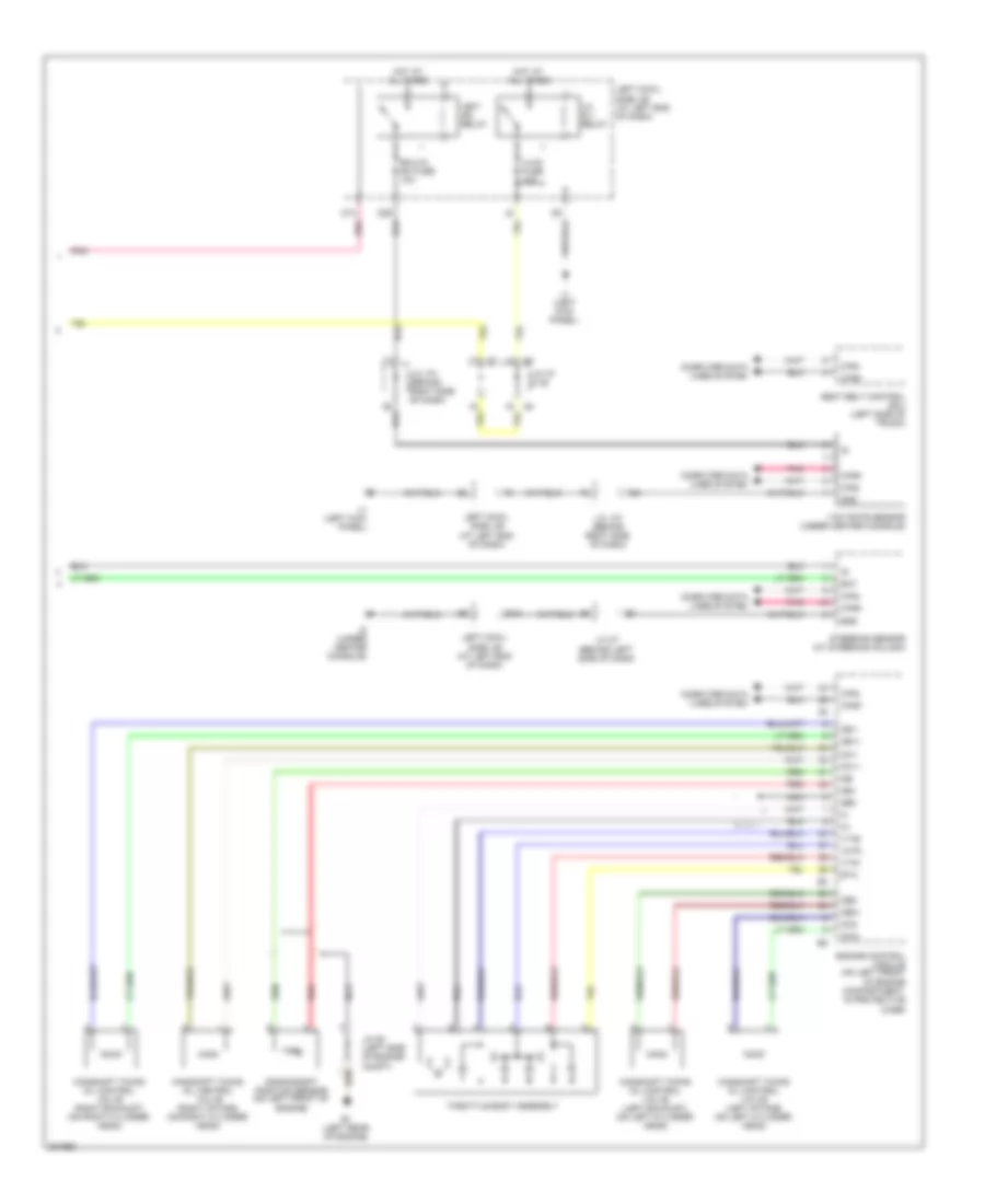
Anti-lock Brakes Wiring Diagram, without Vehicle Dynamics Integrated Management (2 of 2) for Lexus IS 350 2008
List of elements for Anti-lock Brakes Wiring Diagram, without Vehicle Dynamics Integrated Management (2 of 2) for Lexus IS 350 2008:
- (at right end of dash) right cowl side j/b
- (under center console) j2
- A/t
- A10
- A12
- A24
- A25
- Abs ind
- Bat
- Brake ind
- Camshaft timing oil control valve (left exhaust) (on left cylinder head)
- Camshaft timing oil control valve (left intake) (on left cylinder head)
- Camshaft timing oil control valve (right exhaust) (on right cylinder head)
- Camshaft timing oil control valve (right intake) (on right cylinder head)
- Canh
- Canl
- Combination meter
- Computer data lines system
- Crankshaft position sensor (on left front of engine)
- D12
- D13
- D14
- D29
- E1 (left rear of engine)
- Ecu ig rh fuse 10a
- Ecu-ig rh fuse 10a
- Engine control module (on left front of engine compartment, in protective case)
- Engine controls system
- Ess
- Gauge fuse 7.5a
- Geo1
- Gnd
- Hot at all times
- Hot w/ ig2 relay energized
- Ig+
- Ig1d
- Input circuit
- J/c a7 & a8
- J/c e1 (left side of engine compt)
- J/c j27 (behind left side of dash)
- J/c j70 (behind right side of dash)
- J1 (left kick panel)
- J2 (left kick panel)
- J34
- J4 (right kick panel)
- L10
- Left cowl side j/b (at left end of dash)
- Lh-ig 1 relay
- Lh-ig 2 relay
- Lh-ig fuse 10a
- M/t
- Master ind
- Micro computer
- Mpx+
- Mpx-
- Nca
- Ne+
- Ne-
- Oc1+
- Oc1-
- Oc2+
- Oc2-
- Oe1+
- Oe1-
- Oe2+
- Oe2-
- Parking brake switch (near top of parking brake lever)
- Pnk
- Power source control ecu (behind right side of dash)
- Red
- Rh-ig 1 relay
- Right cowl side j/b (at right end of dash)
- Slip ind
- Speedometer
- Steering sensor (at steering column)
- Stop sw fuse 7.5a
- Throttle body assembly
- Vc2
- Vsc off ind
- Vsc warning buzzer (behind left side of dash)
- Vta1
- Vta2
- Yaw rate sensor (under center console)

 Čeština
 Dansk
Dansk Deutsch
 Ελληνικά
 English
 English
 Español
 Suomi
Suomi Français
 Français
 עברית
עברית Hrvatski
 Magyar
 Italiano
 日本語
日本語 한국어
한국어 Nederlands
 Português
 Português
 Română
 Русский
 Slovenčina
 Slovenščina
 Svenska
 Türkçe
 中文 (中国)