БЛОК ПРЕДОХРАНИТЕЛЕЙ И РЕЛЕ
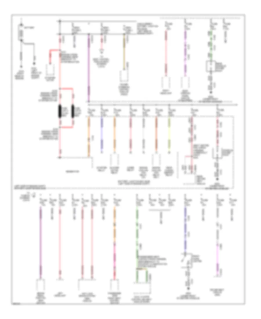
Электросхема блока предохранителей и реле (1 из 5) для Lincoln MKS 2013
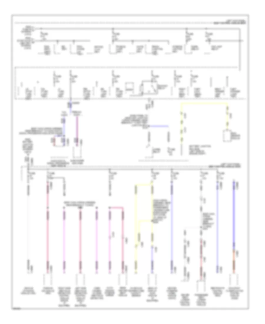
Электросхема блока предохранителей и реле (1 из 5) для Lincoln MKS 2013 - Список элементов:
- (left side of engine compt) battery junction box (bjb)
- (not used)
- (seat heated pad wiring harness, in breakout c3047) s333
- Anti-lock brake system (abs) module
- Battery
- Battery junction box (bjb) (left side of engine compt)
- Blower motor relay
- Brake pedal position (bpp) switch
- C144
- C1467b
- C1617a
- C1617b
- C1617c
- C1617d
- C210
- C211
- C214
- C219
- C3047
- C3265a
- C3304b
- C3381
- C3382
- C341a
- Console power point
- Driver seat module (dsm)
- Dual climate controlled seat module (dcsm)
- Engine cooling fan relay hfc 1
- Engine cooling fan relay lfc
- Front cigar lighter
- Fuse 10a
- Fuse 15a
- Fuse 20a
- Fuse 30a
- Fuse 40a
- Fuse 50a
- Fuse link a (10 ga- red)
- Fuse link b (10 ga- red)
- G103 (left front of engine compt)
- G104 (right rear of engine)
- G200 (under front of center console)
- Generator
- High current battery junction box (bjb) (left side of engine compt)
- Left headlamp
- Mega fuse 1 100a
- Mega fuse 2 60a
- Mega fuse 4 100a
- Near breakout to occupant classification system module) s341
- Passenger side front seat control switch
- Power steering control module (pscm)
- Rear console power point
- Rear heated seat module
- Rear window defrost relay
- Red
- Right headlamp
- Roof opening panel module (if equipped)
- S127 (engine wiring harness, near breakout to starter motor)
- S128 (engine wiring harness, near breakout to starter motor)
- S129 (engine wiring harness, near breakout to red starter motor)
- Starter motor
- Starter relay
- To body control module (bcm) (diagram 3 of 5)
- To fuse 62 (diagram 2 of 5)
- Wiper relay
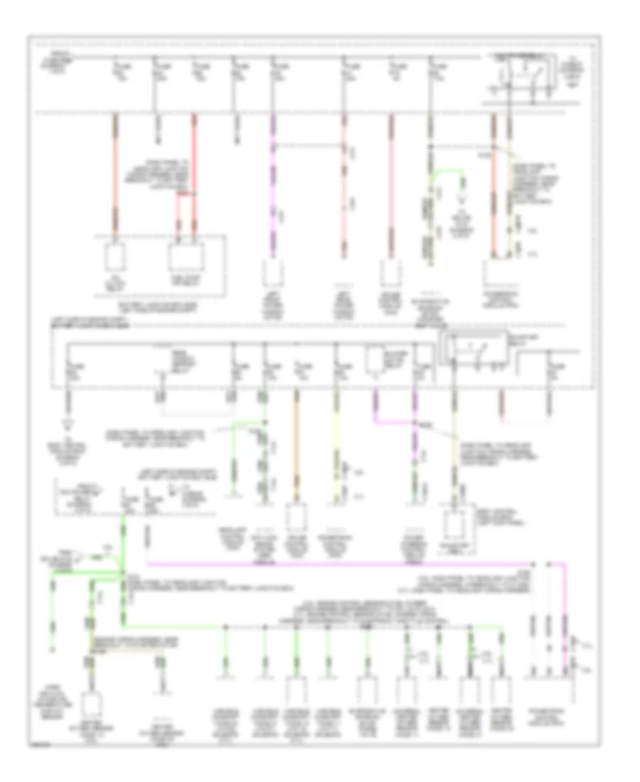
Электросхема блока предохранителей и реле (2 из 5) для Lincoln MKS 2013
Электросхема блока предохранителей и реле (2 из 5) для Lincoln MKS 2013 - Список элементов:
- (3.5l: engine control sensor & fuel charge wiring harness, near breakout to coil on plug 3) (3.7l: engine control sensor & fuel charge wiring harness, near breakout to electronic throttle control)
- (dash panel to headlamp junction wiring harness, near breakout to battery junction box)
- (dash panel to headlamp junction wiring harness, near breakout to battery junction box) s121
- (engine wiring harness, near breakout to starter motor) s168
- (left side of engine compt) battery junction box (bjb)
- (not used)
- 3.5l
- 3.7l
- A/c clutch relay
- Anti-lock brake system (abs) module
- Battery junction box (bjb) (left side of engine compt)
- Blower motor relay
- Body control module (bcm) (left kick panel)
- C134
- C1381b
- C144
- C1467a
- C175b
- C211
- C2280f
- C311
- C313
- C315
- Cruise control module (ccm)
- Evaporative emission (evap) canister vent valve
- Evaporative emission (evap) purge valve
- From fuse 59 b (diagram 1 of 5)
- From pcm power d relay (diagram 2 of 5)
- From splice s135 c (diagram 2 of 5)
- Fuel pump (fp) relay
- Fuse 10a
- Fuse 15a
- Fuse 20a
- Fuse 30a
- Fuse 5a
- Fuse 7.5a
- Headlamp control module (hcm)
- Heated oxygen sensor (ho2s) 12
- Heated oxygen sensor (ho2s) 12 (3.5l)
- Heated oxygen sensor (ho2s) 22
- Heated oxygen sensor (ho2s) 22 (3.5l)
- Left front power window motor
- Left rear power window motor
- Mass air flow/ intake air temperature (maf/iat) sensor
- Nca
- Pcm power relay
- Power steering control module (pscm)
- Powertrain control module (pcm)
- Rear window defrost relay
- Red
- Run/start (fet)
- Run/start relay
- S135
- S139
- S146
- S159 (3.5l: dash panel to headlamp junction wiring harness, in breakout to c1100d) (3.7l: dash panel to headlamp wiring harness)
- To body control module (bcm) (diagram 5 of 5)
- To fuse 67 (diagram 2 of 5)
- To fuse 68 (diagram 3 of 5)
- To splice s134 (diagram 2 of 5)
- Universal heated oxygen sensor (ho2s) 11
- Universal heated oxygen sensor (ho2s) 21
- Variable camshaft timing 11 (vct11) solenoid
- Variable camshaft timing 12 (vct12) solenoid (3.7l)
- Variable camshaft timing 21 (vct21) solenoid
- Variable camshaft timing 22 (vct22) solenoid (3.7l)
- Wiring harness, near breakout to battery junction box)
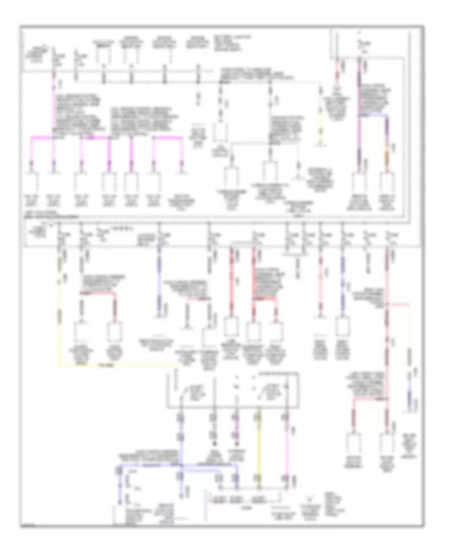
Электросхема блока предохранителей и реле (3 из 5) для Lincoln MKS 2013
Электросхема блока предохранителей и реле (3 из 5) для Lincoln MKS 2013 - Список элементов:
- (3.5l: engine control sensor & fuel charge wiring harness, near breakout to knock sensor) (3.7l: engine control sensor & fuel charge wiring harness, near breakout to electronic throttle control) s147
- (body main wiring harness, near breakout to g302) s364
- (dash panel to headlamp junction wiring harness, near breakout to battery junction box) s122
- (engine control sensor & fuel charge wiring harness, near breakout to coil on plug 3) s150
- (left front door window regulator wiring harness, near breakout to master window adjust switch) s502
- (left kick panel) body control module (bcm)
- (main wiring harness, near breakout to accessory protocol interface module) s242
- (main wiring harness, near breakout to passenger's temperature blend door actuator) s237
- (main wiring harness, near breakout to passenger's temperature blend door actuator) s239
- (main wiring harness, near breakout to steering column tilting motor) s246
- (main wiring harness, near breakout to steering column tilting motor) s247
- (not used)
- 3.5l
- 3.7l
- 4x4 control module
- A/c clutch relay
- Accessory protocol interface module (apim)
- Active grille shutter (ags) (3.7l)
- Audio control module (acm)
- Battery junction box (bjb) (left side of engine compt)
- Body control module (bcm) (left kick panel)
- C134
- C1381b
- C144
- C175b
- C210
- C211
- C2153c
- C2280a
- C2280b
- C2280d
- C2280g
- C237
- C2414a
- C248
- C260
- C311
- C312
- C314
- C339
- C341b
- C501b
- Coil on plug (cop) 1
- Coil on plug (cop) 2
- Coil on plug (cop) 3
- Coil on plug (cop) 4
- Coil on plug (cop) 5
- Coil on plug (cop) 6
- Driver door module (ddm)
- Driver seat module (dsm) (w/ memory)
- Engine cooling fan relay hfc 1
- Engine cooling fan relay hfc 2
- Engine cooling fan relay lfc
- Externally controlled variable displacement compressor (evdc)
- From e fuse 69 (diagram 2 of 5)
- From high current battery junction box (bjb) (diagram 1 of 5)
- Front controls interface module (fcim)
- Fuse 10a
- Fuse 15a
- Fuse 20a
- Fuse 30a
- Fuse 5a
- Fuse 7.5a
- G200 (under front of center console)
- Global positioning system module (gpsm)
- Head up display (hud) module
- Ignition transformer capacitor 1 (3.5l)
- Instrument panel cluster (ipc)
- Interior lights system
- Keypad switch assembly
- Liftgate release relay
- Micro
- Powertrain control module (pcm)
- Red
- Remote function actuator (rfa) module
- Right front power window motor
- Right rear power window motor
- Start/ stop 1
- Start/ stop 1 (active high)
- Start/ stop 2
- Start/ stop 2 (active low)
- Start/stop (led) (fet)
- Start/stop switch
- Steering column control module (sccm)
- Tire pressure monitor (tpm) module
- To fuse 5 (diagram 4 of 5)
- To keypad illu (fet) (diagram 5 of 5)
- Turbocharger (tc) wastegate regulating valve solenoid (3.5l)
- Turbocharger bypass (tcby) valve (3.5l)
- Turbocharger bypass (tcby2) valve (3.5l)
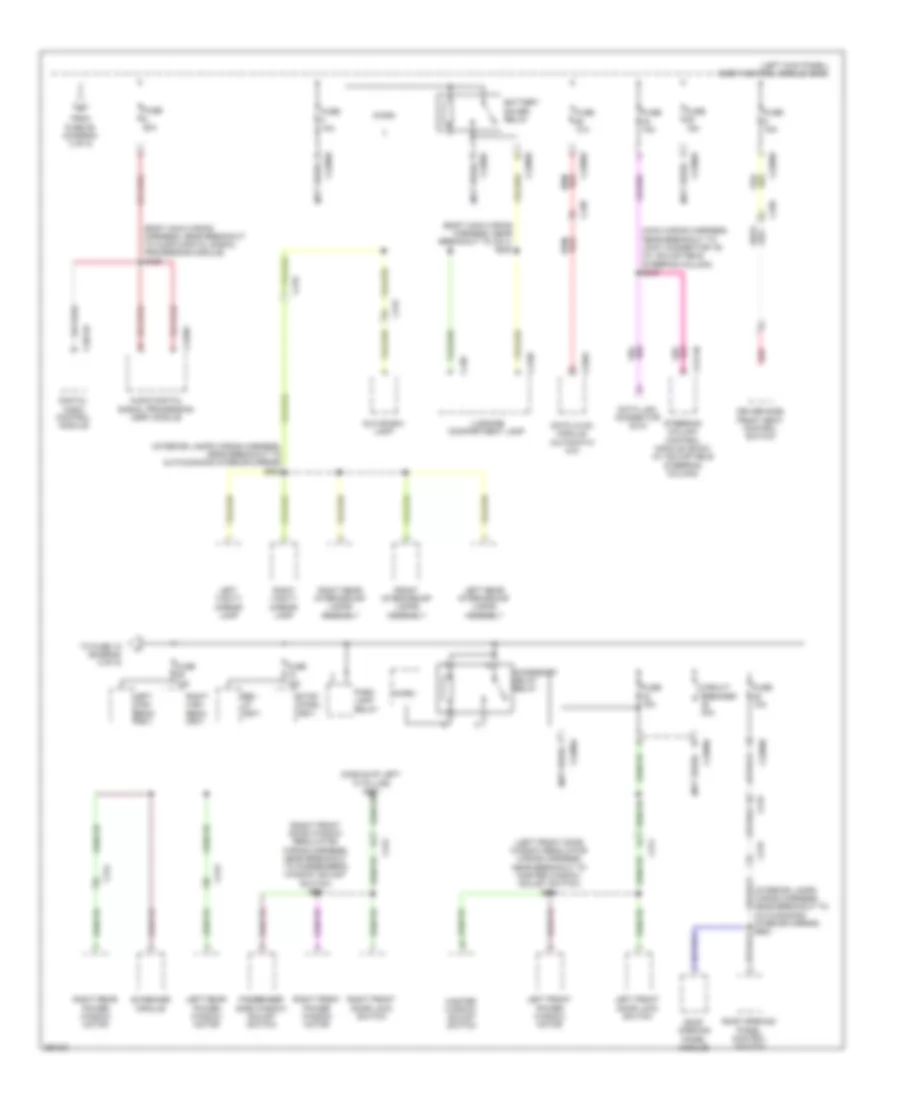
Электросхема блока предохранителей и реле (4 из 5) для Lincoln MKS 2013
Электросхема блока предохранителей и реле (4 из 5) для Lincoln MKS 2013 - Список элементов:
- (body main wiring harness, near breakout to audio digital signal processing module) s409
- (body main wiring harness, near breakout to c211) s220
- (interior lamps wiring harness, near breakout to auto-dimming interior mirror) s902
- (left front door window regulator wiring harness, near breakout to master window adjust switch) s504
- (left kick panel) body control module (bcm)
- (main wiring harness, near breakout to joint connector 16) (w/ adjustable steering column) s243
- (not used)
- (right front door window regulator wiring harness, near breakout to passenger's window adjust switch) s601
- Accessory delay relay
- Audio digital signal processing (dsp) module
- Battery saver relay
- C215
- C219
- C2280a
- C2280b
- C2280d
- C2280f
- C228a
- C238
- C2414b
- C311
- C312
- C313
- C314
- C339
- C3521b
- C4198
- C428
- C4326c
- Circuit breaker 30a
- Data link connector (dlc)
- Datc hvac module (automatic a/c)
- Digital audio control module
- Driver side front seat control switch
- From fuse 26 (diagram 3 of 5)
- Front interior/map lamps assembly
- Fuse 10a
- Fuse 15a
- Fuse 20a
- Glove box lamp
- Left front door lock switch
- Left front power window motor
- Left high beam (fet)
- Left rear interior/map lamps assembly
- Left rear power window motor
- Left vanity mirror lamp
- Luggage compartment lamp
- Master window adjust switch
- Micro
- Park lamp relay
- Passenger side window adjust switch
- Red
- Rev lp (fet)
- Right front door lock switch
- Right front power window motor
- Right high beam (fet)
- Right rear interior/map lamps assembly
- Right rear power window motor
- Right vanity mirror lamp
- Roof opening panel control switch
- Roof opening panel module
- Steering column control module (sccm) (w/ adjustable steering column)
- Stop/ chmsl (fet)
- Sunshade module
- To fuse 18 (diagram 5 of 5)
Электросхема блока предохранителей и реле (5 из 5) для Lincoln MKS 2013
Электросхема блока предохранителей и реле (5 из 5) для Lincoln MKS 2013 - Список элементов:
- (body main wiring harness, near breakout to audio digital signal processing module or c4208b) s411
- (body main wiring harness, near breakout to g302) s324
- (body main wiring harness, near breakout to g302) s363
- (dash panel to headlamp junction wiring harness, near breakout to battery junction box) s138
- (left kick panel) body control module (bcm)
- (main wiring harness, near breakout to passenger's temperature blend door actuator) (w/ head up display) s236
- (not used)
- 2nd row seat (fet)
- Audio digital signal processing (dsp) module
- Auto- dimming interior mirror
- Back- lighting led (fet)
- Battery junction box (bjb) (left side of engine compt)
- Bsi (fet)
- C211
- C215
- C219
- C2280b
- C2280d
- C2280e
- C2280f
- C2406
- C248
- C260
- C3047
- C3050
- C310a
- C3304b
- C3381
- C3382
- C3385a
- C3386a
- C340
- C4226a
- C4326c
- C4396b
- C466a
- C919
- Driver seat lumbar control module
- Fog lamp relay
- From battery junction box (bjb) (diagram 2 of 5)
- From fuse 39 j (diagram 4 of 5)
- From start/stop h (led) (fet) (diagram 3 of 5)
- Fuse 10a
- Fuse 15a
- Fuse 20a
- Fuse 5a
- Fuse 7.5a
- Head up display (hud) module (if equipped)
- Heated steering wheel module (hswm)
- Horn relay
- In-vehicle temperature/ humidity sensor
- Interior lighting (fet)
- Keypad illum (fet)
- Left corner lamp (fet)
- Left low beam (fet)
- Left side obstacle detection control module (sod-l) (if equipped)
- Lf turn lamp (fet)
- Lr stop/ turn lamp (fet)
- Lr turn lamp (fet)
- Micro
- Occupant classification system module (ocsm)
- Parking aid module (pam)
- Passenger seat lumbar control module
- Pcm wake up (fet)
- Premium audio
- Puddle lamp (fet)
- Rain sensor module
- Rear heated seat module
- Restraints control module (rcm)
- Rf turn lamp (fet)
- Right corner lamp (fet)
- Right low beam (fet)
- Right side obstacle detection control module (sod-r) (if equipped)
- Rr stop/ turn lamp (fet)
- Rr turn lamp (fet)
- Run/acc relay
- Subwoofer amplifier
- Thx audio
- Vehicle dynamics module (vdm)
- Video camera (w/ side obstacle detection)
- White light (fet)
- Wiper relay

 Čeština
 Dansk
Dansk Deutsch
 Ελληνικά
 English
 English
 Español
 Suomi
Suomi Français
 Français
 עברית
עברית Hrvatski
 Magyar
 Italiano
 日本語
日本語 한국어
한국어 Nederlands
 Português
 Português
 Română
 Русский
 Slovenčina
 Slovenščina
 Svenska
 Türkçe
 中文 (中国)