BODY COMPUTER
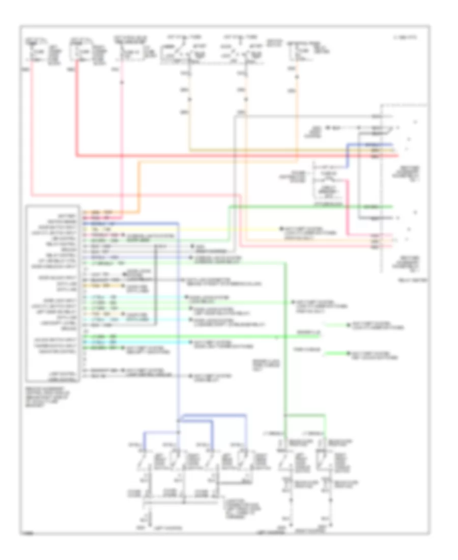
Body Computer Wiring Diagrams for Pontiac Bonneville SE 1995
List of elements for Body Computer Wiring Diagrams for Pontiac Bonneville SE 1995:
- (buick,olds) (pontiac)
- (c-car) (h-car)
- (left kickpad)
- (pontiac only)
- (right kickpad)
- 1995 vftc c
- A d
- Accy
- Anti-theft system (door lock tamper switches)
- Anti-theft system (horn relay)
- Anti-theft system (key unlock switches)
- Anti-theft system (lamp control module)
- Anti-theft system (lock cylinder switches)
- Anti-theft system (security indicators)
- B c
- Battery
- Bonneville
- Bonneville & park avenue only
- Bulb test
- C b
- Circuit breaker 1 30a
- Computer data lines
- Data line
- Data link connector (behind i/p right of steering column)
- Door handle sw input
- Door lock input
- Door locks system (left door isolation relay)
- Door locks system (lock relay)
- Door locks system (luggage compt lid release relay)
- Door switch input
- Door unlock input
- Fuse 15a
- Fuse 1d 15a
- Fuse 60a
- Fuse 8d 10a
- G e
- G200
- G203
- G203 (right kickpad)
- Ground
- Horn control
- Hot at all times
- Hot in run, bulb test and start
- I/p fuse block
- Ignition sense
- Ignition switch
- Indicator control
- Int lps relay ctrl
- Interior lights system (door leds)
- Interior lights system (interior lamps relay)
- J f
- Junction connector c340 (left front door sill, taped to harness)
- Lamp control
- Led control
- Left door iso relay
- Left front door handle switch
- Left front door switch
- Left rear door switch
- Left under- hood fuse block
- Ligg compt lid rel
- Lock
- Lock cyl switch input
- Nca
- Off
- Park avenue
- Pnk
- Power distribution system
- Reatined accessory power relay no. 1
- Red
- Relay center
- Relay control
- Remote accessory control (rac) module (behind right side of i/p, on multi-use bracket)
- Right front door handle switch
- Right front door switch
- Right rear door switch
- Right under- hood fuse block
- Run
- Start
- Tamper switch input
- Tan
- Unlock switch input
 Čeština
 Dansk
Dansk Deutsch
 Ελληνικά
 English
 English
 Español
 Suomi
Suomi Français
 Français
 עברית
עברית Hrvatski
 Magyar
 Italiano
 日本語
日本語 한국어
한국어 Nederlands
 Português
 Português
 Română
 Русский
 Slovenčina
 Slovenščina
 Svenska
 Türkçe
 中文 (中国)
 Polski